1
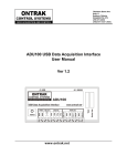
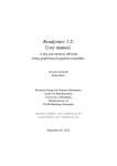
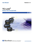
ADU71 USB to Current Output ( 4-20mA, 0-20mA Transmitter ) User Manual Ver 1.0 www.ontrak.net EU Declaration of Conformity We, the undersigned, Manufacturer: Ontrak Control Systems Inc. Address, City 764 Notre Dame Avenue, Unit 1, Sudbury Province, Country, Postal Code Ontario CANADA P3A2T2 Phone and FAX (705) 671-2652 (705) 671-6127 ( FAX) Email Address [email protected] certify and declare under our sole responsibility that the following Apparatus: Model No: ADU71 SN: H10000 and higher. Description: USB to Current Output Interface Brand: Ontrak Control Systems Inc. Conforms with the essential requirements of the EMC Directive 2004/108/EC, via Annex II, based on the following specifications applied: RF Emissions EN55011:2009/A1:2010 Class B ESD Immunity IEC 61000-4-2:2008 Level 2 Criterion B RF Immunity IEC 61000-4-3:2006 +A1:2007 +A2:2010 Level 2 Criterion B And therefore complies with the essential requirements and provisions of the EMC directive. The technical documentation is kept at the following address: Company: Address, City Country, Postal Code Phone Number Fax, Email Ontrak Control Systems Inc. 764 Notre Dame Ave, Unit 1, Sudbury Canada P3A 2T2 (705) 671-2652 (705) 671-6127 [email protected] Name of Person binding the manufacturer. Tom Fortin- Director Ontrak Control Systems Inc Page2of18ADU71 User Manual Oct 29, 2013 Sudbury , Ontario, CANADA Table Of Contents 1. What is Included and Where to Start 4 2. ADU71 Features 4 3. The ADU71 STATUS LED 5 4. AduHidTest USB Device Test Program 6 5. ADU71 Command Summary 10 6. ADU71 Command Descriptions 11 6a) Setting Range and Output Current 6b) Reading Output Current 6c) Setting the Slew Rate 6d) Using the Watchdog Feature 6e) Using the Status Feature 6f ) The ADU71 Reset Command 7. The ADU71 Connection Diagrams 7a) Connecting to Current Input Devices 7b) Connecting to Voltage Input Devices 8. Specifications and Dimensions 11 11 12 12 13 13 14 14 15 17 Page3of18ADU71 User Manual 1. What is Included and Where to Start The ADU71 ships complete with a 10' USB cable, and this User Manual. A complete SDK including DLL, programming language examples, and AduHidtest software is available at: http://www.ontrak.net/programming.htm First time users should first review the ASCII command set for the ADU71 and then use AduHidTest USB test software to become familiar with the operation of the various features of the product. Note: The AduHid DLL requires one of the following Windows operating systems. 98SE, 2000, XP, Vista, Windows 7, Windows 8. The programming section of the web site also contains examples for use with various other operating systems and provides details that allow use of the ADU71 without using the Windows based AduHid DLL 2. ADU71 Features •Provides a standard powered current loop output of 4-20mA or 0-20mA. •Drives 4-20mA, 0-20mA devices or 1-5VDC, 0-5VDC or 0-10VDC inputs using external resistors. •Ideal for controlling variable frequency drives ( VFD ), valves etc. •Internal isolated 24VDC supply derived from USB bus. No need for external loop power supply. •Programmable slew rate from 1ms to 10 seconds. •Programmable host watchdog function. •Loop error detection. •Over temperature detection •2500V Isolation to loop. •Bus Powered •High retention USB Connector •CE Marked •Bi-colour LED status indicator. •High quality cage-clamp type terminal blocks. •Uses standard HID drivers included with Windows 98SE, 2000, XP, 7, 8 32-bit or 64-bit •Mini-driver ( DLL ) provided for use with VB,VC, .NET, LabVIEW and TestPoint and others. •Meets IEC61000-4-2 ESD protection for USB port. •Available in flange ( standard ) or DIN rail mount. Page4of18ADU71 User Manual 3. The ADU71 STATUS LED The ADU71 STATUS LED is a bi-colour ( Red/Green) led indicator used to identify the current status of the ADU71 USB connection. The LED modes are; RED -ADU71 powered but not enumerated. GREEN -ADU71 powered and enumerated by host computer. OFF -ADU71 disconnected from USB bus OR host computer has entered SLEEP mode. The ADU71 can be connected to the USB bus via the enclosed 10' A-B USB cable. The cable provides both power and communications connections to the ADU71. When first connected, the STATUS led will turn RED indicating power is applied. For Windows operating systems, a message may flash on the screen indicating; “New hardware Found” ADU71 USB to Current Output Interface Depending on the version of Windows, the host may prompt to search for a driver. Select, Let Windows Search for a Driver and click next. After a few seconds, the STATUS led will turn green indicating enumeration is complete. The enumeration process is completely transparent to the application program as the ADU71 is a USB HID class device. Enumeration is completed by the Windows ( or other ) operating system standard USB HID drivers. The ADU71 can be connected directly to the host hub or externally powered hubs. Caution: ( Use of System Sleep ): If the Windows ( or other ) operating system allows the host computer to enter sleep mode, attached USB devices will be set to suspend mode. In this mode the power draw of the ADU71 drops to less than 2.5mA ( USB2.0 Specification ) and the current loop output is put into high impedance mode. In suspend mode the ADU71 Status LED is turned off. Once the host computer is revived from sleep mode, the ADU71 status LED will turn to green and the output will have to be re-enabled by the host application. Ensure system power settings are set such that the host computer does not enter sleep mode during normal operation. Page5of18ADU71 User Manual 4. AduHidTest USB Device Test Program AduHidTest is a Windows based USB device test program used to test the connection of ADU data acquisition devices to a USB port. The program is also a useful tool to allow programmers to become familiar with the ADU71 command set. AduHidTest software can be downloaded from the Ontrak website at: http://www.ontrak.net/programming.htm . Note that the program requires the AduHid.dll to operate and it should be copied to the dame directory as the AduHidTest.exe file. Getting Started: There are three steps in using a USB device in any application software. The three steps are; 1. Obtain a handle for the USB device. 2. Send commands to the USB device. 3. Receive data from the USB device. STEP 1: Obtain a handle for the ADU71 A handle is a unique code that application software uses to identify a USB device for the purpose of reading and writing to the device. A USB bus can have up to 128 devices connected to a single host and there are three criteria that can be used to open a handle. The three criteria are, Vendor ID, Product ID and Serial Number. If a single device is connected to the bus, any of the three criteria may be used. If multiple devices are connected, we recommend using the Serial Number to open the handle. ( All ADU devices have their unique serial number printed on the top label ) When run, the AduHidtest Software will display the following window. Figure 1: AduHidTest Software Window Page6of18ADU71 User Manual The Open/Close section of the window is where the handle is determined. Click on the Show List button to view the devices connected to the USB bus. ( Note: Only ADU devices will be listed ) Figure 2 is the window that appears when the Show List Button is clicked. Figure 2: ShowList Window The window indicates that there is one ADU71 connected with serial number T10002. Select the device by double clicking on the text “ ADU71 serial number = T10002”. The AduHidTest main window will now display the product ID and Serial number. Click the By Serial # radio button and then click Open to open the handle to the selected ADU71. Figure 3: Handle Open to ADU71 Page7of18ADU71 User Manual STEP 2: Sending Commands to the ADU71 Once connected, you may now send commands to the available "pipes" on the ADU71 device. Pipes are the individual connections to functional sections of the ADU71 . The Device Pipe is used to send standard ASCII ADU commands to control the peripherals built into the ADU71 such as the current loop output or the watchdog timer. The ADU71 does not use the RS232 or Stream pipes. Type "wr65535" ( Enable loop in 0-20mA mode and set current to 20mA) into the device pipe send window and click Send ADU . An OK will appear beside the Send ADU button if successful and the ADU71 will begin sourcing 20mA at its Loop output terminals. Note that ADU commands are not case sensitive. Figure 4: Sending "wr65535" Command Page8of18ADU71 User Manual STEP 3: Receiving Data from the ADU71 Some commands will cause a response to be sent from the ADU71 back to the host computer. For example, if an "rd" ( read output current setting ) command is sent, the ADU71 will send back the 5 digit value of the present output current setting. To read responsive commands, simply click the Receive ADU button and the data will be displayed. Figure 5: Sending "rd" Command Figure 6: Receiving Data These procedures can be repeated using the various commands available on the ADU71. The AduHidTest software is an invaluable tool to allow programmers to become familiar with any ADU product. Page9of18ADU71 User Manual 5. ADU71 Command Summary WRnnnnn Sets output current to nnnnn and sets range to 0-20mA ( nnnnn = 00000 to 65535 ) WLnnnnn Sets output current to nnnnn and sets range to 4-20mA ( nnnnn = 00000 to 65535 ) RD Returns present current output setting. SRn Sets slew rate to desired rate. ( n = 0 to 7 ) 0 1ms 1 10ms ( Default or power-up setting ) 2 50ms 3 100ms 4 500ms 5 1s 6 5s 7 10s WDn Sets watchdog. ( n = 0 to 4 ) 0 OFF ( Default or power-up setting ) 1 100ms 2 1s 3 5s 4 10s STA Returns present status. 0 Loop Output Disabled 1 Loop Enabled 2 Slew Active 3 Loop is OPEN 4 Over Temperature RST ( Default or power-up setting ) ( No fault ) ( The output is presently slewing ) ( Fault condition ) (ADU71 core above 150C ) Resets ADU71 to power-on ( default ) condition. Page10of18ADU71 User Manual 6. ADU71 Command Descriptions 6a) Setting Range and Output Current The ADU71 operates in either a 4-20mA or a 0-20mA range. The range is set by the commands used to set the desired output current. The current is set using a 16-bit integer number ranging from 00000 ( 0%FS) to 65535 ( 100% FS ) The commands to set the output current and range are: WRnnnnn WLnnnnn Sets output current to nnnnn and sets range to 0-20mA ( nnnnn = 00000 to 65535 ) Sets output current to nnnnn and sets range to 4-20mA ( nnnnn = 00000 to 65535 ) Examples; WR32768 WR65535 WL32768 WL00000 Sets range to 0-20mA and sets current to 32768/65535 X 20 = 10mA Sets range to 0-20mA and sets current to 65535/65535 X 20 = 20mA Sets range to 4-20mA and sets current to 32768/65535 X 16 + 4 = 12mA Sets range to 4-20mA and sets current to 00000/65535 X 16 + 4 = 4mA 6b) Reading Output Current The ADU71 output current setting can be read back as a 16-bit number from 00000 ( 0% FS ) to 65535 ( 100% FS ). The 16 bit integer number returned represents the current setting and the output current can be calculated depending on which command was used to set the current. If the 0-20mA range ( WRnnnnn ) was used to set the output current the output current setting can be calculated using the following formula; nnnnn/65535 X 20 = Output Current Setting If the 4-20mA range ( WLnnnnn ) was used to set the output current the output current setting can be calculated using the following formula; nnnnn/65535 X 16 + 4 = Output Current Setting The command to read back the present current setting is; RD Returns present current output setting. For example; RD returns... 32768 If output current was set with the WRnnnnn command , output current setting is 32768/65535 X 20 = 10mA If output current was set with the WLnnnnn command , output current setting is 32768/65535 X 16 + 4 = 12mA RD returns... 12657 If output current was set with the WRnnnnn command , output current setting is 12657/65535 X 20 = 3.86mA If output current was set with the WLnnnnn command , output current setting is 12657/65535 X 16 + 4 = 7.09mA Page11of18ADU71 User Manual 6c) Setting the Slew Rate The ADU71 slew rate can be set to eight different rates ranging from 1ms to 10 seconds. The slew rate is the rate at which the output changes and the specified rate is the time it takes for the output to change from 0% FS to 100% FS. The slew rate settings are: 0 1 2 3 4 5 6 7 - 1ms 10ms 50ms 100ms 500ms 1s 5s 10s ( Default or power-up setting ) To set the slew rate the following command is used; SRn Sets slew rate to desired rate. ( n = 0 to 7 ) Example; SR3 Sets slew rate to 100ms The slew rate can be read back using the following command; SR Returns present slew rate setting Example; SR returns... 5 Slew rate is set to 5 seconds. 6d) Using the Watchdog Feature The ADU71 features a host watchdog function that is used to disable the output current if the host application becomes inactive for a specified time period. When enabled, the watchdog timer will be reset with every write to the ADU71 by the host software. 0 1 2 3 4 - OFF 100ms 1s 5s 10s ( Default or power-up setting ) To set the watchdog operation the following command is used; WDn Sets watchdog. ( n = 0 to 4 ) Example; WD3 Sets watchdog time to 5 seconds Page12of18ADU71 User Manual The watchdog setting can be read back using the following command; WD Returns present watchdog setting Example; WD returns... 0 Watchdog setting is 0. ( OFF ) IMPORTANT: 1.) When the watchdog times out, the ADU71 output current will go to zero and the output will switch to high impedance mode. To re-enable the output after a watchdog timeout occurs use either the WRnnnnn or WLnnnnn command. 2.) If the host computer goes to sleep and suspends the USB connection, the ADU71 will turn off the output immediately regardless of watchdog timer settings. 6e) Using the Status Feature The ADU71 features a status function that returns a numeric indication of the ADU71 operating status. The five operating status conditions are: 0 1 2 3 4 - Loop Output Disabled Loop Enabled Slew Active Loop is OPEN Over Temperature ( Default or power-up setting ) ( No fault ) (Output is presently slewing ) ( Fault condition ) ( Fault condition, ADU71 core above 150C ) The operating status can be read back using the following command; STA Returns present status. Example; STA returns... 1 Loop is enabled and no fault is detected. 6f) The ADU71 Reset Command The ADU71 features a reset command than can be used to return the ADU71 to the power-on state at any time. The reset command is ; RST IMPORTANT NOTE : ADU71 Test Software and V2.0 DLL The ADU71 is a Full Speed USB product and requires the use of the new AduHidTestV2.0 and the Aduhid.dll Ver 2.0 or higher. The V2.0 DLL and AduHidTest V2.0 Software can be downloaded at http://www.ontrak.net/programming.htm Page13of18ADU71 User Manual 7. ADU71 Connection Diagrams The ADU71 USB to Current Output Interface is a USB bus powered current loop source for driving 4-20mA or 0-20mA input devices. The ADU71 can also be used with external resistors to provide 1-5VDC, 0-5VDC or 0-10VDC signals for variable frequency drives, valves etc. The ADU71 internally generated 24VDC loop supply eliminates the need for an external loop power supply. 7a) Connecting to 4-20mA Current Input Devices. The first connection example shows the correct method to connect a device which has a 4-20mA current loop input. Figure 1 shows the correct connections. Note that the "+" of the LOOP output is connected to the "+" of the device under control and, the "-" of the LOOP output is connected to the "-" of the device under control as shown in Figure 1. Figure1: ADU71 connection to a 4-20mA current loop input device such as a variable frequency drive ( VFD ) motor controller. If the application requires two current input devices they can be connected in series as shown in Figure 2. Figure 2: ADU71 connections to multiple 4-20mA current loop input devices. Page14of18ADU71 User Manual 7b) Connecting to Voltage Input Devices. Voltage input devices can also be connected to the ADU71 LOOP output provided the input connections are terminated with an appropriate resistor. For 1-5VDC input devices the input should be shunted with a 250 ohm resistor to convert the 4-20mA current signal to a 1-5VDC signal as shown in Figure 3. CAUTION: Ensure the resistor is correctly and firmly connected to the device input terminals. If the resistor is not correctly connected, or open circuit, the ADU71 will apply 24VDC to the input of the device under control when the ADU71 loop current is enabled. This may damage the input circuitry of the device under control. Figure 3 : ADU71 driving a 1-5VDC input VFD or valve. If the device under control has a 0-5VDC input, the connections are identical to Figure 3, however, the ADU71 LOOP is programmed to provide 0-20mA to the loop as shown in Figure 4. Figure 4 : ADU71 driving a 0-5VDC input VFD or valve. Page15of18ADU71 User Manual If the device under control has a 0-10VDC input, a 500 ohm resistor ( or two 250 ohm resistors in series) should be shunted across the input terminals of the device under control. The ADU71 LOOP is then programmed to provide 0-20mA to the loop as shown in Figure 5. CAUTION: Ensure the resistor is correctly and firmly connected to the device input terminals. If the resistor is not correctly connected, or open circuit, the ADU71 will apply 24VDC to the input of the device under control when the ADU71 loop current is enabled. This may damage the input circuitry of the device under control. Figure 5 : ADU71 driving a 0-10VDC input VFD or valve. Multiple voltage input devices can also be connected to the ADU71 LOOP output provided each is shunted by the appropriate resistor as shown in Figure 6. Figure 6 : ADU71 driving multiple 0-5VDC voltage input devices with 0-20mA output. Page16of18ADU71 User Manual 8. Specifications and Dimensions Supply Voltage NONE ( Bus Powered ) USB Supply Current ( Loop Disabled ) 65mA Typical 75mA Max USB Supply Current ( 20mA Loop Current ) 180mA Typical 200mA Max Operating Temperature -25C Min to 85C Max Current Loop Output Resolution 16 Bits Range 4-20mA or 0-20mA, programmable Total Unadjusted Error -0.3%FSR MIN +0.3%FSR MAX Full Scale Error -0.2%FSR MIN +0.2% FSR MAX Temperature Stability +/- 16 ppm FSR/Degree C Slew rate 1ms to 10s Programmable Isolation 2500V Internal Loop Power Supply Voltage 24V Nominal Isolation 2500V Loop Compliance Voltage 21V Minimum Special Functions Internal Loop Power Supply Internal 24VDC supply eliminates need for external loop power supply. Mounting Options Flange Mount ( STANDARD ) , DIN Rail Page17of18ADU71 User Manual Notes: ________________________________________________________________ ________________________________________________________________ ________________________________________________________________ ________________________________________________________________ ________________________________________________________________ ________________________________________________________________ ________________________________________________________________ ________________________________________________________________ Page18of18ADU71 User Manual