1
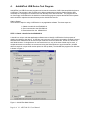
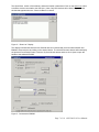
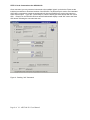
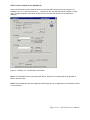
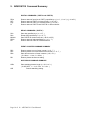
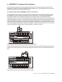
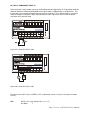
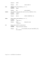
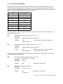
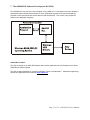
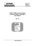
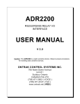
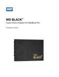
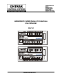
ADU208/218 USB Relay I/O Interface
User Manual
Ver1.2
www.ontrak.net
This ADU208/218 is warranted from defects in manufacturing for a period of 1 year and
liability is limited to the purchase price of the product
C2003 Ontrak Control Systems Inc.
Page 2 of 18 ADU208/218 User Manual
Table Of Contents
1.
W hat is Included and W here to Start
4
2.
ADU208/218 USB Relay I/O Features
4
3.
Connecting the ADU208/218 to a USB Bus
5
4.
AduHidTest USB Device Test Program
6
5.
ADU208/218 Command Summary
10
6.
ADU208/218 Command Descriptions
11
6a) Digital Input Port Commands
6b) Relay Output Commands
6c) Event Counter Commands
6d) W atchdog Commands
11
13
15
16
7.
The ADU208/218 Software Development Kit ( SDK )
17
8.
Electrical Specifications
18
Page 3 of 18 ADU208/218 User Manual
1.
What is Included and Where to Start
The ADU208/218 ships complete with a 10' USB cable, this User Manual and a 3.5" diskette titled ADUSDK.
The ADU-SDK diskette inlcudes the following files;
AduHid.dll
AduHidTest.exe
AduHidHelp.chm
VisualC-EG
VisualBasic-EG
BorlandC-EG
Various support files
DLL to allow applications to communicate with the ADU208/218 on the USB
bus.
Software application used to test ADU products and allow programmers to
become familiar with the ADU ASCII commands.
Software development kit ( SDK ) in CHM ( Windows Help File ) format.
( folder)
Visual C program examples from SDK
( folder)
Visual Basic program examples from SDK
( folder)
Borland C program examples from SDK
First time users should first review the ASCII command set for the ADU208/218 and then use
AduHidTest to become familiar with the operation of the various features of the product.
Note: The AduHid DLL requires one of the following Windows operating systems. 98SE, 2000 or XP
Application programs should be written using the Software Design Kit ( SDK ) located on the ADU-SDK
diskette. The SDK contains explanations of how the various communication pipes can be accessed using
the AduHid DLL. Example code is given for Visual Basic, Visual C and Borland C. The SDK help file is
designed to be run on the development PC when programming. This allows programmers to cut-andpaste specific functions directly into an application. Additional examples and applications are posted on
our web site at www.ontrak.net
2.
ADU208 / 218 USB Relay I/O Interface Features
-Provides a standard PC with PLC ( programmable logic controller ) functions.
-Low-cost .
-Bus Powered, No external power supply required.
-8, N. O. relay contact outputs rated 5.0A @ 120VAC, 5.0A @ 30VDC ( ADU208 )
-8, Solid-State PhotoMOS Relay outputs rated 1.0A @ 120VAC, 1.0A @ 120VDC ( ADU218 )
-8 Digital inputs suitable for contact or TTL Input , also accept up to 28VDC .
-Inputs feature optical isolation to 3500V ( 500V channel to channel ).
-Programmable watchdog functions.
-Bi-colour LED status indicator.
-Self-resetting, fused 5V output.
-High quality cage-clamp type terminal blocks.
-Uses standard HID drivers included with Windows 98SE,2000,XP.
-Mini-driver ( DLL ) provided for use with VB,VC, LabVIEW and TestPoint.
-Programming examples and sample code included for VB, Visual C++ .
-Eight, 16-bit event counters.
-Programmable debounce setting for event counters.
-Meets IEC61000-4-2 ESD protection for USB port.
-Available in enclosure or as PCB only.
Page 4 of 18 ADU208/218 User Manual
3.
Connecting the ADU208 /218 to a USB Bus
The ADU208/218 can be connected to the USB bus via the enclosed 10' A-B USB cable. The cable
provides both power and communications connections to the ADU208/218. When first connected, the
STATUS led will turn RED indicating power is applied. A message will flash on the screen indicating;
“New hardware Found”
ADU208 USB Relay I/O Interface
Depending on the version of Windows , the host may prompt to search for a driver. Select,
Let Windows Search for a Driver
and click next.
After a few seconds, the STATUS led will turn green indicating enumeration is complete. The
enumeration process is completely transparent to the application program as it is completed by the
Windows operating system
The STATUS led will remain green unless a watchdog timeout ( See Watchdog Commands Section )
occurs.
The ADU208/218 can be connected directly to the host hub or either, external powered, or non-powered
hubs.
Caution: ( Use of System Standby ): If the Windows operating system puts the system into “ Suspend
” mode, all USB hubs are issued a Reset when the Suspend mode is exited. This will cause the
ADU208/218 to lose power briefly, resulting in the event counter data being lost and all relays to reset.
Open the power options section in the Windows control panel and ensure “System Standby” is set to
never.
Caution: ( Use of PWR Terminals ): The auxiliary power connections labelled VDD and GND are a nonisolated output and no external power supply should be connected to these terminals. The power output
is provided to allow use of dry contact inputs with the digital input lines. If the supply is to be used with
dry contact inputs, GND should be connected to COM A and/or COM B, and the dry contact
connections made between VDD and the selected digital input line. If this power output is used to power
external circuits, no more than 20mA should be drawn if all relays are to be energized at once. If no more
than 4 relays are to be energized at one time, up to 50mA can be drawn from the VDD supply.
Page 5 of 18 ADU208/218 User Manual
4.
AduHidTest USB Device Test Program
AduHidTest is a USB Device test program used to test the connection of ADU data acquisition devices to
a USB port. The program is also a useful tool to allow programmers to become familiar with the ADU
command set. The program is located in the root directory of the ADU-SDK disk. The program can be
run from floppy or transferred to the hard drive. Note that the program requires the AduHid.dll to operate
and it should be copied to the same directory as the AduHidTest.exe file.
Getting Started:
There are three steps in using a USB device in any application software. The three steps are ,
1. Obtain a handle for the ADU208/218.
2. Send commands to the ADU208/218.
3. Receive data from the ADU208/218.
STEP 1: Obtain a handle for the ADU208/218
A handle is a unique code that application software uses to identify a USB device for the purpose of
reading and writing to the device. A USB bus can have up to 128 devices connected to a single host and
there are three criteria that can be used to open a handle. The three criteria are, Vendor ID, Product ID
and Serial Number. If a single device is connected to the bus, any of the three criteria may be used. If
multiple devices are connected, we recommend using the Serial Number to open the handle ( All ADU
devices have their unique serial number printed on the top label ) The AduHidTest program main Window
is shown in Figure 1.
Figure 1: AduHidTest Main Window
Page 6 of 18 ADU208/218 User Manual
The Open/Close section of the window is where the handle is determined. Click on the Show List button
to view the devices connected to the USB bus. ( Note: Only ADU devices will be listed ) Figure 2 is the
window that appears when the Show List Button is clicked.
Figure 2: " Show List " Display
The display indicates that there are two ADU200 devices connected with serial numbers A00222 and
B00099. Select a device by clicking on the desired device. The AduHidTest main window will now display
the product ID and Serial number. Click the By Serial # radio button and then click Open to open the
handle to the selected ADU200.
Figure 3: Connected to B00099
Page 7 of 18 ADU208/218 User Manual
STEP 2: Send Commands to the ADU208/218
Once connected, you may now send commands to the available "pipes" on the device. Pipes are the
individual connections to functional sections of the ADU200. The Device Pipe is used to send standard
ASCII ADU commands to control the peripherals built into the ADU200 such as the relay outputs or
event counter inputs. Type "sk3" ( Close relay K3 ) into the device pipe send window and click Send
ADU . Relay K3 on the ADU200 will close and the software will display a small "OK" next to the Send
ADU button indicating the command was sent.
Figure 4: Sending "sk3" Command
Page 8 of 18 ADU208/218 User Manual
STEP 3: Receive Data from the ADU208/218
Some commands will cause a response to be sent from the ADU device to the host computer. For
example, if an "re1" ( read event counter 1 ) command is sent, the ADU200 will send back the 5 digit
count. To read responsive commands, simply click the Receive ADU button and the data will be
displayed.
Figure 5: Sending "re1" and Receiving Count Data
Note1: The ADU208/218 does not support the RS232 pipe and so no explanation of its operation is
listed in this document.
Note2: The ADU208/218 does not support the stream pipe and so no explanation of its operation is listed
in this document.
Page 9 of 18 ADU208/218 User Manual
5. ADU208/218 Command Summary
DIGITAL COMMANDS ( PORT A and PORT B )
RPyn
RPy
PAy
PI
Returns status of input line in PORT y specified by n ( n= 0 , 1, 2 or 3 ) ( y =A or B )
Returns status of PORT y in binary format. ( y =A or B )
Returns status of PORT y in decimal format. ( y =A or B )
Returns status of PORT A and PORT B in decimal format.
RELAY COMMANDS ( PORT K )
SKn
RKn
MKddd
RPKn
PK
Sets relay specified by n ( n = 0-7 )
Resets relay specified by n ( n= 0 - 7 )
Sets PORTK to decimal value dd ( dd= 0 to 255 )
Returns status of relay specified by n ( n= 0 - 7 )
Returns status of PORT K in decimal format.
EVENT COUNTER COMMAND SUMMARY
REx
RCx
DBn
DB
Returns present count of event counter ( x = 0 - 7 )
Returns present count and clears event counter ( x = 0 - 7 )
Sets de-bounce time of event counters ( n=0,1 or 2 )
( 0 =10ms, 1 = 1ms, 2 = 100us, )
Returns present de-dounce setting.
WATCHDOG COMMAND SUMMARY
WDn
WD
Sets watchdog timeout length (n = 0,1,2 or 3 )
( 0 =WD OFF , 1 = 1s, 2 =10s, 3 = 1min. )
Returns watchdog setting.
Page 10 of 18 ADU208/218 User Manual
6. ADU208/218 Command Descriptions
All commands are specified as non-terminated ASCII strings. The maximum length of command and
data strings is 7 bytes. Commands are passed via the AduHid DLL to the ADU208/218 as a seven byte
packet and unused bytes are sent as NULL ( 00h ).
6a) DIGITAL INPUT PORT COMMANDS ( PORT A and PORT B )
The ADU208/218 device contains two 4-bit input ports labelled PORT A and PORT B. Both input ports
are isolated from all other external connections, and from each other, using opto-isolators with better
than 3000V isolation. Each of the two input ports has a COM connection ( COM A and COM B )
associated with it for connection of input device common voltages. Input devices can be connected using
external DC voltages of up to 28V. The VDD output terminals provide a nominal 5VDC output that can be
used as a supply to connect dry contact inputs ( switches, pushbuttons etc) to the digital inputs. When
using the internal VDD supply to connect dry contact inputs, GND must be connected to COM A or COM
B ( or both ) to allow a return path for input current. Figure 6A shows how dry contacts can be connected
using the ADU208/218 internal supply. Note that GND is connected to COM A.
Figure 6A: Dry Contact Connections Using Internal VDD Supply.
Figure 6B demonstrates the connection of dry contact inputs using an external DC supply. Note that the
common of the external supply is connected to COM B, as the inputs used in this example are PB2 and
PB3.
Figure 6B: Dry Contact Connections Using External Supply.
Page 11 of 18 ADU208/218 User Manual
RPyn
Returns status of input line in PORT y specified by n ( n= 0 , 1, 2 or 3 ) ( y =A or B )
# of Bytes
4
Response
1 byte ( 0 or 1 )
Example;
RPy
;PA2 is High.
Returns status of PORT A in binary format. ( y =A or B )
# of Bytes
3
Response
4 bytes ( 0000 tp 1111 binary ) ( order is MSB-LSB )
Example;
Py
RPA2
1 ( response)
RPA
0100 ( response)
;PA2 is High, PA0,PA1 and PA3 are Low
Returns status of PORT y in decimal format. ( y =A or B )
# of Bytes
2
Response
2 bytes ( 00 to 15 in decimal )
Example;
PA
15 ( response)
;All lines are High..
The following command has been included to allow polling of both digital ports with a single command.
The response to the PI command is an 8 bit response represented in decimal format ( 000 to 255 ). The
LSB of the response is PA0 and the MSB is PB3.
PI
Returns status of PORT A and PORT B in decimal format.
# of Bytes
2
Response
3 bytes ( 000 to 255 in decimal )
Example1;
PI
128 ( response)
;PB3 is HIGH, all others are LOW
Example2;
PI
003 ( response)
;PA0 and PA1 are HIGH, all others are LOW
Page 12 of 18 ADU208/218 User Manual
6b) RELAY COMMANDS ( PORT K )
There are 8 type A relay contact outputs in the ADU208 rated at 5A@120VAC or 5A @ 30VDC while the
ADU218 features 8 Solid-State PhotoMOS relay outputs rated at 1A@120VAC or 1A @120VDC . The
functionality of the commands between the two products is identical. AC or DC load may be connected
using the outputs as switches to apply external power to loads. Figures 6C and 6D show the proper
connection of DC and AC loads.
Figure 6C: Connection of DC Loads
Figure 6D: Connection of AC Loads
The relays may be SET ( ON ) or RESET ( OFF ) individually or as an 8 bit port. The relay commands
include;
SKn
SETS ( ON ) relay specified by n ( n = 0-7 )
# of Bytes
3
Page 13 of 18 ADU208/218 User Manual
RKn
Response
NONE
Example;
SK2
RESETS ( OFF ) relay specified by n ( n= 0 - 7 )
# of Bytes
3
Response
NONE
Example;
MKddd
;opens contact K1
MK128
;SETS K7, RESETS K0 - K6.
Returns status of relay specified by n ( n= 0 - 7 )
# of Bytes
4
Response
1 byte ( 0 or 1 )
Example;
PK
RK1
Sets PORTK to decimal value ddd ( ddd= 0 to 255 ) ( K7-MSB, K0 = LSB )
# of Bytes
3 , 4 or 5
Response
NONE
Example;
RPKn
;closes contact K2
RPK2
1 ( response)
;Relay K2 is closed.
Returns status of PORT K in decimal format.
# of Bytes
2
Response
3 bytes ( 000 to 255 in decimal )
Example;
PK
;K0 -K3 are SET ( ON ), K4-K7 are RESET ( OFF ).
015 ( response)
Page 14 of 18 ADU208/218 User Manual
6c) EVENT COUNTER COMMANDS
Each digital input line on PORT A and PORT B has an event counter associated with it. The event
counters count low to high transitions and store them in a 16 bit counter that can be read or, read and
cleared. The event counters are numbered 0 to 7 and count from 00000 to 65535 followed by a rollover to
00000. The following table identifies the counter assignments;
C o unter
P O R T A ssignment
0
PA0
1
PA1
2
PA2
3
PA3
4
PB0
5
PB1
6
PB2
7
PB3
The event counters are read using either the RE command or the RC command if the counter is to be
clearing following the read.
REx
Returns present count of event counter ( x = 0 - 7 )
# of Bytes
3
Response
5 bytes ( 00000 to 65535 in decimal )
Example;
RCx
RE1
00023 ( response)
;PA1 has seen 23 Low to High Transitions
Returns present count and clears event counter ( x = 0 - 7 )
# of Bytes
3
Response
5 bytes ( 00000 to 65535 in decimal )
Example;
RC3
00156 ( response)
;PA3 has seen 156 Low to High Transitions
; ( Event Counter 3 is cleared )
The de-bounce time of the event counters can be set from 100us to 10ms ( DEFAULT = 1 ms ) using
the DB command as outlined below;
DBn
Sets de-bounce time of event counters ( n=0,1 or 2 )
( 0 =10ms, 1 = 1ms ( Default ) , 2 = 100us )
# of Bytes
3
Response
NONE
Example;
DB
DB0
;De-bounce is set to 10ms
Returns present de-bounce setting.
# of Bytes
2
Response
1 bytes ( 0,1, or 2 )
Example;
DB
0 ( response)
;De-bounce is set to 10ms
Page 15 of 18 ADU208/218 User Manual
6d) WATCHDOG COMMANDS
A programmable host watchdog is provided to allow predicted operation in the event the host PC stops
communicating with the ADU208/218. Upon timeout, all relays are RESET ( OFF ), WD =0, and the
status indicator will turn from GREEN to RED. Any command sent to either the ADU208/218 by the host
application, will reset the watchdog timer. For example, if the watchdog is enabled with a timeout of 10
seconds, the host must send at least one command every 10 seconds or a timeout will occur. To
determine if a watchdog timeout has occurred, read the timer setting. If the watchdog was set to 2, and
no command was sent for 10 seconds, a 0 will be returned indicating a timeout has occurred. Following a
timeout, the host must reload the timer setting as a timeout causes the setting to be cleared to 0 ( WD
OFF )
WDn
Sets watchdog timeout length (n = 0, 1, 2 or 3 )
( 0 =WD OFF ( DEFAULT ) , 1 = 1s, 2 =10s, 3 = 1min. )
# of Bytes
3
Response
NONE
Example;
WD
WD2
;Sets WD timeout to 10s
Returns watchdog setting.
# of Bytes
2
Response
1 bytes ( 0,1,2 or 3 )
Example;
WD
0 ( response)
Notes to Watchdog Operation:
;Watchdog not enables or timeout has occurred.
1. The watchdog is disabled upon power-up.
Page 16 of 18 ADU208/218 User Manual
7. The ADU208/218 Software Development Kit (SDK)
The ADU208/218 connects to the host computer using a USB Ver1.1 Low-Speed connection allowing a
guaranteed latency between data transfers of 10ms. Application programs must use the AduHid DLL
provided to send commands and receive data from the ADU208/218. This is done using simple API
calls from the application language.
AduHid DLL location
The SDK is located on the ADU-SDK diskette and includes explanations of how the pipes to the various
ADR208/218 features operate.
The SDK contains examples for use with Visual Basic, Visual C and Borland C. Additional programming
tutorials and applications are located at www.ontrak.net
Page 17 of 18 ADU208/218 User Manual
ADU208
ADU218
S upply C urrent ( A ll relays OFF )
12mA T yp. 15mA M A X
12mA T yp. 15mA M A X
S upply C urrent ( A ll R elays ON )
165mA T yp. 180mA M A X
85mA T yp. 95mA M A X
0-50C
0-50C
M echanical T YP E A
S o lid-S tate P ho to M O S
A C Ratings
5A @ 120 V A C
1A @ 120 V A C
D C R atings
5A @ 30 V D C
1A @ 120 D C
V in H IG H ( M A X )
28V D C
28V D C
V in H IG H ( M IN )
2V D C
2V D C
V in LO W ( M A X )
0.7V D C
0.7V D C
V in LO W ( M IN )
0V D C
0V D C
2700 O hm s
2700 O hm s
R eso lutio n
16 B its
16 B its
Input T ype
C o ntact, T T L, V o ltage up to 28VD C
C o ntact, T T L, V o ltage up to 28VD C
1K H Z
1 KHZ
2700 O hm s
2700 O hm s
10m s, 1m s, 100us o r N O N E
10m s, 1m s, 100us o r N O N E
D eskto p, Velcro , DIN R ail
D eskto p, Velcro , DIN R ail
O perating T emperature
R elay Outputs ( 8 )
T ype
D igital Inputs ( 8 )
Input Z ( MIN )
E v ent C ounters ( 8 )
M ax Frequency
Input Z
P ro gram m able D eB o unce
M o unting Optio ns
Page 18 of 18 ADU208/218 User Manual