1
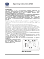
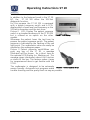
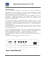
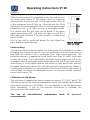
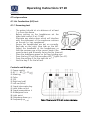
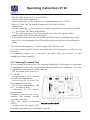
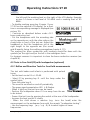
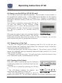
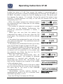
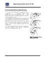
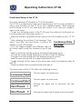
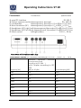
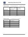
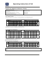
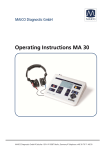
MAICO Diagnostic GmbH Operating Instructions MAICO ST 20 MAICO Diagnostic GmbH, Salzufer 13/14, D 10587 BERLIN, Tel. +49 30-70714650, Fax +49 30-70714699 Operating Instructions ST 20 Table of Contents Page 1 Introduction............................................................................................... 3 2 Description ................................................................................................ 4 3 Getting started .......................................................................................... 6 4.1 Air Conduction (AC) test ......................................................................... 8 4.1.1 Screening test .................................................................................. 8 4.1.2 Hearing Threshold Test ..................................................................... 9 4.1.3 Masking in the air conduction measurement ...................................10 4.2 Test of the Bone Conduction (BC) (ST 20 BC and ST 20 SISI only) ...........11 4.2.1 Hearing threshold test .....................................................................11 4.2.2 Masking in the bone conduction measurement (ST 20 BC and ST 20 SISI)..........................................................................................................11 4.3 Tests in Free field (FF) with loudspeaker (optional) ..................................12 4.3.1 Reflex and Direction Tests for free-field measurements ....................12 4.4 How to run the SISI-Test (ST 20 SISI only) ...............................................13 4.4.1 Preparation of the Test ....................................................................13 4.4.2 Training of the Patient .....................................................................13 5 Recommended literature ...........................................................................15 6 Care and maintenance of the instrument ..................................................16 7 Trouble shooting ......................................................................................17 8 Individual Setup of the ST 20 ....................................................................18 9 Technical Data and Accessory ...................................................................20 10 Warranty, Maintenance and After-Sales Service ......................................24 11 Safety Regulations ..................................................................................25 11.1 Electrical Safety: ...................................................................................25 Geba_ST20_Fe_10a.doc 1 851 307/1 04/10 Operating Instructions ST 20 11.2 Measuring security: ..............................................................................25 11.3 Device control:.....................................................................................25 11.4 Operation: ...........................................................................................25 11.5 Patient Safety: .....................................................................................25 Geba_ST20_Fe_10a.doc 2 851 307/1 04/10 Operating Instructions ST 20 1 Introduction Thank you very much for purchasing a quality product from the MAICO family. This ST 20 audiometer is manufactured to meet all quality and safety requirements, and has been certified with the CE-symbol according to Medical Directive 93/42/EEC. In designing the ST 20 we placed particular importance in making it a userfriendly device, meaning its operation is simple and easy to understand. And because ST 20 functions are software controlled, upgrading later to new, extended measurement functions will be simple and inexpensive. That means that you have invested in a device that will adjust to your future needs. This user manual should make it as easy as possible for you to become familiar with the functions of the ST 20. Please open out the flap of illustrations on the last page. The description of the position (e.g. ➄) of controls, displays and connections, found again in the text, will make it easier for you to learn how to operate the ST 20. If you have problems or have ideas for further improvements, please get in touch with us. Simply call. Your MAICO-team Geba_ST20_Fe_10a.doc 3 851 307/1 04/10 Operating Instructions ST 20 2 Description The audiometer ST 20 is a quick-testing screening audiometer for audiometric tone examination of babies, children and adults. It is a handy semi-automatic audiometer that is easy to operate, facilitates quick, uncomplicated detection of hearing defects. It has been designed for use in the office of the paediatrician and in general practice, in the public health services and in occupational medicine. As a result of modern microprocessor technology, the ST 20 is very comfortable to use and has a high operating reliability. A PC interface for data transfer to a connected computer is available (special interface cord required). The tests can be performed with a continuous or pulsed tone via headphones. Masking with the opposite headphone is possible if needed. In addition bone conduction measurement can be done with the ST 20 BC and ST 20 SISI. Free-field transmission is possible via the optional loudspeaker. Moreover, the ST 20 SISI offers the opportunity to conduct the SISI-test. The frequency and intensity level are set without any electronic static noises. The test tone is adjusted by means of a slider control for the level (in 5 dB steps) and the frequency adjustments are made by electronic push buttons. The particular value of frequency/level is indicated by a red light point in the audiogram field. In addition, the optional LCD-display (picture 2) shows level and frequency (standard accessory of ST 20 SISI). The ST 20 offers eight test frequencies from 250 Hz up to 8 kHz and a range of -10 dBHL up to 100 dBHL for air conduction. Picture 1 Front panel of ST 20The bone conduction measurement with the ST 20 BC can be carried out with seven test frequencies from 250 Hz to 6 kHz and a range of -10 dBHL up to 70 dBHL. If requested, the test signal can automatic be masked with the opposite headphone. The optional loudspeaker delivers test levels from -10dBHL to 90 dBHL for free field measurement at a distance of 10 cm. Picture 1 Front panel of ST 20 Geba_ST20_Fe_10a.doc 4 851 307/1 04/10 Operating Instructions ST 20 In addition to the features found in the ST 20 BC, the ST 20 SISI offers the SISI-Test diagnostic function. For this purpose the ST 20 SISI is equipped with a patient response switch and a LCDdisplay which shows level and frequency or the SISI test information and the test score. Picture 2 LCD- Display The patient response switch is a standard accessory of the ST 20 SISI but is offered as an option on the other Picture 2 LCD-Display models. Whenever the patient hears the test tone he presses the patient response switch. The patient response is indicated by the flashing of the red light point. The audiometric value can easily be marked on the audiogram paper. Picture 3 Patient response switchWhen you push any key of the ST 20, a message (Flashtext) will be shown for a short time on the optional LCD-Display (i.e. Masking on). This message gives information about the function or status of the key. This feature makes it easy for inexperienced users to get familiar with the ST 20. The audiometer is designed to be extremely service friendly. Automatic test programs make Picture 3 Patient response switch trouble shooting and the yearly check as easy as possible. Geba_ST20_Fe_10a.doc 5 851 307/1 04/10 Operating Instructions ST 20 3 Getting started The ST 20 should be operated in a quiet room, so that the audiometric examinations are not influenced by outside noises. However, the sound insulation muffs of the headphones perform so well at excluding sound the instrument can be used in noisier environments. Electro-medical instruments, which emit strong electromagnetic fields (e.g. microwaves - radiotherapy devices), can influence the function of the audiometer. Therefore the use of these instruments is not allowed in close proximity to the audiometer. The test room must be at normal temperature, usually 15° C to 35° C, and the instrument should be switched on about 10 minutes before the first measurement to guarantee precise measuring results. If the device has been cooled down (e.g. during transport), please wait until it has warmed up to room temperature. Insert the instrument plug of the mains cord into the mains socket on the rear of the instrument ±. Insert the other end of the mains cord into a 230 V~shock-proof socket. Connect the right (red) headphone to the correspondingly labelled socket ¯ and the left (Blue) headphone to socket ° at the rear of the device. If your device is equipped with a patient response switch, plug it to socket ¬♦. The LCD-display is connected to socket «♣ and screwed into the ST 20. The bone conduction receiver of ST 20 BC and ST 20 SISI is connected to socket ®♠. The optional loudspeaker is connected to socket ♥. Picture 4 rear panel of ST 20 with connectors Geba_ST20_Fe_10a.doc 6 851 307/1 04/10 Operating Instructions ST 20 Slide the level control Ë completely to the top and turn on the device with switch Ã. The device starts its initial test automatically. During this test, all the light points (LED́s) Î in the audiogram form Í light up. After the test the 1 kHz light point Î in the audiogram form Í and the green signal presentation LED ♪ Ì light up (only in interrupter mode). It in dicates that the test tone can be heard. If the green signal presentation LED ♪ Ì does not light up and the 1 kHz light point Î flashes, the level control Ë needs to be set at -10 dB. Due to the built-in protective device the test signal has been faded out automatically. Picture 5 mains switch, slider level control Patient safety: The built-in protective device makes sure that during the initialization or when changing the channel as well as from air conduction to bone conduction or free field the patient’s ear is protected from high sound exposure. The protective device is triggered by sound levels more than 50 dBHL, and fades out the test sound. This is indicated by the flashing of the light points Î in the audiogram form Í and green signal presentation LED♪ Ì In this case, set the level control Ë to the upper position and when the light point stops flashing, the green signal presentation LED Ì lights up and the test sound is faded in. If during the initialization of the device the 250 Hz and 500 Hz light points Î start to flash, the device has detected an error. In this case, contact customer service (see chapter 10). Calibration of the device: The instrument, headphones, bone conduction receiver (ST 20 BC and ST 20 SISI only) as well as the optional loudspeaker match one another and have the same serial number (e.g. 6631520). It is not allowed to use the device with other transducers. If one of the acoustic transducers is replaced, the instrument must be recalibrated. The use of non-calibrated measurements! Geba_ST20_Fe_10a.doc audiometers 7 leads to incorrect 851 307/1 04/10 Operating Instructions ST 20 4 Test procedure 4.1 Air Conduction (AC) test 4.1.1 Screening test - - The patient should sit at a distance of at least 1 m from the device. Before putting on the headphones set the slider level control Ë at -10 dB. Eliminate any obstructions which will interfere with the placement of the earphone cushions on the ear (i.e. hair, eyeglasses). Ensure the headphones are put on correctly. Red side on the right, blue side on the left. Adjust the headband of the headphones so Picture 6 Headphone that the receivers are at the correct height (the sound output grid Ò exactly facing the ear channel). Place the audiogram paper on the two holding pins. Press the key Ä until the according LED lights (for AC). Press the red key È for the right ear or the blue key É for the left ear. Controls and displays à Power switch Ä AC - BC - FF Å Masking Æ Pulse Ç SISI È Right ear (red) É Left ear (blue) Ê Signal-interrupter key Ë Level slide control Ì Signal presentation ♪ Í Audiogram form Î Light point Ï Frequency down Ð Frequency up Geba_ST20_Fe_10a.doc Picture 7 Front panel of ST 20 with controls and displays 8 851 307/1 04/10 Operating Instructions ST 20 - Set the slider level control Ë at 30 dB. - Test through the frequencies. (After switching on, the frequency is automatically set to 1 kHz.) Start at 1 kHz, set the higher frequencies first then the low frequencies. - Use the right key Ð to select the higher frequencies and use the left key Ï to select the lower frequencies. Use the interrupter key Ê to interrupt the test tone. The green signal presentation LEDÌ should extinguish. - If the patient hears the test tone, the particular value is displayed by a light point Î in the audiogram field Í and should be marked on the audiogram paper. The correct markings are: O (red) = right and X (blue) = left If all tones are heard it can be assumed that the hearing loss, if any, is only minimal. For hygienic reasons it is important to clean the ear cushions of the headphone (see chapter 6). 4.1.2 Hearing Threshold Test In the hearing threshold test, the hearing threshold of the patient is measured in comparison with the normal hearing threshold for air conduction. The test is started on the ear with better hearing. - Set the slider level control Ë to -10 dB - Using the key È or É, choose the ear that hears better. - Use the key Ï, Ð to set the test frequency at 1 kHz. - For further preparation, see 4.1.1 (screening test) - Instruction to the person being tested: Whenever the test tone is just audible, the patient should raise their hand or press the patient response Picture 8 Controls of ST 20 switch. - Increase the test level with the slider level control Ë gradually, until the Geba_ST20_Fe_10a.doc 9 851 307/1 04/10 Operating Instructions ST 20 patient indicates that he/she can just hear the test tone. - Press the interrupter key Ê and mark the light point Î on the audiogram form Í . - Set the slider level control Ë back to -10 dB, select the next frequency, increase the level again. Test through the other frequencies in the same way. - Choose with key È or É the poorer ear and repeat the hearing threshold test. 4.1.3 Masking in the air conduction measurement In the air conduction threshold measurement, the opposite ear must be masked if a larger difference between both ears appears. The masking signal is a broad band noise which will be selected automatically 15 dB lower than the actual hearing level setting. The masking signal is applied to the opposite ear through the air conduction headset. Opposite ear describes the current not tested ear (if the left ear is tested - the right ear is the opposite ear). This Picture 9 LCD-display masking signal masks the test tone and prevents a Masking on detection of the test signal through the "better" ear. - Press key Å to enable the masking. If your ST 20 has the optional LCD-display, for a short Picture 10 LCD-display time a corresponding message is displayed (see Test- and masking level picture 9). Later the actual test level is displayed on the left and the masking level on the right of the LCD-display. Example picture 10 shows a test level of 50 dBHL and a Picture 11 LCD-display Masking off masking level of 35 dBHL. - To disable masking press key Å again. If your ST 20 has the optional LCD-display, for a short time a corresponding message is displayed (see picture 11). Attention! When the channel (R/L) is changed or the acoustic transducer (AC or BC or FF ) is changed, the frequency is automatically set to the starting point of 1 kHz. This function can be turned off in the setup menu (see chapter 8). If the acoustic transducers or the channel (R/L) cannot be selected, set the level control Ë to -10 dB. If the maximum permitted level for the headphones, bone conduction receiver or loudspeaker is exceeded, the test signal will not increase. The corresponding light point Î in the audiogram form Í flashes to indicate that the level limit has been reached. Geba_ST20_Fe_10a.doc 10 851 307/1 04/10 Operating Instructions ST 20 4.2 Test of the Bone Conduction (BC) (ST 20 BC and ST 20 SISI only) 4.2.1 Hearing threshold test In the hearing threshold test, the hearing threshold of the patient is measured in comparison with the normal hearing threshold for bone conduction. Differences in the measured hearing threshold for air conduction (see 4.1.2) give indications Picture 12 Bone conductor of problems in the middle ear. - Set the slider level control Ë to -10 dB. - Place the bone conduction receiver so that the flat, circular side of the transducer Y is placed on the mastoid, at the noticeable ledge of the cranial bone behind the auricle. The other side of the headband is placed in front of the opposite ear. - Select BC by pressing key Ä until the lamp under the symbol lights. - Perform the test the same way as for air conduction (see 4.1.2). Enter the measurements for all frequencies on the form, connect all points with dotted lines marked on the audiogram form as follows: > = right and < = left. 4.2.2 Masking in the bone conduction measurement (ST 20 BC and ST 20 SISI) In the bone conduction threshold measurement, the opposite ear must be masked if a difference of at least 10 dBHL between both ears appears. The masking signal is a broad band noise which will be selected automatically 15 dB higher than the actual hearing level setting. The masking signal is applied to the opposite ear through the air conduction headset. Opposite ear describes the current not tested ear (if the left ear is tested - the right ear is the opposite ear). This masking signal masks the test tone and prevents a detection of the test signal through the non tested ear. - Press key Å to enable the masking. If your ST 20 has the optional LCD-display, for a short time a corresponding message is displayed (see picture 13). Later the actual test level is displayed on Geba_ST20_Fe_10a.doc 11 Picture 13 LCD-Display Masking on 851 307/1 04/10 Operating Instructions ST 20 the left and the masking level on the right of the LCD-display. Example picture 14 shows a test level of 50 dBHL and a masking level of 65 dBHL. - To disable masking press key Å again. If your ST 20 has the optional LCD-display, for a short time a corresponding message is displayed (see picture 15). Picture 14 LCD-Display - Continue as described before under 4.2.1 Test- and masking level bone conduction test. - Put the headphone with the according side on the opposite ear, with the other side on the cheek bone in front of the test ear. Adjust the Picture 15 LCD-Display headband so that the headphone sits at the Masking off right height to the opposite ear (the sound grid Ò exactly facing the auditory passage(see chapter 4.11)). The marking for bone conduction with masking should be done with the symbols [on the right and] on the left in the audiogram form. For hygienic reasons it is important to clean the bone conduction receiver (see chapter 6). 4.3 Tests in Free field (FF) with loudspeaker (optional) 4.3.1 Reflex and Direction Tests for free-field measurements The test with babies and infants is performed with pulsed tones. - Set the level control Ë at -10 dB. - Select FF by pressing key Ä until the lamp under the symbol lights. - Press the pulse key Æ - The sound is switched on and off periodically. - The green signal presentation LED ♪ Ì flashes. - When it lights up the test tone can be heard. Picture 16 Loudspeaker - Position the loudspeaker about 10 cm away from the ear to be tested. - Present the test tone by pressing the switch at the rear of the loudspeaker. - Increase the level control Ë slowly. - When the child shows a reaction (e.g. turns the head) enter the measurement on the audiogram form with the remark “loudspeaker testing”. - Use the frequency keys / Ï, Ð to select higher or lower frequencies. Geba_ST20_Fe_10a.doc 12 851 307/1 04/10 Operating Instructions ST 20 4.4 How to run the SISI-Test (ST 20 SISI only) The SISI (Short Increment Sensitivity Index) - test provides a measurement in the supraliminal intensity area. It offers additional information to the hearing thresholds measured in sections 4.1.2 and/or 4.2.1. Thereby it is possible to distinguish between sensory (inner ear) and neural (auditory nerve) hearing damage. The SISI-test is started by pressing the SISI key Ç. To train the patient to the SISI-test, louder increments of 5, 2 and 1 dB are presented to the patient before the test. The test tone is increased by 1 dB for a period of 0.2 seconds every 4.8 seconds. Whenever the patient hears the increment, he/she Picture 17 SISI_Display presses the patient response switch. The SISI-test information and the test score are shown on the LCD-display. The test will end automatically after 20 presented increments. 4.4.1 Preparation of the Test - Set the test frequency with the frequency keys Ï or Ð. For the test you should choose the frequency level where the maximum bone conduction hearing loss was measured (see 4.2.). - Set the test level with the level control slider Ë. The volume is set to 20 dB above the individual hearing threshold (measured under section 4.2). It must reach at least 60 dBspl. - The patient must be instructed: "You will now hear a continuous tone. Every time it becomes louder, immediately push the key”. 4.4.2 Training of the Patient Only with careful training during the following conditioning phase can a valid test result can be Picture 18 start display achieved. - The SISI-test is started by pressing the SISI key Ç. - The LCD-display indicates for approx. two seconds the text shown in picture 18. Picture 19 cond. 5 dB - Then the following text is shown on the LCD display, see picture 19. The left figure indicates the current modulation level. Geba_ST20_Fe_10a.doc 13 851 307/1 04/10 Operating Instructions ST 20 Initially the value is 5 dB. That means the patient is presented with a continuous tone which is briefly increased every 4.8 seconds, e.g. 60 dBHL to 65 dBHL. This effect is shown on the LCD display by a note. The white small box appears for approx. 1,5 seconds. During this period the patient may respond. If he/she answers too early or too late the answer will not be accepted by the ST 20. - When the patient presses the response switch the examiner will see a black box on the display Picture 20 patient answer (see picture 20). - The number of detected increments is counted and shown on the display. Furthermore, the number of presented increments is shown, s. Picture 21 valid answer picture 21. - When you are sure that the patient has understood the object of the test, press the SISI key Ç again. The modulation level will be reduced Picture 22 cond. 3 dB to 3 dB. - If the patient has understood this part of the test also, press the SISI keyÇ. The modulation level will be reduced to 2 dB. Picture 23 cond. 2 dB - If the patient has understood the test up to here, press the SISI key Ç again to begin the SISI test. The LCD-display indicates SISI (see picture 24) and the modulation level is adjusted to 1 dB. Now 20 increments will be presented to the patient and Picture 24 start SISI-Test the examiner can follow the test on the LCD display (see example picture 25). - The test will end automatically after 20 presented increments. The number of detected Picture 25 Example SISI-Test increments is counted and indicated as a percentage (see picture 26). The percent result and the test frequency are entered in the middle of the audiogram form. - If you are sure that the result of the test is stable Picture 26 result SISI-test you can interrupt the test at any time by pressing the pulse key Æ. The result is then indicated accordingly (picture 27). - Retrocochlear (neural) hearing damage is Picture 27 result SISI-test represented by results < 25 %, a cochlear (inner with manual stop ear) defect by values > 70 %. - Press the SISI key Ç to leave the SISI-test. Geba_ST20_Fe_10a.doc 14 851 307/1 04/10 Operating Instructions ST 20 5 Recommended literature Audiometric Interpretation: A Manual of Basic Audiometry Lloyd, Lyle L., and Harriet Kaplan Baltimore: University Park Press, 1980 Auditory Disorders: A Manual for Clinical Evaluation Jerger, Susan, and James Jerger Boston: College Hill Press, 1981 Handbook of Clinical Audiology Katz, Jack Baltimore: William & Wilkins, 1994 Roeseŕs Audiology Desk Reference Roeser, Ross J. New York / Stuttgart: Thieme, 1996 Auditory Diagnosis Silam, Shlomo and Carol A. Silvermann San Diego / London: Singular Publishing Group, 1997 Geba_ST20_Fe_10a.doc 15 851 307/1 04/10 Operating Instructions ST 20 6 Care and maintenance of the instrument Disconnect the mains plug before cleaning! - To clean the instrument, headphones, bone conduction receiver and loudspeaker use a soft cloth dampened with a little warm soapy water or washing-up liquid; no alcohol or spirits should be used. - The headphone cushion and the ear cushions of the headphone Holmco 8103 can be detached for cleaning. Please proceed as shown in picture 28. To remove the ear cushion first remove the rubber ring. To assemble the cleaned or changed ear cushion start at the rounded location of the headphone. - During cleaning, please ensure that no liquid runs into the switches, level control, headphone capsules or loudspeaker openings. Picture 28 changing of the ear cushions of Holmco 8103 Geba_ST20_Fe_10a.doc 16 851 307/1 04/10 Operating Instructions ST 20 7 Trouble shooting If you should find that your instrument is no longer working properly during a test run, please check the following points: The acoustic transducers cannot be selected: - Level control Ë must be set at -10 dB and the required key pressed. Diodes do not light up and there is no light point Î on the audiogram field Í: - Is the mains lead plugged in correctly? - Is the power switch à at the “On” (|) position? Light point available, but test tone is absent: - Green signal presentation LED Ì does not light: - Level control Ë must be set at -10 dB position. - Press signal-interrupter key Ê. (When the LED Ì lights up and the tone is available, the device works in presenter mode). For switching over to interrupter operation press the SISI key Ç longer than 3 seconds. - Are the acoustic transducers connected to the correct socket? - Is key Ä in the right position? - Is the lead connecting the headphones or the loudspeaker loose or defective? If your instrument still does not work properly after this short check, please consult your dealer or send the instrument to your dealer or our service centre (see also chapter 10). Geba_ST20_Fe_10a.doc 17 851 307/1 04/10 Operating Instructions ST 20 8 Individual Setup of the ST 20 Only with optional LCD-Display or ST 20 SISI possible. The ST 20 is configured to meet most requirements. But it is also possible to setup some functions of the ST 20 to your individual needs. These changes will be stored in the ST 20, even after you switch it off, until you change it again in the setup. - To get into the setup-menu of the ST 20 press the red key È and switch on the instrument with the power switch Ã. - Keep the red key È pressed until you see on the LCD-Display the text “ST 20 II”. - After releasing the red key È the message “User menu” and then the text shown in picture 29 appears on the LCD-Display. Picture 29 Setup - You can toggle between the different items of Continuous pulse the setup menu using the frequency keys Ï and Ð. - Select a particular item by pressing the signal-interrupter key Ê. - You see the actual setting flashing on the left of the LCD-Display. - Change the actual setting with the frequency keys Ï and Ð. - Save the new setting with the signal-interrupter key Ê. - Toggle through further items of the setup-menu with the frequency keys Ï and Ð. - Leave the setup-menu by pressing the pulse key Æ. The setup-menu of the ST 20 offers the following choices: The test signal is a steady tone The test signal is a pulse tone Pressing the signal key Ê interrupts the test signal Pressing the signal key Ê presents the test signal Geba_ST20_Fe_10a.doc 18 851 307/1 04/10 Operating Instructions ST 20 The Flashtext time (Function description of pressed key on the LCD-Display) is long (app. seconds). Setting for inexperienced users. The Flashtext time (Function description of pressed key on the LCD-Display) is short (app. seconds). Setting for experienced users. a 3 a 1 Pressing the frequency key Ï or Ð at the lowest (250 Hz) or highest (8 kHz) resets the frequency to 1 kHz. Pressing the frequency key Ï or Ð at the lowest (250 Hz) or highest (8 kHz) frequency“rolls” the frequency over to the highest (8 kHz) or lowest (250 Hz) frequency. Changing between AC, BC or FF with key Ä keeps the actual test frequency unchanged. Changing between AC, BC or FF with key Ä resets the test frequency to 1 kHz. Choose your language for the text on the LCDDisplay. Possible selections are English, French, Spanish and German. Geba_ST20_Fe_10a.doc 19 851 307/1 04/10 Operating Instructions ST 20 9 Technical Data and Accessory The ST 20 audiometer is an active, diagnostic medical product according to the class IIa of the EU medical directive 93/42/EEC. Audiometer Class: A 4 according to EN 60 645-1 Test-Frequency: 250 Hz, 500 Hz, 1 kHz, 2 kHz, 3 kHz, 4 kHz, 6 kHz, 8 kHz Sound Pressure Level: 5 dB level steps AC with earphone Holmco type 8103 B 26: - 10 dBHL ... 100 dBHL(for 250 Hz, 6 kHz, 8 kHz to 90 dB) BC with bone conduction receiver B-71 (only ST 20 BC, SISI): - 10 dBHL ... 70 dBHL(for 250 Hz ... 35 dB, 6 kHz ... 40 dB; 500 Hz, 4 kHz ... 60 dB; 3 kHz ... 65 dB) FF with loudspeaker (optional): - 10 dBSPL... 90 dBSPL (measurement 10 cm away from the ear) Test Signal: Pure tone or pulse tone Masking Signal: broadband (white) noise Masking Level: automatic: AC: 15 dB lower as the actual test level BC: 15 dB higher as the actual test level Modulation: pulse tone: on/off modulation time 0,5 s SISI-test: 5 dB, 3 dB, 2 dB conditioning 1 dB test Modulation time 4,8/0,2 s Interrupter: Interruption or presentation of the test signal (changeable via setup-menu) Power Supply: 230 V / 50 Hz ±10 % Power Consumption: 4 VA Device Fuses: 50 mA semi time-lag (internal) Warm up time: > 10 min after power on Environment conditions: + 15 ... + 35 ̊C (operation) + 5 ... + 50 ̊C (storage) Maximum humidity 90 % (storage and operation) Dimensions: W x H x D: 29 x 22 x 6 cm Weight: 1,9 kg Geba_ST20_Fe_10a.doc 20 851 307/1 04/10 Operating Instructions ST 20 Connectors: Connection Specification « serial PC-Interface RS 232 C ¬ Patient response switch sleeve=ground, tip=input RI= 100 kS Loudspeaker sleeve=ground, tip=output ZO= 8S,UO= 3,5 VRMS ® Bone conductor (BC) sleeve=ground, tip=output ZO= 8S,UO= 3,5 VRMS ¯ Headphone (AC) right (red) sleeve=ground,tip=output ZO=8S,UO=3,5 VRMS ° Headphone (AC) left (blue) sleeve=ground, tip=output ZO=8S,UO=3,5 VRMS ± Mains socket left/right=mains 230 V~, 50 Hz Picture 30 rear of ST 20 with connection plugs Calibration values: AC-Receiver Holmberg 8103 B 26 Reference equivalent sound pressure level according to ISO 389 - 1 Force: 13 ... 16 N threshold with Coupler according to IEC 303 Frequency [Hz] [dB] (re 20 :Pa) sound damping [dB] 250 25 14.5 500 18.5 18.5 1000 12 25 2000 9.5 36.5 3000 9 41 4000 9 44 6000 19.5 - 8000 20 35 Geba_ST20_Fe_10a.doc 21 851 307/1 04/10 Operating Instructions ST 20 Calibration values: Frequency [Hz] 250 500 1000 2000 3000 4000 6000 Calibration values: Frequency [Hz] 250 500 1000 2000 3000 4000 6000 8000 Geba_ST20_Fe_10a.doc BC-Receiver Radioear B-71 Reference equivalent threshold force level according to ISO 389-3 [dB] (re 1 :N) 67 58 42.5 31 30 35.5 40 Force: 4,9... 5,9 N air radiation HTLAB - HTLB minimum / maximum [dB] 4/1 8 10,5/ 31 FF-Loudspeaker (Part. No. 801503) Reference sound pressure level [dB] (re 20 :P) -2.5 0 0 -1 0 0 -1 0 22 851 307/1 04/10 Operating Instructions ST 20 Standard accessories: 1 air conduction receiver Holmco 8103 B 26 1 pad of audiogram paper (50 sheets) 1 mains cord 1 bone conduction receiver B 71 (ST 20 BC, ST 20 SISI only) 1 patient response switch (ST 20-SISI only) 1 LCD-display (ST 20 SISI only) Optional accessories: Carrying case for the device and accessories Part. No. 705050 Loudspeaker Part. No. 801503 Headphone padding for children Part No. 8698847632 Patient response switch Part No. 80101249 LCD-display for level and frequency Part No. 80 20 90 Consumables: 5 pads of audiogram paper (50 sheets) Part No. 861001 Geba_ST20_Fe_10a.doc 23 851 307/1 04/10 Operating Instructions ST 20 10 Warranty, Maintenance and After-Sales Service The MAICO ST 20 is guaranteed for 1 year. This warranty is extended to the original purchaser of the instrument by MAICO through the distributor from whom it was purchased and covers defects in material and workmanship for a period of one year from date of delivery of the instrument to the original purchaser. The ST 20 may be repaired and serviced only by your dealer or by a service center recommended by your dealer. We urgently advise you against attempting to rectify any faults yourself or commissioning non-experts to do so. In the event of repair during the guarantee period, please enclose evidence of purchase with the instrument. In order to ensure that your instrument works properly, the ST 20 should be checked and calibrated at least once a year. This check has to be carried out by your dealer. When returning the instrument for repairs it is essential to send the headphones, as well. Send the device to your dealer or to a service center authorized by your dealer. Please include a detailed description of faults. In order to prevent damage in transit, please use the original packing if possible when returning the instrument. Within the European Union it is illegal to dispose electric and electronic waste as unsorted municipal waste. According to this, all MAICO products sold after August 13, 2005, are marked with a crossed-out wheeled bin. Within the limits of Article (9) of DIRECTIVE 2002/96/EC on waste electrical and electronic equipment (WEEE), MAICO has changed their sales policy. To avoid additional distribution costs we assign the responsibility for the proper collection and treatment according legal regulations to our customers. Geba_ST20_Fe_10a.doc 24 851 307/1 04/10 Operating Instructions ST 20 11 Safety Regulations 11.1 Electrical Safety: The ST 20 audiometer is constructed to comply with protection class II of the international standard IEC 601-1 (EN 60601-1). Protection from an electric shock is ensured even without the system earth connection. The instruments are not intended for operation in areas with an explosion hazard. 11.2 Measuring security: To guarantee that the audiometer works properly, the instrument has to be checked and calibrated at least once a year. The service and calibration must be performed by an authorized service center. In accordance with the regulations of the EU medical directive we will drop our liability if these checks are not done. The use of non-calibrated audiometers is not allowed. 11.3 Device control: The user of the instrument should perform a subjective instrument check once a week. This check can be done following the list for subjective instrument check (see next page). For your own security, you should copy the enclosed list, fill it in once a week and store it in your files. 11.4 Operation: Only skilled personnel (Audiologists, ENT professionals or other with equivalent knowledge) should operate the instrument. 11.5 Patient Safety: Please note that if connection is made to standard equipment like printers and network, special precautions must be taken in order to maintain medical safety. Connecting this device to other devices in order to make a system may cause the safety specifications to be invalid. It is therefore recommended to insert a galvanic separation between the device and the host computer, unless the computer is battery operated or supplied by a medical approved power supply. Galvanic separation must fulfil the EN 60 601-1. Geba_ST20_Fe_10a.doc 25 851 307/1 04/10 Operating Instructions ST 20 Checklist for Subjective Audiometer Testing - Clean the ear and head cushion! - Untangle all lines when necessary - Are the headphone cushion in good condition? If not Æ replace - Are plugs and leads in good condition/ undamaged? - Are all controls working properly? - Is the Patient Response Key working properly (if available)? - Check batteries and renew if necessary? Instrument:........................................ Manufacturer:…................................ Serial No.:......................................... Examiner:........................................ Test Signal Quality All the test frequencies in the below table indicate typical hearing level and can be changed when necessary: Masking: “B” for Buzz tone, “G” for Noise, “V” for signal distortion, “S” for switching masking noise. Right Ear kHz 0,25 0,5 1 Level 2 3 4 6 8 Left Ear 0,25 0,5 1 2 3 4 6 8 kHz 30dB HL 50dB HL 70dB HL 30dB HL 50dB HL LL KL * When noise “B”, “G”, “V” or “S” is blocked, inform the service center! * When the test tone is heard at the masking ear, contact the service center! Air Conduction Audiogram kHz Right Ear 0,25 0,5 1 Level 2 3 4 6 8 Left Ear 0,25 0,5 1 2 3 4 6 8 kHz Should dBHV* Is dBHV Is dBHV Left Earpiec Right Earpiec e** Left Earpiec Right Earpiec e ** * Should is the last measurement of the patient **For inverted measurement please reattach the headphone If the frequency difference between „Should“ and „Is“ for one ear averages more than 10 dB, contact the SERVICE CENTER! Bone Conduction Audiogram Right Ear kHz 0,25 0,5 1 Level 2 3 4 6 8 Left Ear 0,25 0,5 1 2 3 4 6 8 kHz Should dBHV* Is dBHV If the frequency difference between „Should“ and „Is“ for one ear averages more than 10 dB, contact the SERVICE CENTER! Tested............................................................................................. Date:............................................................................................... Geba_ST20_Fe_10a.doc 26 851 307/1 04/10 Operating Instructions ST 20 Specifications are subject to change MAICO Diagnostic GmbH Salzufer 13/14 1058 Berlin Telefon +49 30 - 70 71 46 50 Telefax +49 30 - 70 71 46 99 e-mail: [email protected] Internet: www.maico.biz Geba_ST20_Fe_10a.doc 27 851 307/1 04/10 Front panel with controls and displays à Power switch Ä AC , BC , FF Å Masking key Æ Pulse key Ç SISI key key lighting LED shows if AC, BC or FF is selected LED lights when masking is on LED lights when pulse is on LED lights when SISI test is selected (SISI function only with ST 20 SISI) (Press more than 3 sec. to toggle between Presentation or Interruption of the test tone) LED lights when right (red) ear selected È Right ear (red) (to access Setup-menu press right ear key during power-on (only with optional LCD-display or ST 20 SISI) É Left ear (blue) LED lights when left (blue) ear selected Ê Signal-interrupter / presenter key (mode change with SISI key) Ë Level slider Ì Signal presentation Í Audiogram form Î Lightpoint 4 5 2 3 1 SISI 6 7 R L I O LED lights = test signal on LED off = test signal off LED flashes = test signal pulses shows actual level and frequency flashes when optional patient response switch is pressed dB Ï Frequency down Ð Frequency up Hz MAICO ST 20 Rear panel with connectors « Serial PC-Interface or optional LCD-Display ¬ Patient response switch Loudspeaker ® Bone conductor (BC) ¯ Headphone (AC) right (red) ° Headphone (AC) left (blue) ± Mains socket (230 V~ 50 Hz) 12 13 8 9 10 11 MULTI-PORT A 14 R B C D E L F G