1
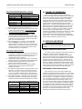
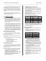
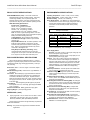
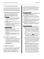
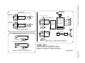
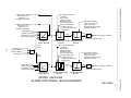
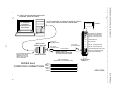
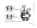
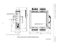
IntelliPack Series 832A Alarm User’s Manual Dual RTD Input ___________________________________________________________________________________________ Safety Summary - Symbols on equipment: 1.0 INTRODUCTION ! Means “Caution, refer to this manual for additional information”. These instructions cover hardware functionality of the alarm models listed in Table 1. Supplementary sheets are attached for units with special options or features. The information contained in this manual is subject to change without notice. Acromag, Inc., makes no warranty of any kind with regard to this material, including, but not limited to, the implied warranties of merchantability and fitness for a particular purpose. Further, Acromag, Inc., assumes no responsibility for any errors that may appear in this manual and makes no commitment to update, or keep current, the information contained in this manual. No part of this manual may be copied or reproduced in any form, without the prior written consent of Acromag, Inc. Table of Contents 1.0 INTRODUCTION ………………………………..…….. DESCRIPTION ………………………………………… Key IntelliPack 832A Features.…………………….. ACCESSORY ITEMS.…………………………………. IntelliPack Configuration Software....……………… IntelliPack Serial Port Adapter ..…………………… IntelliPack Cable………………………….………….. IntelliPack Interface Package....…………………… 2.0 PREPARATION FOR USE ….……………………….. UNPACKING AND INSPECTION.…………………… INSTALLATION.………………….…………………….. Mounting.……………………………………………… Electrical Connections.……………………………… 3.0 MODULE CONFIGURATION.……………………….. FIELD CONFIGURATION.……………………………. 4.0 THEORY OF OPERATION.………………………….. 5.0 SERVICE AND REPAIR ……………………………… SERVICE AND REPAIR ASSISTANCE….…………. PRELIMINARY SERVICE PROCEDURE..………….. 6.0 SPECIFICATIONS.……………………………………. MODEL NUMBER DEFINITION……………………… INPUT SPECIFICATIONS ……………………………. RELAY OUTPUT SPECIFICATIONS ……………..… SPDT Alarm Relay Specifications ………………… ENCLOSURE/PHYSICAL SPECIFICATIONS..…….. APPROVALS..………………………………………….. ENVIRONMENTAL SPECIFICATIONS….………….. FIELD CONFIGURATION AND CONTROLS……….. HOST COMPUTER COMMUNICATION…………….. SOFTWARE CONFIGURATION.…………………….. List of Drawings Simplified Schematic & Contact Protection (4501-627)... Functional Block Diagram (4501-694)……….…………… Computer to IntelliPack Connections (4501-635)...……... Electrical Connections (4501-638).……………………….. Interposing Relay Connections (4501-634).……………… Enclosure Dimensions (4501-631).……………………….. Table 1: Model Covered in This Manual Series/ -Options/Output/ Input/Type Enclosure/Approvals1 832A -0200 -Factory Configuration2 -C Notes (Table 1): 1. Agency approvals include CE, UL Listed, and cUL Listed. 2. Include the “-C” suffix for optional factory configuration. See Factory Configuration Order Form 8500-587 for this model. No suffix is required for standard configuration. Module programming, alarm operation, and use of the IntelliPack Configuration Software are covered in the IntelliPack Alarm Configuration Manual (8500-563). Page 2 2 3 3 3 3 4 4 4 4 4 4 4 5 5 6 6 6 6 7 7 7 8 8 8 8 8 9 9 9 DESCRIPTION The Series 832A Alarm is another member of the popular Acromag IntelliPack Alarm & Transmitter family. This alarm conditions two RTD inputs and provides two Single-Pole DoubleThrow (SPDT) electromechanical relay contacts. These alarms contain an advanced technology microcontroller with integrated downloadable flash memory & EEPROM for non-volatile program, configuration, calibration, and parameter data storage. Units are fully reprogrammable via our user-friendly Windows 95 or NT IntelliPack Configuration Program. Field reprogrammability without a personal computer is also possible with module push buttons and status LED’s. Once configured, these modules may operate independent of a host computer for true embedded monitoring and control. Each module provides two inputs for RTD signals. Sensor excitation, linearization, lead-wire compensation, and lead break detection are included. The module uses a high resolution, low noise, Sigma-Delta Analog to Digital Converter (Σ-∆ ADC) to accurately convert the input signal into a digitized value. Userdefined alarm setpoints are compared to this value and used to control built-in alarm relays. Each relay may have high or low setpoints plus deadband configured. Both the setpoint and deadband may be adjusted over the full input range of the unit. Relay actuation is user-selected for failsafe or non-failsafe operation. Relays may also be configured as latching, in which case a push button reset is required to reset the latch (this may also be accomplished via software control). Additionally, a programmed relay time delay may be applied to filter transients and minimize nuisance alarms. Each relay includes a yellow LED on the front of the module that indicates the high or low alarm condition. A green “Run” and yellow “Status” LED provides local feedback of the operating mode, field configuration status, and system diagnostics. Front panel push buttons are available to reset latched alarm relays and to facilitate field configuration in the absence of a personal computer. Page 11 12 13 14 15 16 IMPORTANT SAFETY CONSIDERATIONS It is very important for the user to consider the possible adverse effects of power, wiring, component, sensor, or software failures in designing any type of control or monitoring system. This is especially important where economic property loss or human life is involved. It is important that the user employ satisfactory overall system design. It is agreed between the Buyer and Acromag, that this is the Buyer's responsibility. Wide alarm functionality and convenient reprogrammability makes these alarms extremely powerful and flexible over a broad range of applications. These models may be configured as limit alarms, window alarms, on/off controllers, deviation alarms, peak detect alarms, and rate-of-change alarms. Other functions are also possible (consult factory). Windows 95 & NT are registered trademarks of Microsoft Corp. -2-