1
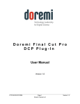
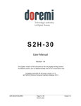
IMB and Barco Series-2 Projector Field Installer Manual Version 1.6 CRT.OM.001087.DRM Page 1 Doremi Labs Version 1.6 Table of Contents 1 Introduction ........................................................................................................................... 6 1.1 Introduction....................................................................................................................... 6 1.2 Purpose ............................................................................................................................ 6 1.3 Software Version .............................................................................................................. 6 1.4 Contact ............................................................................................................................. 6 2 Required Components for Installation................................................................................. 7 3 IMB Board Installation Procedure ........................................................................................ 9 3.1.1 HD-SDI Input.............................................................................................................. 9 3.1.2 HD-SDI Output ........................................................................................................... 9 3.1.3 HDMI Input ................................................................................................................. 9 3.1.4 IMB Board Installation ...............................................................................................10 4 ShowVault Server Installation ............................................................................................. 11 4.1 ShowVault Server and Projector Installation .................................................................... 11 4.2 Audio and GPIO Installation .............................................................................................13 4.2.1 Audio shielded CAT5 Cable Installation .....................................................................13 4.2.2 GPIO shielded CAT5 Cable Installation .....................................................................13 4.2.3 Audio and GPIO Pin-Out Information ........................................................................13 4.3 Device Manager Configuration ........................................................................................16 5 IMB Marriage Procedure ......................................................................................................19 5.1 Performing the Marriage on Barco Series-2 Projectors ....................................................19 6 IMB Troubleshooting Instructions ......................................................................................22 6.1 Check the Projector Version ............................................................................................22 6.2 Check the Diagnostic Tool GUI for Errors ........................................................................22 6.3 Check the PCI-Express Connection.................................................................................22 6.4 Check the Ethernet Setting ..............................................................................................23 6.5 Check the Communication with the IMB ..........................................................................24 6.6 How to Generate a Detailed Report .................................................................................25 6.7 IMB Configuration Script ..................................................................................................25 6.8 Hardware Configuration Diagram ....................................................................................26 7 Acronyms .............................................................................................................................27 8 Document Revision History ................................................................................................28 CRT.OM.001087.DRM Page 2 Doremi Labs Version 1.6 Software License Agreement The software license agreement can be found at the following location: http://www.doremilabs.com/support/cinema-support/cinema-warranties/ Hardware Warranty The hardware warranty can be found at the following location: http://www.doremilabs.com/support/cinema-support/cinema-warranties/ CRT.OM.001087.DRM Page 3 Doremi Labs Version 1.6 WARNING!! To prevent fire or shock hazard, do not expose this appliance to rain or moisture CAUTION RISK OF ELECTRIC SHOCK DO NOT OPEN CAUTION: ! TO REDUCE THE RISK OF ELECTRIC SHOCK, DO NOT REMOVE COVER (OR BACK). NO USER-SERVICEABLE PARTS INSIDE. REFER SERVICING TO QUALIFIED SERVICE PERSONNEL. The lightning flash with the arrowhead symbol superimposed across a graphical representation of a person, within an equilateral triangle, is intended to alert the user to the presence of uninsulated “dangerous voltage” within the product’s enclosure; that may be of sufficient magnitude to constitute a risk of electric shock. ! CRT.OM.001087.DRM The exclamation point within an equilateral triangle is intended to alert the user to the presence of important operating and maintenance (servicing) instructions in the literature accompanying the appliance. Page 4 Doremi Labs Version 1.6 CE NOTICE Marking by the symbol indicates compliance of the device to the EMC (Electromagnetic Compatibility) directive and to the Low Voltage directive of the European Community. The marking is indicative that the device meets or exceeds the following technical standards: EN 55022 "Limits and Methods of Measurement of Radio Interface Characteristics of Information Technology Equipment." A "Declaration of Conformity" in accordance with the above standard has been made and is on file at Doremi. HDMI The terms HDMI and HDMI High-Definition Multimedia Interface, and the HDMI Logo are trademarks or registered trademarks of HDMI Licensing LLC in the United States and other countries. CRT.OM.001087.DRM Page 5 Doremi Labs Version 1.6 1 Introduction 1.1 Introduction This document explains how to install the IMB into a Barco Series-2 projector. This document also describes the steps required to perform the “marriage” between the IMB SM and the projector electronics. Marriage is the process of engaging the DCI physical and software interlocks that enable the display of secured materials. The IMB requires a Doremi ShowVault server in order to work. This document also explains how to set up and connect the ShowVault server to the IMB board. 1.2 Purpose One of the key ideas behind marriage is that an authority figure examines the projector and ensures that it has not been tampered with before a marriage can be performed. This means that a person must be physically at the projector when the marriage is performed. It cannot be done remotely. To ensure an authority figure is present, there is a physical marriage button (or RFID key) on the projector which must be pressed in order for the marriage process to complete. Please contact your system administrator or Barco Technical Support for the required passwords. 1.3 Software Version This manual is intended for software version 2.0.10 and higher. This document is to be used with IMB SM 5.0.5 and higher. It is also to be used on Barco projector software version 1.3.41 or higher with TI (ICP) firmware 2.2.294 or higher. 1.4 Contact If in need of help or assistance, please contact Doremi Labs Technical Services: USA 24/7 Technical Services line: + 1-866-484-4004 Technical Services Email: [email protected] Europe 24/7 Technical Services line: + 33 (0) 492-952-847 Technical Services Link: http://support.doremitechno.org/ticketing Japan Technical Services line: + 044-966-4855 Technical Services Email: [email protected] Australia ~ China ~ India ~ Indonesia ~ Korea ~ Malaysia ~ New Zealand ~ Philippines ~ Singapore ~ Taiwan ~ Thailand Technical Services Email: [email protected] CRT.OM.001087.DRM Page 6 Doremi Labs Version 1.6 2Required Components for Installation Before beginning the installation, verify that the following cables are present: AC POWER CABLE ETHERNET CABLE Figure 1: AC Power and Ethernet Cables Figure 2: PCI-Express Cable CRT.OM.001087.DRM Page 7 Doremi Labs Version 1.6 Figure 3: IMB with Barco Front Panel Figure 4: Dallas Key CRT.OM.001087.DRM Page 8 Doremi Labs Version 1.6 3 IMB Board Installation Procedure The IMB board is illustrated below: Figure 5: IMB Board With Barco Mounting Bracket 3.1.1 HD-SDI Input Dual HD-SDI input compliant with SMPTE 292M and SMPTE 372M. HD-SDI input capable of supporting 3 GHz signals per SMPTE 424M. Mapping per SMPTE 425M is not implemented yet, but it will be available via a software update. The following are 2D formats that are currently supported on the HDSDI input of the IMB: Format\fps 23.98 24 25 29.97 30 47.95 720p 1080i X X X X X 1080p X X X X X 48 50 59.94 60 X X 3.1.2 HD-SDI Output IMB Revision A: HD-SDI output is not available. IMB Revision E: Dual HD-SDI output compliant with SMPTE 292M and SMPTE 372M. HD-SDI output capable of supporting 3 GHz signals per SMPTE 424M. Note: With the current firmware, the HD-SDI Output is not used. 3.1.3 HDMI Input The IMB incorporates High-Definition Multimedia Interface technology. HDMI®, HDCP compatible input, supporting deep color video up to 12-bit with the following formats: CRT.OM.001087.DRM Page 9 Doremi Labs Version 1.6 Aspect ratio\fps 23.98 24 25 29.97 30 47.95 48 720p 1080i X X X X X 1080p X X X X X X X 50 59.94 60 X X X X X X 3.1.4 IMB Board Installation Follow the steps below in order to install the IMB board inside the Barco projector: Make sure that the projector is powered OFF before installing the IMB. Line up the IMB board with the guiding rails on each side of the slot and insert the IMB board gently into the projector. Secure the IMB by installing the two screws in the panel. Figure 6: Side Panel Screws Turn ON the projector to begin the marriage procedure. Figure 7: Barco Projector ON Button CRT.OM.001087.DRM Page 10 Doremi Labs Version 1.6 4 ShowVault Server Installation 4.1 ShowVault Server and Projector Installation Follow the steps below in order to set up the ShowVault server: Connect one end of the Ethernet cable into the ShowVault "Eth0" socket and the other end into the Barco projector (Figure 8). Figure 8: Ethernet Cable Connection Connect one end of the PCI-Express cable into the ShowVault and the other end into the IMB board on the Barco projector (Figure 9). Figure 9: PCI-Express Cable Connection CRT.OM.001087.DRM Page 11 Doremi Labs Version 1.6 Connect two power cables into the ShowVault; it is the same for both the ShowVault3RU and ShowVault-4RU (Figure 10). Figure 10: Power Cables Connected to ShowVault Note: At this stage, please refer to the Barco projector user manual in order to perform any projector specific setting. Figure 11: Barco Series-2 Projector with IMB Installed CRT.OM.001087.DRM Page 12 Doremi Labs Version 1.6 4.2 Audio and GPIO Installation 4.2.1 Audio shielded CAT5 Cable Installation Plug one shielded CAT5 cable end into the top AES slot (RJ-45 connector) for audio channels 1-8. Plug the other end of the shielded CAT5 cable in the audio processor. Take another shielded CAT5 cable end and plug it into the bottom AES slot (RJ-45 connector) for audio channels 9-16. Plug the other end of the shielded CAT5 cable adapter in the audio processor. 4.2.2 GPIO shielded CAT5 Cable Installation Plug one shielded CAT5 cable end from the GPI slot into whichever automation controller is available or required. Take another shielded CAT5 cable and plug it from the GPO slot into whichever automation controller is available or required. 4.2.3 Audio and GPIO Pin-Out Information Figure 12: RJ45 Socket Pinout Example CRT.OM.001087.DRM Page 13 Doremi Labs Version 1.6 “1-8” denotes channels 1-8 “9-16” denotes channels 9-16 Figure 13: Audio and GPIO Connectors There are 4 RJ-45 connectors on the IMB front panel (two are used for audio and two are used for GPIO connection). The following sections have information related to the pin-out structure for the audio and GPIO. 4.2.3.1 Audio AES Pin-Out Information Channels 9-16 Signal Channels 1-8 Signal 1 Channel 9 & 10 plus 1 Channel 1 & 2 plus 2 Channel 9 & 10 minus 2 Channel 1 & 2 minus 3 Channel 11 & 12 plus 3 Channel 3 & 4 plus 4 Channel 13 & 14 plus 4 Channel 5 & 6 plus 5 Channel 13 & 14 minus 5 Channel 5 & 6 minus 6 Channel 11 & 12 minus 6 Channel 3 & 4 minus 7 Channel 15 & 16 plus 7 Channel 7 & 8 plus 8 Channel 15 & 16 minus 8 Channel 7 & 8 minus CRT.OM.001087.DRM Page 14 Doremi Labs Version 1.6 4.2.3.2 GPI Pin-Out Information 4 GPI on RJ45 Connectors: Pin # Signal 1 GPI 0+ 2 GPI 0- 3 GPI 1+ 4 GPI 2+ 5 GPI 2- 6 GPI 1- 7 GPI 3+ 8 GPI 3- 4.2.3.3 GPO Pin-Out Information 8 GPO on RJ45 Connectors: Pin # Signal 1 GPO 0 2 GPO 1 3 GPO 2 4 GPO 4 5 GPO 5 6 GPO 3 7 GPO 6 8 Ground Power ON the ShowVault by pressing the power button. Figure 14: ShowVault Server Power On CRT.OM.001087.DRM Page 15 Doremi Labs Version 1.6 Continue to the next section to configure the Device Manager. 4.3 Device Manager Configuration Run the Device Manager application to configure the Barco Series-2 Projector. Click on Menu → Doremi Apps.→ Device Manager. The following window will appear: Figure 15: Device Manager GUI Click the Add button. The following window will appear: Figure 16: Device Manager GUI - Add Device Window CRT.OM.001087.DRM Page 16 Doremi Labs Version 1.6 Click on Projector and then click on the Add button. The following window will appear: Figure 17: Device Manager Menu With Projector Added Select the "Projector model" and select "Barco" from the drop-down list and then select "Series-2." Enter the "Head IP" address for the projector. Click the "Save" button and then input the password to record the settings. Click the "test" button to verify the connection. The following window will appear: Figure 18: Test Screen CRT.OM.001087.DRM Page 17 Doremi Labs Version 1.6 Figure 19: Device Manager With Device Added and Configured When finished, the Barco projector should be ready for the IMB marriage. CRT.OM.001087.DRM Page 18 Doremi Labs Version 1.6 5 IMB Marriage Procedure 5.1 Performing the Marriage on Barco Series-2 Projectors Barco projectors use a combination of a “Dallas key” (an RFID transponder) and a series of button presses to arm the marriage. The procedure, shown below, consists of initiating the process using the Dallas key, then pressing the channel buttons in a sequence. It is not necessary to keep the Dallas key next to the security socket once the channel button backlight turns yellow. You only have five seconds to enter the key sequence. Figure 20: Dallas Key CRT.OM.001087.DRM Page 19 Doremi Labs Version 1.6 Figure 21: Barco Control Panel When the marriage is successful the backlight will flash green and then back to blue, and the projector tail light will turn from red to green. The system is now married and secured. Test the marriage by playing some encrypted content. Go back to the ShowVault unit and click on "Diagnostic Tool" by clicking "Menu → Doremi Apps. → Diagnostic Tool." Verify that there are no errors present. It should look like the image illustrated below in Figure 22. CRT.OM.001087.DRM Page 20 Doremi Labs Version 1.6 Figure 22: Diagnostic Tool - System Tab The ShowVault should now allow the playout of encrypted content. Test the marriage by playing 2D, 3D, encrypted, and non-encrypted content. Everything should function properly. If you are encountering problems then contact Doremi Labs Technical Support (Section 1.4). CRT.OM.001087.DRM Page 21 Doremi Labs Version 1.6 6 IMB Troubleshooting Instructions This section gives the steps to follow to support the troubleshooting that the installer (mainly Barco for Cinemark) has when installing IMB in the projector. It seems that a common issue is the failure for the ShowVault to connect to the SM, showing "missing" for the SM version. In any case, BEFORE replacing an IMB or trying another, the user(s) needs to get a Detailed Report from the Showvault and send it to Doremi Technical Support with the serial number of the Showvault (S/N sticker on the back of the unit). 6.1 Check the Projector Version This is to help determine if a new projector version is in use. 6.2 Check the Diagnostic Tool GUI for Errors Check the Serial Number, Software Version, Firmware Version, and SM Version. The color is to be asked too, as it has an important meaning: ◦ Black means that the value was read from the IMB. ◦ Red means that the value could not be read from the IMB and the last known value is displayed. 6.3 Check the PCI-Express Connection In a new Linux terminal, type: /doremi/sbin/mcsetup.out --get-serial (This command tests path 1). If the command returns a failure with "Mcore context", then it means the driver is not running. This is likely an issue with the PCIe either not connected or not seen. Have the PCIe cable unplugged and then replugged to see if it fixes the issue. If the PCIe unplug doesn't fix it, try to have the ShowVault and projector re-booted once. If this doesn't fix the problem, then go to Section 6.6 and get a Detailed Report. Note: As long as this issue is not fixed, performing the following steps will lead to failure. CRT.OM.001087.DRM Page 22 Doremi Labs Version 1.6 6.4 Check the Ethernet Setting a) Check the Device Manager: Check the Ethernet port configuration: /sbin/ifconfig Note the IP of both eth0 and eth1. Make sure a projector is set with the proper IP address. If the Device Manager doesn't have a projector setup, have them set it up and wait 30 seconds after they enable and Save it. Make sure other devices (like Jnior) are set with the proper IP address. Make sure those devices in Device Manager don't have the same IP addresses as the Showvault. Try to ping this IP address to make sure Ethernet connection is "OK". This tests path 2. If the ping fails the Ethernet is not connected properly. Maybe eth0 and eth1 are not set properly above. Or maybe the connection is not to the correct eth0 or eth1. b) check that the IMB has the proper IP address: Run the command: /doremi/sbin/mcsetup.out --get-ipconfig (this should return IP 192.168.254.246). Run the command: /doremi/sbin/mcsetup.out --get-ipconfig-ext (it should return the IP set in the Device Manager for the projector). If both IPs here are the expected ones then the PCIe is connected properly and the IMB is configured with the proper IP. If the IP is not correct, make sure the Device Manager is configured properly. If the commands return a failure with "Mcore context" it means that the driver is not running. See Section 6.3 (if step 3 passes, I would assume there is not a "Mcore context" failure. CRT.OM.001087.DRM Page 23 Doremi Labs Version 1.6 6.5 Check the Communication with the IMB Check the Ethernet: If the test in Section 6.4 passed, then run the command: /doremi/sbin/sbcsetup.out -a --get-temperature (this will exercise the communication with the IMB without the need of a proper synchronization of certificate). Also, this tests path 2 and path 3. If it succeeds it means that the hardware and network configuration are "OK". If it fails, it means that the IMB is not connected via Ethernet to the router internally of the projector. This is what typically would require a re-seating of the IMB (or modified front plate). Check the certificate configuration: Run the command: /doremi/sbin/sbcsetup.out --get-version If it succeeds, the Showvault and IMB are communication find and there is no problem. If the command reports a failure with "mismatch key", it means that the certificate in /doremi/etc/certs/mine is not the one corresponding to the IMB it is connected to. The easiest is to reboot the ShowVault. The synchronization of the certificate should be done during reboot. It might be necessary to remove all the pem files in /doremi/etc/certs/mine before the reboot. A more complicated (more complicated to have a technician on the phone to execute) but quicker way to fix is it: Run the command: /doremi/sbin/sbcsetup.out -a -f --verify -force-repair Again try the command /doremi/sbin/sbcsetup.out --get-version, if it succeeds the problem is fixed. CRT.OM.001087.DRM Page 24 Doremi Labs Version 1.6 6.6 How to Generate a Detailed Report If the issue is still not fixed generate a Detailed Report and send it to Doremi Technical Support (especially BEFORE replacing the current IMB). Along with the Detailed Report, send the following information: Site name and number, screen number, S/N of the ShowVault, and projector version. 6.7 IMB Configuration Script You can execute the script IMB_Configuration_check.sh which will run the commands outlined in Section 6.5. The script will be available in /doremi/bin. If it’s not, please copy it there. To run the script: Type: > /doremi/bin/IMB_Configuration_check.sh The script will run multiple commands. You have to press enter to proceed after each command. Below are the details of the script as the technician will see it. In case of a failure, the script will prompt the technician on the steps needs to be taken and it will exit. The technician needs to follow the script instructions and run the script until it passes all of them. Checking the IMB is seen on the PCIexpress IMB was found on the PCIexpress Continue (y/n)? y<enter> Checking IMB IP configuration IMB internal IP is OK Continue (y/n)? y <enter> Checking the Projector IP configuration Inet addr:10.10.1.120 Mask:255.255.255.248 Is this the correct IP addr for the projector (y/n)? y<enter> Checking the ethernet connection with projector The projector ethernet is properly connected Continue (y/n)? CRT.OM.001087.DRM Page 25 Doremi Labs Version 1.6 y<enter> Checking ethernet connection with IMB The IMB is properly connected Continue (y/n)? y<enter> Checking synchronization configuration The IMB and Showvault are properly synchronized. 6.8 Hardware Configuration Diagram Figure 23: Hardware Configuration Diagram CRT.OM.001087.DRM Page 26 Doremi Labs Version 1.6 7 Acronyms CRT.OM.001087.DRM Term Definition IMB Integrated Media Block LED Light-emitting Diode RFID Radio Frequency Identification Page 27 Doremi Labs Version 1.6 8 Document Revision History Date Version 11/19/2010 1.0 First draft performed on software version 2.0.10. 01/07/2011 1.1 All sections revised. 09/14/2011 1.2 01/24/2012 1.3 All sections revised. Updated to reflect changes in software version 2.2.2. Contact information revised. 07/17/2012 1.4 Section 3.1.1 HD-SDI information added. 11/06/2012 1.5 02/11/2013 1.6 Sections 4.2.1 and 4.2.2 updated to highlight usage of shielded CAT5 cables Minor revisions made to Section 3. CRT.OM.001087.DRM Description Page 28 Doremi Labs Version 1.6