1
*-*{
-l,i't
l
i
'f:"i''*i{
'- '
,
i
I
I
I
XP64O EPNOT PROCNAT{TEA
Fi:
usEns ilttruar,'
I
i
i
l
Copyright
GP If,DUS9BII$
t
a
:--
E; -,
t'
ELETTNOXICS
-
I
J
I
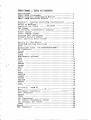
- T able
XP64O llanual
of Contents
.......e....o.............o..........1
IntrOduCtiOn
..............
XP540 EPROI{Programmgr
f ............1
. . . . . . . . . . . . . .. 1
progranning
ltoctule
XU52O Universal
.....................1
Xfi,51? EPROUEnulation
Module
Instruetions
1:
General 0perating
Section
Supply voltage
to note
Points
Using the llacblne
Layout of the XP640
........................
The Keypad
15 Character
Alphanumeric
Di splay
............
Video Display
. . o . . ..2
2
5
4
4
4
5
5
5
6
oo....
a a t a a a a o o a a a a a o o
.......
o............
r........
Video
Display
Fornat
o......
o......
....
o... r...
tED indiCatOrS
Diseretg
o...
. r..........
o. I o......
Version
numbgr
Flrmwarg
....................o.
Sockgt
Force
Insgrtion
Zeta
2:
Section
.. . . . . . . .. . . .. . . . . o . . . .. . ..J
EditOr'
... "'J
................
Functioas
Hgx
xP5 40 RAr{ E d i t i a g
STOP
Hexade c inal keys
FI{ (Punctioa)
( o r a 7 4 5 5 7 e 9 A B c D E r ) . . . . o. . r . . o. . . . 8
Cursor
EI{TER
Ct E A R
IiIEl,I ( t'tem o r y a d d f g s s )
a .
a
o
a
a
o
t . . .
a
a
a
a
a
a
a
t
a
a
a
o
a
a
a
a
a
a
a
a
a
o
'
o
o
t
t
t B
"
"
9
9
a o o a a a a a a a a a a a a a a a a t a a a a o a a a a a a a a a a I a a a o a a a a
T\Aml
I/./[IfA
PAGE
ASCII
o
a
a
a
a
a
O
a
r
i
r
.
.
........................r....!
.
a
o
a
a
a
a
o
a
a
a
a
a
a
a
a
a
a
a
o
I
o
a
.
a
a
o
o
a
a
. o o..
DEFINE
t.
r r.
r...
r.
a
'
a a
a a a a a o a a a a a o a a a a a a a a a o a a a o a a a a o a o a a a a a a a a o a
r t......
r r....
r.....
r......
I NVERT
..
SHIFT
o.........
t..........................
CO P I
FILL
.
a o .
.
.
.
.
.
.
.
.
.
i ....\4
a
a
.
r
r
.
I
r
r
.
r
.
.
.
a
a
|
.
.
.
.
.
.
.
r
.
.
.
.
.
a .
a
.
.
o a .
a
a
a
a
a
o
a
a a a o .
a
a
a
a
.
.
o .
a
a
a
r
r
.
SPI,IT
.. . . .. ...
SHUFFTE
.. ....
10
12
12
12
14
\
j
16
16
r. o . .. . . .. . . o. .. . .. . . . .. . . . 16
REPTACE
. . . . . . . . . . . . . . I o . r . . . . . . . o o . . . . . o . o r . o o . . . .17
. r....
o o.. r.................
o....
...17
.......
! . . . . o . . ... 18
o o. ....
. . . . .. . . .. .....
.. . .. ....
SEARCH
t.
INSERT
DEIETE
[QCK
PRINT
r.
o o..
o.
r........
r.
r.
r.
r.
o....
o..
o...
5:
o.
o.....
r o..............
f....18
. . . . ..
f dgntifigr
o............1
i.....
..............
PRO!{ Functiong
. . . . . . . . . . ..
E].ectroaic
. . o | . ...
. . . . . r o . . o . . . . ..
o.. r r r.....
. r...
r.......
PROc (frogran)
o..
VERIFY
STORE
r..
. . . . o . . . . . . . . . . . o . . . . . . r . . . r . . . r . c t . t . . . . . . . . 1$
Section
ll[gnu
o o.
r.
r r r.....
o........
o..........
r.
o. r r.
o..
o..
o.
r...
o.
o.
o......
..
...2O
..
.21
....21
...22
...2J
o............
o..
t
o......
....24
..26
r.. o. o................
...........
SUU (CUgcksum)
CRC (Cyelic
Redundancy
o...............
....2J
Check)
..28
r...
o.....
... o o o........
IBC (fffggal
Bit
Check)
BTANK
.. o. o..o.............................
o.. t ....2!
ERASE
. ..
. . ..
El{U (nrutate )
. ..
. ...
. . o.
. ....
..
.........
! o ..
..
o . | . o o ...
.....2)
a.
r....
....2j
a...
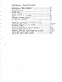
XP64O ilanual
-
Table
of
Contents
70
30
50
50
Section 4z XP540 Iaterfaces
XP540 Serial Data Transfers
Word Format
Sord
The Serial
Handshaking
0utput
SeriaI
Input
Serial
of
Remote Control
DI,Ii{P
,1
,1
,1
the
32
5t
XP640
o o. o ....J{
o.........
......
Set-Up
Paramgtgr
Intgraal
...76
o
.
.
....
o
.
.
.
.
o
.
.
.
.
.
.
.
.
.
.
.
PrOCgdUrg
CalibratiOn
.
.
..J8
o
.
r
.
.
.
.
o
.
.
.
r
.
.
.
.
.
.
o
o
.
.
.
.
Intgrfaeg
The Printer
.. o....A1
r.....
A1 /A2/A3
o o o. o.. .A4/L5
Formats
o o.......
r..
. '....
Data Transfer
Serial
A:
Appendix
........,....
F
o
r
n
a
t
D
a
t
a
Hex
Intel
ff
o
r
s
fr format
Exorcisgr
Motorola
A6
format
GP Binary
A7
f
o
r
n
a
t
L
i
s
t
Serial
(
r
u
r
u
n
x
)
o
.
A
B/ A 9
.
o
.
.
.
.
.
.
.
o
.
f
.
o
r
n
a
t
H
e
x
a
d
e
c
i
n
a
l
Tektronix
A
1
O/ L | 1
d
a
t
a
f
o
r
m
a
t
T
e
e
h
n
o
l
o
g
y
UOS
2/L1t
.
r
.
.
.
.
A
1
f
o
r
m
a
t
T
r
a
n
s
n
i
s
s
i
o
n
D
a
t
a
A
b
s
o
l
u
t
e
Signetics
.
.
t
A
o
.
r
t
4
/A15
P
e
r
c
e
n
t
a
n
d
A
p
o
s
t
r
o
p
h
e
C
o
m
m
a
,
S
p
a
c
e
,
ASCII
5
f
o
r
n
a
t
s
B
H
L
F
'
B
1
0
F
B
P
N
F
,
ASCII
6
fo rna ts
and Binary
DEC Binary
.
a
a
a
o
a
a
a
r.
o
a
a
o
a
a
a
a
aA
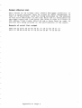
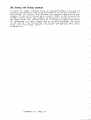
In.troduction
XP64O EPROU Progranner
to keep you ahead in=-ftrs-fasT-*o.ring
Tffiffi4-ri@
device
world
of programmable
technology.
It
combines both a
reliable
and
EPR0M duplieator,
video
RAM editor,
display
nost
comprehensive
input/output
make it
to
one
the
of
sophisticated
machines available
anywhere.
The RAM editor
can be "locked
at any tine
out"
to make the
XP540 a very
easy to use EPROM workstatlon.
This a11ows the
machine
to be used by unski 1 1 ed personne 1. for
1ow vo lume
production
runs.
The XP640 works equally
in elther
well
true stand-alone
node or
your
connected
to
computer
or
developnent
systen.
0nce
connected,
data ean be transferred
between the two machines and
programmer
the
can be remo te 1y contro 1 1 ed to
make i t an
part
integral
of your workstation.
XU52O Universal
Prograrning
trre xpe'dfs-expffirr
todule
trre xu52o
nodule
to
support:
BIPOLAR PROM from all
naj or manufacturers
S I N G L E C HI P E P R O M M I C R OCO MP U T E R S
P R 0 G R A M M A B I EA R R A Y t 0 G r C ( p . q , L s)
Xi512 EPROII Enulation
l{odule
provides
The emulation
option
memory.
Two nodules
can be connected
the
written
from
target
nicroprocessor
emulators.
up to
64k x B of
for 16 bit
side
to
Page
1
emulation
emulation.
a1low
its
Data can be
use
with
Section
1:
General
O:Sragi"g
Instructiqns
Suppll
Voltage
Machines
sttpplied
in the UK aad Europe are set to operate
at
24Ov, 5QHz supply.
A mains cable
is supplied
with the machj.ne.
The cores of the cable are colour
eoded as follows:
Live:
Brown
Neutral:
B1ue
piugs
The mains cable
into
the
located
on the rlghthand
side,
this
connector
are:
Earth:
Green/Ye11ow
XP640 via
the fused connector
rear
of the unit.
The pins
on
Earth
Live
Neutral
The unit
is protected
by a 5O0nA Antisurge
nains
connector.
Ensure mains voltage
is
attenpting
to replace
the fuse.
Us i n g t h e
To ensure
points:
lllachine
trouble
free
operation,
please
a/
0perate
b/
Do not
direct
locate
the
sunlight
c/
Ensure
no metal
d/
Disconnect
e/
D0 NOT switch
the
the ZIT socket
t/
Check the device
the ZIF socket
g/
Periodically
clean the ZIF socket
brush to ensure good contact
h/
the
machine
from
on a vibratj-on
nachine
parts
the
can
mains
machine
type
fuse located
disconnected
observe
free
any source
fa11
into
supply
on or
setting
Never
force
an EPR0M into
or
a
zero insertion
force
socket
Page 2
with
of heat
in
out
of
in
use
EPROM devices
when inserting
with
or
machine
when not
off
following
surface
near
the
the
in the
befor-e
EPR0Ms into
a stiff
ZIF
in
bristle
socket
it
is
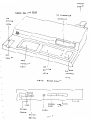
IIA I NS
CABLE
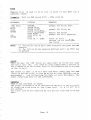
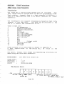
Layout
for
the
I
xP540
I
I
18
'lTF
STATUS
CHARACTER
DISPLAY
LEDS
PR OM
FUNCT I ON
KE YS
RAM
EDITING
CURSOR
KE YS
CONTROL
KEYS
XP64O
REAR
i
I
FUgE
R9232
PORT
MAINS
UIDEO
CABLE
ON./ OFF
gU I TCH
Page 3
PANEL
t
I
I
PARALLEL
PORT
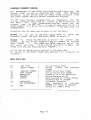
The Keypad
FE ffia'
is divided
into
three separat e sec tions .
(.) the right
hand section
is used for cursor
and keyboard
eont ro 1
(t)
the centre
section
for the Hex editor
(c) the left
h'and section
is subdivided
into
input/output
and
PROM funetion
keys
The keyfunctions
o f t h e m a n u a1 .
are
described
in
detail
in
the
later
sections
16 Character
A lphanuteric
DisplaJr
This is the on-board
display
and al1ows
the XP540 to be used
without
a video
monitor.
it
is
used
to
display
keyboard.
commands, messages, address and data information.
(current
The display
usually
shows the eursor
address
address
of
interest)
and RAM and PR0M data
at
that
address
a.s
i 1 1us trated be I ow:
OOOO
FF
cursor
address
RAM
data
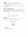
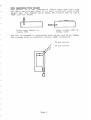
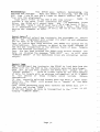
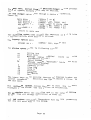
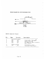
Video Di.splay
A composite
video
output
labe11ed
VIDEO at the rear
DIN socket
connections
is
of
(viewed
DIN
PROM
data
message
provided
at
the XP540.
from
machine
CONNECTOR
( REAR
1
2
1
4
5
READY
32
U I EII' )
Video out
ground
Signal
Video out
+5v
do not conneet
Lightpen
do not connect
Page 4
the
rear)
DIN
connector
Fornat
Video Display
four sections:into
is divided
The video display
type
and
device
selected
section
showing
1/
A status
i-nput / ou t pu t parame t e rs
display
line
to the on-board
line
sinilar
2/
Data entry
and
address
showing the cursor
dnd data display
Address
t/
the
ASCII
and
that
address
at
RAM data
PR0lrl and
equivalent
of the RAM byte.
cursor.
A hex dunp of 255 bytes with on-screen
4/
Discrete
LEI! indicators
with it.
ET'e progrffii@has
5 LEDs associated
the ZTF
to
applied
when power is
LED indicates
The active
or removed when the IED
EPROMs should not be inserted
socket
( tfre socket
the ST0P
can be powered down by pressing
is on.
key. )
I for
the
of pin
the position
two LEDs indicate
The other
device
depending on whether it has 28 pins or 24 pins.
selected
V ersion
l{unber
Firlrare
'f
BUSY'
NITIALISE
to the XP540 an
applied
When power is f i;sT
cheek.
a systen self
it performs
whilst
message is displayed
in the
nunber is displayeC
the Firmware version
When complete
number.
V X.Y READY'where X,Y is the version
message'XP540
Page 5
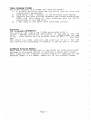
Force Socket
Zero Insertion
type
and will
force
ffie;6--l;;ertion
T1€ Jocte-s
a
n
d used
c
l
e
a
n
k
e
p
t
p
r
o
v
i
d
e
d
i
t
i
s
service
reliable
way to
t
h
e
c
o
r
r
e
c
t
The diagram be 1 ow shows
prope r ray'
the socket.
PROM into
Lever open, insert
remove PR0M
Lever closed,
fi rnly he 1d
or
PR0II is
The ZIF is designed to accomodate both 24 pin and 28 pin
PR0M orientation,
The diagram be low i 1 1us t rates correct
Page 6
28 pln
device
24 pin
device
give
in the
load a
PR0Ms.
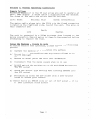
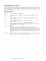
Section
2z
Ee:
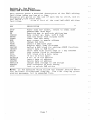
Editor
gives
of the XP640 editing
description
a detailed
This section
taken one key at a time.
facilities
and in
are given
on the use of each key by itself,
Exanples
with
other keys.
eonjunctlon
gives
RAM editing
of the available
a list
below
The table
facilities.
KEY
DECSRIPTION
STOP
HEX
FN
CURSOR
ENTER
CL E A R
ME}I
DATA
PAGE
ASCII
DEFINE
INVERT
SHIFT
COPY
FILL
SPTIT
SHUFFLE
INSERT
DELETE
R E P T A CE
SEARCH
t0cK
roturn
to normal mode
Power d.own ZTT socket,
data keys
Hexadecimal
editing
keys
key to activate
Function
& right
move cursor
up, down, left
buffer
from display
load hex entry
last
hex entry
clear
move cursor
to memory address
change hex da t a
a 255 byte page
select
display
ASCII dunp on-screen
& PR0M functions
define
a RAM block for editing
data in RAM block
invert
data with
cursor keys or to any address
shift
copy source block to destination
fill
block with a data value
16 bit
to I bit
spllt
8 bit
to 16 bit
shuffle
insert
data at address
delete
data at address
change data strings
to new strings
accurance
of data string
find
lock or unloek RAM edltor
in the examples which fo11ow the'DISPLAY'section
ilote:
display
display.
the on-board
fluorescent
The video
messages, but in expanded form.
sinilar
Page 7
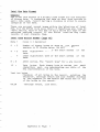
means
gives
STOP
the machine to norna 1
and return
This wi 1 1 stop any function
ST0P the ZIT
mode ready to accept new keyboard commands. After
is now
b
lock
p
r
e
v
i
o
u
s
d
e
f
i
n
e
d
1y
is powered down and any
socket
undef ined.
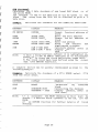
H B X A D B C T f , A LK E Y S
(Ot 21456?89ABCDEF)
These lower case keys
of hexadecinal
entry
accessi-b1e.
enabled
are only
otherwise
data,
when t.he XP640 requires
are not directly
they
rr (ruxcrrox)
key is used to enable
This
RAM editing
prior
to
any
or accidental
unintentional
Select
tsxanple:
key and must be used
any editing
prevents
use
Its
function.
e
d
i
t
o
r
.
use of the
page 34 for
disPlay
KEYPRESS
DI S P T A Y
MEANING
FN
PAGE
FN
P AG E
PAGE-54
1400 FF
is enabled
RAM editor
prompt for page number
enter the page number
is 3400,
address
cursor
data FF, no PROM data
54
ENTER
RAM
cuRson
to move
These are the arrow keys and ean be used at any tine
o
n
ce will
k
e
y
t
h
e
P
r
e
s
s
i
n
g
r
i
g
h
t
.
l
e
f
t
o
r
the cursor up, down,
d
o
wn will
k
e
y
t
h
e
c
u
r
s
o
r
p
o
s
i
t
i
o
n
.
H
o
l
d
i
n
g
one
move the cursor
r
e
q
u
i
r
e
d
.
a
s
t
h
e
c
u
r
s
o
r
m
o
v
e
continuously
Exarple:
Move cursor'right,
KEYPRESS
Right
arrow
up
MEANING
OOO1 FF FF
eursor
inerement
one
cursor
increment
16 ( t s c r e e n l i n e )
cursor
decrement
one
eursor
decrement
15 (t screen line)
001 1 FF FF
arrow
0010 FF FF
Up arrow
1eft,
DI S P L A Y
Down arrow
Left
down,
0OOO FF FF
Page
I
address
by
address
by
address
by
address
by
fote |
1/
The cursor address is shown followed
by RAM data and
P R O M d . at a
bo th are hex FF in this
example.
2/
The video
always
shows a dump of RAM data.
PR0M
data at the corresponding
RAIr{ cursor
address
1s also
pR0M data
shown.
If
the
is
shown as '--'
then
the
cursor
is outside
the range of the se lected
EPROM (i.".
no PR0M data is available).
Ef,TER
This i-s used during
the course of hexadeeinal
data entry.
E.g. address and data inf ormation,
Fi11 parameter,
lock cod.e.
'YES'
It is also
an inplied
k"y to reply
to questions
asked by
the XP640.
The XP540 will
only
act on the data entry
once the ENTER key
has been pressed.
CLEAR
This
can be used to clear
a hex entry
E.g. if
been made.
it
is also
used as an inplied'N0'key
response to q.uestions asked by the XpG40.
Exanple:
Move the
cursor
to
address
a mistake
has
for use in
O13F and correct
KEYPRESS
DISPLAY
MEANING
( rll;
o13c
A D D R ES S
ADDRESS-o1'C
CLEAR
F
ADDRESSO15
ENTER
01 3F DE FF
pronpt
for memory
enter address but
is wrong
last
entry
eleared
0K now enter
th
digit
eursor
address
is
data DE, PR0M data
MEM
ItEt{ (ilerory
mistake
address
last
digit
e
correct
01JF,
FF
RAM
address)
This
moves the cursor
to any RAM address
within
the 64k x 8
user RAM. The base address of the RAI'l is 0000 and corresponds
to PR0M (Ztp)
add.ress 0000.
The last
address
of the RAll is
FFFF.
The last
address of the PROM depends on the size of the
device selec ted.
Page 9
Move eursor
Eranple:
to
address
FFFF.
KEYPRESS
DISPLAY
MEANING
( rr ) r{EM
ADDRESS
ADDRESS_FFFF
FFFF FF
READY
pronpt
for new cursor address
enter the address
cursor
is now at FFFF, RAM
data is FF but no PR0M data
available
is
because
the
selected
device
is smaller
than the RAM
I'FF F
ENTER
f,otez
1/
Blanks
are
shown in
the PR0M data
field
i f the
cursor
adtlress is outside
the range of the PR0M.
2/
The cursor, can also be noved with the cursor contro I
keys or the page select
key.
I f no hex address entry
is nade and ENTER is pressed
5/
the XP640 wi 1 1 substitute
0000 as the required
address
as shown be 1ow.
Exanple:
Move cursor
to
address
0000
KEYPRESS
DI S P L A Y
MEANING
( FN ) IvrEM
ADDRESS-
ENTER
O O O OF F F F R E A D Y
pronpt
for
new
address
no address
entered
substitutes
0000
cursor
address.
PROMdata is FF.
cursor
so XP540
at
ne!r
RAM and
DATA
This comnand
address.
a1lows
keyboard
entry
P a g e 10
of
hex
data
at
the
cursor
;r'lit.lii
Change data
Exanple:
at
address
8000,
8001,
8002
KEYPRESS
DI SPLAY
MEANING
(FN)
ADDRESS_
pronpt
for
address
enter address
address
cursor
data is FF
prompt for data
enter the d.ata
noved
cursor
address r €trter
keep entering
will
increnent
entry
MEM
8000
ENTER
A D D R E S S8 0 0 0
READY
8000 FF
( F N) D A T A
01
ENTER
8000 FF
80OO FF
8001 FF
Ot
2t
BO01 FF
23
ENTER
45
ENTER
STOP
8002
BOO2
8OO'
BO05
ilote:
If no hex
XP640 will
FF
FF
FF
FF
to
01,
45
cursor
new
is
27,
8000,
RAM
entry
next
to
data
data,
cursor
after
each
+S
n-nAny
data
entry
terminated
entry
is nade & the ENTER key is pressed,
substitute
00 as the data as shown be1ow.
the
Exanple:
KEYPRESS
DISPTAY
MEANING
( F N) D A r A
ENTER
BOO' FF
8004 FF
LEFT ARROW
BOO5 OO
STOP
800,
prompt for data
made so XP640
no data entry
increments
enters
O0 and
curso r
ehange
review
data entry
data entry
is required
data
entry
terminate
functi-on
f,ote:
O0
READY
data entry
1/
keys
can be used during
The cursor
move to a new add.ress
mode is terninated
the ST0P key
2/
Data entry
with
Page 11
to
PACE
the
to the MEM key but positions
identical
alnost
This
is
p
l
a
c
e
d
p
a
g
e
.
T
h
e
c
u
r
s
o
r
i
s
2
5
6
b
y
t
e
t
h
e
s
t
a
r
t
o
f
a
a
t
cursor
v
i
d
e
o
.
t
o
p
l
e
f
t
.
o
f
t
h
e
at the
Exarple:
Select
page 83
( ptt
cursor
at
address
8r0O )
KEYPRESS
DI S P L A Y
MEANING
( F N) P A G E
81
ENTER
PAGE
PA GE-83
8r0O 49
pronpt
for page number
enter page
to
address
cursor
moved
no
is
8r00,
RAM data
49,
(Ufanks
PROM data available
in the PR0M data field)
READY
ASCIT
Provides
an ASCII dunp of the on- screen hex dump.
position
by a corresponding
is
shown
The eursor
(inverted
video)
in the ASCII
dump.
This
function
connected to the XP540.
usable with a video monitor
cursor
is only
DEFTtrE
block
define
function
for use with many of
This is the powerful
and
the PR0M functions
defines
the start
and editing
keys.
It
end address of a RAM block.
the
a block
using
There
are two different
ways to define
cursor keys or using the hex keys.
Exanple:
Define
the
block
0000
lFFF
using
the
hex keys
KEYPRESS
DISPLAY
MEANING
(fN)
DEFINE_
pronpt
address
of
for start
I
RAM block
address
enter the start
pronpt
for end address
enter the end address
block is now defined
press FN prior
to an edi ting
limits
are
command and block
shown
edit
command
terninate
DEFINE
0000
ENTER
1F F F
ENTER
FN
BIOCK 0000
BLOCK OOOO:
BL0CK OOOO-Tfff
B L O C K 0 0 O O - 1F F F
FN 0000-1 FFF
STOP
875D 43
READY
P a g e 12
(FN) key
the function
then
a block
is defined
If
1/
prior
to any
block
limits
the
d.isplay
always
will
those
reminder
that
is usef uI
command. ( tfris
editing
do so).
gditing
that can act on a block will
functions
bloek
a defined
can be moved through
2/
The'cursor
as a
by DEF-D (aefined)
the READY message being replaced
the block is defined.
that
reminder
keys
the PROM function
has been defined,
a block
If
5/
and the function
address,
for a R0M start
wi I 1 pronpt
act on the b1ock.
will
but
is undefined,
the block
When ST0P is pressed,
4/
and
are stil 1 available
linits
entered
the previously
(
f
U
)
E
N
T
E
R
.
DEFINE
by the key seq.uence
can be recalled
l
i
n
i
t
s
(i.e.
manual 1y entering
without
a block
define
entered. linits).
the block using the last
define
will
editing
to use the block
A block need not be defined
5/
(
f
U
V
E
R
T
,
will
as these
C0PY, FILL)
SHIFT,
functions
no
is
there
if
pronpt
and end addresses
start
for
n
ot
1
wil
but a PROM function
block
previously
defined
a
re
Iimits
block
their
addresses Iince
pronpt
for block
(
s
e
e
PROM
and end addresses
to be the PROM start
taken
function).
until
ST0P is pressed.
5/
A block remains defined
is
it
unless
of the block
is not part
The cursor
7/
as shown in the fo 1 1 owing
the b I ock,
used
to define
example.
fote.
data blocks
large
for defining
example is typical
The previous
p
r
o
g
r
a
m'
copy a
e.g. block
the PR0M functions
use wlth
for
to RAM ete.
PROM block
can be used to
example
shows how the cursor
fhe
following
blocks.
define
the
Define
Exarple:
bloek
2000 using
1I'FF
KEYPRESS
DISPLAY
I{EAN I N G
(FN)
ADDRESS_
pronpt
address
MEM
1T T F
ENTER
(fU) DEFINE
RIGHT ARROW
A D D R E S S1F F F
1F F F F F F F R E A D Y
DEFINE
20OO fF FF *1FFF
ENTER
B L O C K 1F F F
Iote:
The cursor
block
can
for
cursor
new
cursor
put cursor
a t 1F F F
prompt for block start
XP540
flxes
nove
cursor,
o
f the
t
a
r
t
a
s
s
address I FI'F
blo ck
the block has been defined
2000
be moved
the
in
Page 13
any
direction
to
define
a
ItrYENT
This is useful
on the data bus -
data in a RAM block
Inverts
buffers
which have inverting
Invert
Erarple:
the
data
in
the
block
microsystems
for
OOOO
001 1
S
KEYPRES
DISPTAY
MEANING
(fU)
DEFINE_
pronpt
address
for start
block to be inverted
address
enter
the start
pronpt
for end address
INVERT
BLOCK OOOO
BLOCK OO00-B L O C K O O O O - O Ot 1BIOCK OO0O-OO1
I N V E R TI N G
DONE
OO0O
ENTER
oo1 1
ENTER
of
the block
define
bu sy inve r t ing
complete
function
as part of the
was defined
the block
1/
In the exanple,
had previously
the block
however
if
INVERT function,
(using DEFINE), then no pronpts
would have
been defined
appeared for the block linits'
until
ST0P is pressed
2/
The block remains defined
ilote:
SHIFT
shifts
function
This
keys or direct
cursor
overwriting
without
is
transferred.
block
through
the RAM.
Exarple:
Shift
the
through
block
defined
addr€ss.
to the cursor
Data
of data.
or loss
as
side
to the other
a
block
0000
0001 to
address
K E Y P R E SS
DISPLAY
MEANING
(FN)
ADDRESS_
pronpt
address
MEM
FOOO
ENTER
(ff)
SHIFI
A D D R E S SF O O O
REIDY
FO00 C3
DEFINE
oooo
B r o c Ko o o o
ENTER
0001
ENTER
BLOCK O00O-BrocK 0000-0001 BLOCK 0000-OOO1
SHIFT T0 f000
ENTER
BUSY
F000 D9
DONE
Page 14
memory using the
Data is shifted
of the
in front
moves
the block
for
F000.
new
cursor
put the cursor at FOOO
pronpt
for block start
prompt
de fine
data
eursor
shift
for
block
end
the block
to
shifted
be
can
( see note )
position
complete
Iote
2
"
a hex
is displayed
1/
When the message "SHIFT T0
to where the block
is
can be mad.e as the address
entry
pressing
the
to be shifted.
ENTER (r" in the exanple),
is used. as the shift
address.
cursor
movements
the cursor
keys can be
2/
For'sma11
shift
"
message
used to move the b lock when the "SHIFT T0
is displayed.
the define
could
have been defined
using
The block
5/
function
When shift
is complete,
the block
remains
defined
4/
until
the
ST0P key is depressed
coPr
the RAM. When a
This command will
copy blocks
of data within
h
a
s
b
e
e
n
t
h
e
h
a
s
copy
completed,
source data
not been changed,
but has been duplicated
at the destination
address.
The copy
'intelligent'
command is
in
t
h
e
d
e
s
t
i
n
a
t
i
o
n
block
that
if
m
a
d
e
a
t the
overlaps
s
o
u
r
c
e
b
1
o
c
k
,
t
h
e
n
a
c
o
m
p
l
e
t
e
c
o
p
y
i
s
the
been
destinatiorrr
the
source
having
overlap
obviously
overwritten.
as part
The data block
can be defined
of the COPY command. or
usi-ng the DEFINE function.
Erarple:
at address
Copy the
10O0.
block
fronn 0000
to
0800
the
KEYPRESS
DISPLAY
MEANING
(FN) coPY
DEFINE
prompt
for
address
start
0000
ENTER
o800
ENTER
B L 0 CK 0 0 0 0
B L O C K O O O O:
BLOCK OOOO-OEOO
COPY TO FOO2
10 0 0
c 0 P Y T 0 10 0 c
ENTER
BUSY
1000 F4 1A DONE
pronpt
for
area
starting
source
block
block
end
pronpt
for
destination
to use the
address or option
adddress (rOOe)
cursor
1000 as
but
enter
address
required
been
copled,
block
has
RAM and
is at 1000
cursor
PROM data are different
tote:
exanple
the cursor
f n this
was at address F002 and would
have been used as the destination
address
if
ENTER had been
pressed when the 'COPY T0 F002 ' prompt had appeared .
Page 15
FILL
Menory
speeific
is
fill
value.
Erarple:
Fil1
used
the
to
fill
RAM block
a1 I
0125
or
part
of
0254 wi th
the
RAM with
0A
K E Y P R ES S
DI SPLAY
MEANING
(rr ) FrrL
o12'
DEFINE
pronpt
fo r
block
start
ENTER
B L o C K 0 12 5 BLOCKO125-6214_
B r 0 c K 0 1 2 7 - O 2 34
FILL WITH
FILL WITH OA
B U SY
DONE
0 12 3 O A
pronpt
fo r
block
end
define
pronpt
the
for
block
parameter
fill
o234
ENTER
OA
ENTER
ilote:
B r o cK o l z l _
a
with 0A
block is fil1ed
the
start
is
at
cursor
the block
of
the DEFINE
using
have been defined
could
1/
The block
function
the ST0P key
until
remains defined
2/
The fi 1 1ed block
is pressed
sPtrr
type
by the device
as specified
the RAM block
divides
This
in
i
s
s
t
o
r
e
d
two.
Al 1 data at even addresses
into
selection
i
s
s
t
o
r
e
d
d
a
t
a
odd address
and all
of the b1ock,
the lower half
in the top ha1f.
the RAM
15 bit
data had been loaded into
if
is that
The effect
(from the serial
2
can be
E
P
R
O
M
s
port)
t
h
a
t
so
it can be split
the
a
d
d
r
e
s
s
e
s
'
e
v
e
n
t
h
e
d
a
t
a
a
t
progranmed
one containing
:
data at odd addresses.
containing
other
SHUTTLE
This is the converse of SPLIT.
of shuf f 1e is to interleave
The effect
data in the lower
with
of the block
bit
shuffle.
by the
l,imits
are defined
The block
menu.
P a g e 15
the
half
device
data in the top half
to B
a 16 bit
i.€.
selected
from
the
(also
IISBBI
aee DETETB)
a free byte (FF ) at any address in the RA{.
Inserts
cursor
at
the
current
the RAM starting
The XP640 searehes
(f bytes at FF).
address for the occurance of 5 unused bytes
back
at FF is shifted
byte
found,
the first
space'is
free
If
address.
The data
the intervening
data to the eursor
through
the DATA function.
using
can now be nodified
address
at this
pressing
ENTER wi 1 1
0nce the INSERT mode has been entered,
bytes
as of ten as req,uired.
there
are no free
if
insert
free
a'N0
cleared,
SPACE'message is
bytes or the RAM is completely
displayed.
To exit
from INSERT mode, press ST0P.
data at address 001O.
Exarple:
Insert
exanple
assumes the RAM is eompletely
This
at address
except for 5 free bytes starting
KEYPRES
S
( fn )
INSERT
ENTER
with
data
DISPLAY
MEANING
0010 0O FF READY
at
cursor
fo"ition
insert
address
locating
free bytes
insert
complete
1oca t ing free by tes
no free bytes available
the
BUSY
0010 FF FF INS'
0 0 10 F F F F B U S Y
N0 SPACE
No data has been lost
f,ote:
byte
block
has been shifted
ro further
addressr
insertions
no more free space
DELETE
fi1 1ed
0010.
FF in the 5
or added.
The first
cursor
memory to
the
through
because there was
were possible
(t t so see IilSEBT )
there are at least
any byte in RAM provided
Deletes
5 bytes of
search for
address.
The XP640 will
free space above the delete
to the
and working
address
at the cursor
free
bytes
starting
address
the data at the cursor
top of the RAM.
0nce found.,
down one
data will
be shifted
be deleted
intervening
will
be added to the free bytes block.
address and an FF will
Erarple:
completely
0007.
De lete
data at 0005.
This exanple assumes the RAM is
at 0000
fi11ed
for
a data block
with
FF except
KEYPRESS
(r'N) Derntg
ENTER
ENTER
ENTER
DISPLAY
MEANING
OOO5 O0 FF READY
cursor
addresS
oooS oo FF
O O O S0 0 F F
0005 FF I'F
O O O SI ' F F I '
N0 SPACE
delete first
deLete again
and again
DEr'
DEI'
DEL'
BUSY
Page 17
is
at
the
delete
byte
possible no nore deletions
da ta f"on cursor to top
all
of RAU is at tr'F
-
NEPLACE ( a l s o
a
Replaces
occurances
to the new
The search
towards the
aee StsARCE)
data string
a new data string.
with
Any number of
of a string
ean be foutrd, (see SEARCH) and changed
string.
Maximum string
length
i s 10 b y t e s .
for'strings
begins
at the cursor
address
and works
top of the RAM.
Eratple:
Replace
the data strings
This example assumes that
the RAM is
the 2 strings
of 01 , 2t at addresses
KEYPRESS
at OO1O, OO20 to
45,
fil1ed
with FF except
001O, 0020.
DISPLAY
MEANING
0OOO FF FF READY
position
( r,,n
) RE'LA'E FrND
ll:-;:
cursor
to
start
;::"iri:il"1"r.
6 ' 1.
for
of
to be
found
o1 21
ENTER
4557
ENTER
FrND 01 23
REPLACEWITFpronpt
fo r new s t ring
da ta
REPLACEWITH 4r 67
HOWMANY SWOPS_
prompt
for
the
number
of
string
changes
H O W M A N Y S W O P S2
BUSY
busy searching
DONE
all
required
strings
have
been replaced
with
the new
s t ring
OO2O 45 FF READY
cursor
is
at
the
s tart
of
the
last
string
to
be
reDlaced
2
ENTER
STOP
Iote
2
SEARCE
1/
The maximum string
length
that
can be changed
bytes
2/
Any number of strings
can be replaced
(also
is
1O
see REPTACE)
Searches the RAM for the occurance of a specified
data string.
The search
starts
at the current
cursor
address
and proceed.s
'
until
a match is found with
the specified
string.
Subsequent or previous
string
occurances
can be found by usi-ng
the cursor
right
and cursor
left
keys.
P a g e 1B
Erarple:
Search the RAI,Ifor the data strings
3Q, 51 .
This example assumes that the RAM is f111ed with FF except
two strings
of 1Q, 5l at addresses 0010, 0020.
K E Y P R E SS
DISPLAY
MEANING
0000 r'F FF READY
position
at RAM start
cursor
pronpt
data
for string
( rlr ) SEARcH
3O t1
ENTER
FIND
FIND-30
BUSY
RIGHT ARROW
RIGHT ARROW
0 0 1 0 5 o F F N EX T
0020 30 FF NEXT
0020 10 FF BUSY
DATA NOT FOUND
tote:
bytes.
for
51
The maximum string
-
1 ength
search for first
string
found it at 0010
next string
found
no more strings
that
in
can be searched
RAM
for
10
is
LOCK
This
useful
comrnand will
lock
out the RAM edit or to prevent
personn e1.
The PR0M
aecidental
use or use by unauthorised
functions
and cursor keys are not inhibited.
the editor.
A 4 digit
code is req.uired to loek and unlock
Exaple:
Lock
and unlock
the
editor
with
c o d e O 12 1
K E Y P R E SS
DISPLAY
MEANING
(rr ) LOcK
o125
pronnpt for
ENTER
FN
L O CK
LOCK-A123
OO2O 3O FF READY
UNTOCK-
o12t
OO2O 'O
fhe
PBftf
all
editor
is locked out
pressing
FN asks f or unlock
code
editor
unlocked
Key
Thi-s keJr outputs
parallel
port.
for records
with
0nce
FF READY
code
data in the currently
The key requests
start
address fields
it also
parameters
have
been entered,
Page 19
selected
fornat
via
and end addresses,
asks for an offset.
it
will
print
the
the
and
data
I
I
I
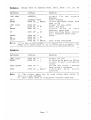
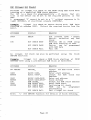
Section
7z
PROI{ Func tions
i
I
I
t-I
I
keys - a
the PROM function
below brief 1y describes
The table
in this
section.
explanation
is glven later
detailed
(""cept
on a
BtANK, ERASE, MENU, EMU) operates
Each function
u s e r d e f i n e d b l o c k o f d a t a i n t h e R A I V Ia n d d e v i c e s o c k e t .
on the
has been defined,
then the function
operates
If no block
RAM area.
corresponding
whole device and its
KEY
DESCRIPTION
IBC
Perforn
an i11ega1
bit
check" on the PROMusing
RAM block data
Calculate
the cye I ic redundancy
check value
for the eomplete PROM or a specified
RAM block
Calculate
the checksum of the complete PROM or
a speeified
RAM block
Copy PR0M data
at
starting
the
speeified
address to the RAM block
Verify
PR0M against
data
RAM and show error
Program the PR0M at any specified
address with
the RAM block
Performs a blank check on the entire
device
Electrieally
erase EEPR0Ms
Device table
Enulation
function
cRc
SUII{
STORE
VERIFY
P R OG R A M
BI A N K
ERASE
MENU
EMU
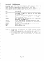
Note:
1/
The block
is defined
using the DEFINE key and defines
a RAI{ block
2/ If
il
bloek
is defined,
the function
will
operate on
the whole PR0II and the correspond.ing
RAM area
address
is outside
the range of the
3/ If the PROM start
deviee
selected
it
will
be rejected
and req.uested
again
Page 20
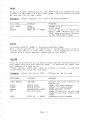
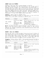
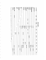
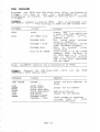
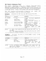
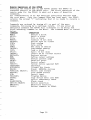
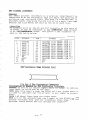
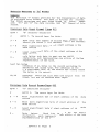
tenu
(device
selection,
Electronic
ldentifi-er)
type
to the particular
XP640 must be set up to correspond
The
The device type is selected
of EPROMto be read or programmed.
up, down keys or hex keys.
using the I{ENU.key and the cursor
the current
display
the MENU key the machine will
By depressing
to
defa,ult
as new will
The XP540 when supplied
EPROMselected.
value can be changed at
default
however this
2764 at power on
a n y t i m e ( s e e S E T P A R A M E T E R)S.
step
the cursor up or eursor down keys will
either
Depressing
the EPROMlist.
through
the display
0nce the req.uired dev j-ce appears in the display,
Press ENTER to
it.
select
A Device selection
by ENTER.
eurrently
The
section
status
can also
be made using
hex keys
the
device number always
seleeted
of the video display.
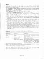
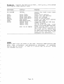
device
the correct
To select
listed
overleaf.
two tables
from
the
device
appears
in
the
to
the
of
side
the right.
the top of
the
menu, refer
hand
on the left
are listed
PROI,I manufacturers
to
devices are listed
page, and their
respective
at
for the XP640 is listed
selection
The correct
page in the 1ine labe 11ed DEVICE MENU.
followed
the
in the device menu.
duplicated
are apparantly
Some devices
2764A & 2764Q.
2764N, 2764f,
E.g.
nethod
(tf ,
A or a ) ref ers to the programning
I,
suf f ixes
The
EPR0M
the
by
as
stipulated
devices
by
those
req.uired
manufa eture rs
N
I
A
a
=
=
=
=
( iOts pulse )
Nornal program
programnlng
Intelligent
'A' version
of standard
INTET
Fuj itsu
Quick Pro programning
part
nethod
you
are
to natch the XP640 with the devices
is
inportant
It
program in the same way as
I 2764L does tof
progranning
E. g.
a 2754.
if
or inadeq.uate progr&mming nay result
to the devices
Danage
is used.
set!foS
the incorrect
I dentifier
Electronie
high speed programming
EPR0Ms now provide
ffiaffi
(".g.
INTEL's
identifiers
with electronic
along
algorithns
's
signature ) .
silicon
identifier,
SEEQ
intelligent
to
device
to match the selected
are provided
These identlfiers
p
r
e
v
e
n
t
nain use is to
Its
high speed. algorithn.
the
correct
n
o
n
on
progranming
algorithm
high
speed
of
a
the
use
t
h
e
(and thereby
possibly
under-program
devices
intelligent
device).
from the menu, the user is
device is selected
If an intelligent
ier.
identif
algorithrn
glven the option
to use the electronic
N0
"AUTO SELECT ?" key CLEAR fo r
tne pronpt
respons e
to
In
( don't
ier)- ot ENTER f or yes (use identif ier).
,r"" the identif
Page 21
r€
g
f*
o
c+
F
d
P
o
||
o
u
l|
H
x
?a
(:
@
t2
ul
H'
E
o
F
o
el
x(
o
FI
H
t
ut
()
tr|
||
t{
o
t
il
F
F
E
H
t
u
ti
tl
o
€
c'
!d
o
Fr
r
H
}|
GO
cl
trt
H
I
EI
||
H
F
el
u!
||
ri
€
}|
3a
H
ao
H
H
@
trl
H
tl
hl
cl
l,
I
I
tt
ct
I
l-t
ai
G
rt
o
{ht
o
o
€
It
t
tr
g
|t
t
o
It
o
F
o
o
!l
o
E
I
Fl
F
o
o
d
o
o
5
o
o
B
Ft
N
t
u
ru
vl
o
o
ts
P
o
F'
vt
o
o
Fn
t:t
o
B
N
il
t\)
-l
\tl
E
I
It
I
,t
D
\'
o
o
()
it
E
tu
r\)
-l
\tl
-l
\JI
@
td
F
o
r':l
@
o
E
g
I
Itt
lil
t;
to
lr
lFl
-tr
l\)
-l
tr
Il
o
Ot
c
iu
t
l\)
-:
47
=t
c) fu
N' -,J
--1 r
c) o\
Ol
@
tt
Ol
-T
c) c)
!t
tu ru
*l -.1
ro\
Or
E
\'l
tst
l\)
-J
t\)
-it
o\
Or
X
trt
4
5
Ol
t!
-l
F3
N)
\'l
o\
Clt
t\)
_jl
N
il
l>
lut
IF
lF
o\
o\
lr
C)
o\
ru
o
n
F
o
o
N
@
o
\n
\'
<;
C?
o
\' l\)
\Jr ol
6
rt
o
O\ O\
fr
vl
r\)
4
3(
c)
tu
vl
@
d
o
N
t\)
@
o
o\
(
Ol
@
(+
I
o
o
Or
z
o
Fn
F
@
o
o\
o
i
n
,f
It
o
a
T
o
\o
j
o\
{
H
o
o
a
o
zg
c)
l\)
\tl
\rl
t\)
€
-a,
f\)
\tl
vl
N
€
I
=
t\)
-.1
\,l
N
tt
HI
I
a)
N)
-l
\'l
l\)
r€
T
U2
N)
\tt
o\
5
trt
o
c
ru
tt
t\)
-l
o
\rl
f\)
-l
\,.
N)
tt
tu
-l
vl
f\)
q
|u
N)
-l
ul
N)
4Z
TT
C) C)
tu lu
-l -l
ovl
\rl N)
t\)
\o
ql
o\
T
o
N
\t
va
N
4
5
@
w
\tl
t\rl
fu
-N)
vl
\T
t\)
l:
\n
t1
t\)
-l
\rl
1\)
x
a
+
@
N'
-l
\rl
N
T
trt
!
t\)
-.1
vl
tu
l:
l!
=
ru
st
N
-.I
\rl
N)
ul
tu
tt
It
t\)
-l
N
-l
vl
N
C)
t\)
-l
\rl
n)
N
-il
vl
N
-l
ru
t,
()
tt
N
\t
Ch
a
ll
ll
ll
ll
tl
ll
A ll
ol l l
tl
rt\ t l
c- l l
C\T t l
ll
tl
ll
ll
ll
tl
ll
ll
ll
tl
ll
ll
ll
ll
tl
ll
A la
\o l l
n ll
(\l
ll
Fll
(\d
ll
ll
ll
ll
ll
ll
ll
ll
ll
tl
tl
tl
ll
ll
tl
tl
ll
tl
la
ll
tl
ll
tl
l
ll
tl
tl
o II
F tl
co l l
N
tl
ll
c- l l
C!
tl
ll
II
ll
ll
ll
II
ll
I
I
I
I
I
I
I
I
I
I
I
I
I
I
I
I
I
I
I
I
I
I
I
I
I
I
I
I
I
()
H
n|
tn
F
N
c,
ro
rn
N
F
il
\o
rt\
(\l
C)
t(\I
t
tr|
r
(.)
H
\o
tn
nl
F
G|
c,
@
N
F
AI
o
N
r-
AT
f.l
o
A|
F
N
t
o
c|
F
(\l
e,
r?
\o
F
c\|
Nl
HI
;l
II
c)l
F.l
>l
l|l
AI
i
\o
F
G|
\o
|r\
$J
tr(\I
@
ot
+
\o
F
(\l
a
I
lif
,o
o
-l
I
I
I
I
I
I
I
I
lr+
l\o
'Itr-
\o I N
tr-' t B
F
cl
,t
o
o
(,
r{
D
o
e
C\l
|.
o
fr
I
{(,
a
+.
5
t
I
I
I f:]
I
I
t
I
I lrl
llt
to
Its
rIl
tEl
t(J
IE
I t'r
to
ct r t r l
I irF
lrn
I
o
g
,y
q{
()
+
\o
FI
tr
P
@
o
p
e
C\l
@
$t
t-
col
=
o
o
ol
(\l
A
P{
{J
o
c(\,1
.P
A
O
OJ
AJ
c-.
(\I
@
.q
tC\T
--
=
Fl
+,
o
o
t<
tr
o
o
o
d
€
qt
sf
rrf \o
\o c)
c- r-.
NN
EFGq
6
+,
qt
.Et
Ttr
o
k
o
t'
a
P
C)
(!
qi
I
\o
t.-
=
EI
(\l
|__,*
H
o
U
4
o
c$r
D
F
T
L".-,
I
I
I
I
I
I
I
I
I
I
I
I
I
I
I
I
I
I
I
I
I
I
I
I
rlt
I g:l
I l.l
IH
I}?
tl3
th
|tt
E
x
<t
\o
col
,
Fl
r\
I
s
-t \o
\o r-c) ol
c-'@
c\l r+
a=
;E ;E
A.f
S\O
\oo
F- trNot
AC
Pr p{
*
\t)
r-(\l
V)
R
t
\o
tr-(\l
t
a
T
E
g7
EI
c,)
{
H
!t
tt
s
3.
I|
H
trl
m
E
o
F.
qi
sf
\o
cGI
I
\o
q
$\o
\oo
tr- tr-
\o
R
C\r
I
oJ@
R&
>l
ll
ltr
o
frl
o
ar
I
I
I
()
o
H
l'.
c)
E
I
H
H
o
()
o
trl
-
Er
F
gt
I
l-t
Fl
rt
sl
t
T
l.o/
u2
<,
sl
n
u2
a
EA
(t
o,
x
Lt
lr
A
rf
\o
tc!
E
-E{
n
H
It
tn
o
?.
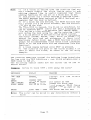
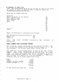
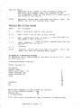
PROC
(pnocuu)
PRo!.{ with
the
Prograns
bi.t
check to
illegeI
is conplete'
progranning
tlisplayed
perforni-ng
an
after
RAM block data
progrannability.
0nce
test
for
the ?ROMis verif leal and a checksun
Data is prograrnned into
P r o g r a n a c o n p t e t e P R o ! I.
Eraiple:
a t P R o l t Ia n d R A I { a d d r e s s 0 0 0 0 .
The device with RAM data startiag
KEYPRESS
DISPLAY
MEAN I NG
STgP
READY
PRQG
BIT
any block definition
Renove
p
o
w
e
r
down the ZIF socket
&
is
ZTF
check,
bit
Fail
powered down
progra-m
pass '
eheck
Bit
p
r
o
g
r
e
s
s
cycle in
complete ' verify
Programning
pass, checksum disPIaYed
enter
to
Fail
Program,
m
o
d
e
verify
is at RAM & PROM
error
First
is
RAM data
0024,
address
(
E
r
r
c
r
i
s
F
F
.
d
a
t
a
00, PROM
b
e
c
a
u
s
e
a
v
a
i
l
a
b
l
e
i
s
data
a
d
d
r
e
s
s
e
s
&
s
t
a
r
t
ROM
RAM
a r e t h e s a m e) .
CHECKFAIL
P R O G R A MB U S Y
P R O G R A M= F 0 1 E
P R 0 G R A MF A I L
OO24 00 FF VMODE
Note:
Exarple
starting
See VERIFY funetion
the
Progran
at PR0M address
for
of
a deseription
RAM block
0000.
8000
801 0
VMODE.
into
the
KEYPRESS
DI SPLAY
MEAN I NG
( FN) DEFINE
DEFINE
prompt
blo ck
for
s tart
8000
ENTER
801 0
ENTER
PROG
OOOO
ENTER
BLOOK 8000
BIOCK 8O0O:
B L O CK 8 0 0 0 - e 6 t o
BLOCK 8000-801 OROM START
ROM START-OOOO
P R O G R A I ,BI U S Y
P R O G R A l j=l C D O F
pronpt
for
end address
Page 22
PR0M
of
address
RAM block defined
pronpt
fo r RQM add ress
'
block program in progress
&
block
program
PASS
checksun dlsp'layed
.
VERIFI
the ?RoU.
If ao block
Conpares a user-alef ined RAll block rith
v
e
"
i
f
i
e
a
l
a
g
a
i
n
s
t
RAll data
t
h
e
n
t
h
e
e
n
t
i
r
e
P
R
0
U
i
s
is defined,
a
a
l
d
r
e
s
s
a
t
0
0
0
0
.
starting
data then a PASS nessage
the RAlt and PRolt coataia ideBtical
If
to verify
thea verify
node is
If the PRoM falls
is tlisplayed.
etrtereal to tlisplay error (lata.
points sppllr:
node the followiag
once ia verify
1/ Tf the cursor lies outside the RAM area corresponding to the
noved to addregs OOOO.
P R o l ' {i t 1 s a u t o n a t i c a l l y
a
l
r
a
ys startg fron the current cursor
T
l
:
e
s
e
a
r
c
h
f
o
r
e
r
r
o
t
s
2/
position
proceeding to the top of RAU.
error encouatered atral this is
shorE the first
3/ The dlsplay
the aew cursor posltlon.
4/ L]-I erro rs on a v ideo page are showa, ead these are sho$n ag
the cursor bei.ag shown as a highlighted
highlighted
bytes,
nibble.
and cursor rlght keys can be used to nove to
5 / T r j - ec u r s o r l e f t
the previoug or next error occurance - if no nore errors are
present the display ri.11 show an 'oUT 0F RAM' nessage.
errors are present'
6/ If a block has beea defined ancl verify
fron the start
the search for the first
error always starts
address of the block. 0n1y block d.ata is shosn - other bytes
not i-n the block are shoru as blanks ou-screea.
7/ Pto vitled that the RAII block sta"t ad.dress is the sane as the
ROII start address, then actual error data is shown.
the RAM error
addresses,
If
the b locks
are at different
address is always shown along with RAM and PROM data at that
s;ne ;Ad re s s .
Verify
Exarple:
a complete
PROMagainst
ROM data.
K E Y P R E SS
DISPLAY
MEANING
STOP
READY
V E RI F Y
V E RI F Y P A S S
block
any unwanted
Renove
definition
PR0M
contain
RAM
and
identical
data
are present
Errors
the
fron
started
The search
position
current
cursor
is
the new
error
at
First
at 7024, RAM
cursor
address
data is 00, PR0M data is FF.
VERIFY FAIL
1024 00 FF VM0DE
Note:
cursor
of
Part
block
use the cursor
left
key to view
right
keyto view next errors.
a PR0M can
i1 lustrated
previous
be verified
with
any user
in the fo1 lowing example.
Page 2t
errors
and the
specified
RAM
Eranpfet
starting
at
the RAM block
Verify
PR0I{ ad dre s s 0000 .
8000
8010 with
a 27 16 EPROM
KEYPRESS
DISPTAY
MEANING
FN DETINE
DEFINE-
8000
ENTER
8 0 10
ENTER
VERIFY
0 0 00
ENTER
Br0cK 8000
B r 0c K 8 0 0 0 :
BLOC
K 8 0 0 0 - A 6 tO _
B L o C K8 0 0 0 - 8 0 10
prompt
for
RAM block
start
address
enter start
address
pronpt
for end address
enter end address
block is no.w defined
pronpt
for ROM s tart
address
enter ROM start
comparing PR0M and RAM data
verify
complete
verify
node entered,
first
error
i s a t R A I t ' la d d r e s s 8 0 0 1
(PnOu address 0001 ). This is
the first
error
to
address
be found,
but no error
data
is available
because the RAM
block
start
and R0M start
addresses are different.
ROM START
ROM START-OOOO
VERIFY BUSY
VERIFY PASS
VERIFY FAIt
BO01 00 00 VMODE
STORE
d a t a f r o m t h e P R O M t o t h e R A Mr v e r i f l e s P R 0 M a g a i n s t
E@s
RAll
data
then
caleulates
and displays
a
checksum.
complete
A
device can be stored,
or part of a device nay be stored
using
the DEFINE func t i on .
Page 24
Era
ple:
ST0RE a 2754 into
the
RAM.
KEYPRESS
DISPLAY
MEANING
STOP
STORE
READY
STORE BUSY
any RAM block
RAM
PROM to
the
address
at
RAM
and
verify
0ooo,
then
checksum the PROM
& checksum
Store
successful
displayed
( faif
unsuccessful
Store
verify)
node now
entered
Verify
left
or
use
the
cursor
view
right
keys to
cursor
(Pirst
error
i.s
data.
error
is
00,
at
0044,
RAM data
PROM data is FF).
Un-define
the
Co p y
starting
STORE = 2D9A
STORE FAI t
0044 00 FF VM0DE
node and how error
of the verify
For a description
1s displayed,
see VERIFY func tion .
Note:
1/
data
Part of
below:
a P R O l t ' cl a n b e s t o r e d
STORE a PROMblock
Erarple:
2038 .
to
any RAM s tart
O O 10
O O 1F t o
address
the
as
RAM block
shown
2O3O
KEYPRESS
DISPLAY
MEANING
FN DEFINE
DET ' IN E -
2070
ENTER
K 2030
BLOC
B L 0CK 2 0 7 0 - _
207F
ENTER
STORE
B L 0 CK 2 0 1 4 - 2 0 5 8
BLoCK 2010-205r
R O I . TS T A R T -
oolo
R0t1sTART 0010
S T O R EB U S Y
start
Pronpt
for RAM block
address
Enter block start
end
Pronpt
fo r
RAM blo ck
address
Enter the block end
Block defined
of
ROM start
Pronpt
for
block
E n t e r R 0 M st a r t
&
data
block
Stores
the
verifies
d.isplay
Store
successful,
RAM block cheeksum
S tore unsuccessful
is
at
error
RAM
First
but both PR0M
address z0j4,
thi s
and RAM da ta are AA at
( a"tua1 error
address
data
be shown be caus e the
canno t
do
no t
RAM & PROM blocks
at the same address).
start
ENTER
RAMC'SUM = 0769
S T O R EF A I I ,
2014 AA AA VMODE
Note .. 1/
2/
See
See
DEFINE. function
VERIFY funetion
for
for
more details
on block defining
node)
details
of VMODE (verify
Page 25
I
I
r
tt-
r
t-
r
t-
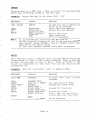
SUI{ (Checksur)
the 2 byte checksum of any length
Caleulates
RAM block
or
of
PROI{.
the entire
is the 16 bit
addition
the
checksum
of all
tbe bytes
in
the
The .carry f rom the 15 th bit
block.
is discarded
2
to give a
byte vallle.
the
checksun
for
the
RAM block
0 0 0 0 - 1F F F .
K E Y P R ES S
DISPLAY
TIEANING
FN DEFINE
DEFINE_
o0 0 0
ENTER
BLoCK OO00
B L O C KO O O O :
1FFF
ENTER
BtocK 0000-1FFF
BtocK oo00-1FFF-
S Ul,I
R A I , IC ' S U U B U S Y
R A M C , S U I I T= F O 1E
Pronpt
for start
address of
block
Enter the s tart
ad.dress
Pronpt
fo r end
address
of
block
Enter end address
Bloek
now
de fine d
and
highlighted
or-sereen
Calculate
checksun
(fOtU
Display
ehecksum
in
this
case )
Note:
r
tt-
CaIculate
Erarple:
1/ Once a bloek has been defined
it
is highlighted
oD.sereen and shown by DEF-D ( aefined ) oa the fluo"eseent
display.
To elear
the bloek definition,
press ST0P.
2/ The block eould have been defined
using the
cursor
(See DEFINE function)
keys.
.
A
eomplete
device
f ollowing
example.
Erarple:
from the
can be q.uickly
Calculate
the
d e v i c e m e n u) .
ehecksun
ehecksunned
of
as shown in
a 2715 EPR0M ( selec t
the
27 16
l-KEY PRE S S
DI S P L A Y
MEANING
ST O P
READY
'Un-define'
S Ul,I
C H E CK S U I { B U S Y
C H E C K S U I {= 2 5 A D
Note:
aoy
unwanted
bloek
Ca l c u l a t i n g
the ehecksum
( eeAD in
Display
checksum
this
case )
1/
To
caleulate
the PR0M checksum no block
m u st
be
defined
a defined
block operates
o n t h e R A I , ,I
no t the
PROM.
2/
See DEFINE function
for further
details
of
block
def ining.
Page 25
CBC (Cycli.c
Reduadancy
Check)
is a
complex
eheck
redundancy
cyc lic
The
'describe'
a block
t
o
produces a uniq.ue number
but is
a
c
h
e
c
k
s
u
m
,
t
o
in many. respects
sinilar
i
n
t
h
e
d
ata will
a
n
y
c
h
a
n
g
e
s
a check value si-nce
(
f
h
i
s
case
a
l
w
a
y
s
t
h
e
n
o
t
i
s
a new CRC va1ue.
calculate
will
The
CRC function
for the
p
r
o
d
u
c
e
v
a
l
u
e
a
block or
Ca l c u l a t e
EraEpIe:
the
CRC for
a value for
PR0M.
entire
the
whieh
algorithn
is
it
of data.
as
more reliable
always produce
with checksum).
any
RAM
length
R A M b l o c k " O 1O O - 0 1 F F .
KEYPRESS
DISPLAY
MEAN I NG
FN DEFINE
DEFINE_
0100
ENTER
BLOCK 0100
BIOCK 01OO-_
01 FF
ENTER
B I O C K 0 1 O O - 0 1F F
BL0CK 0100-01 FF-
CRC
nAM CRC BUSY
R A M C R C = E F5 7
address of
for s tart
Prompt
block
Enter block start
of
address
for end
Pronpt
block
Enter block end address
&
defined
now
Block
on screen
highlighted
CRC of block
Ca l c u l a t i n g
is
the RAM blo ek
CRC fo r
(EF57
this
in
displayed
case )
Note :
is
the STOP key
unless
block remains defined
1/
The
pressed.
using the cursor
2/
The block could have been defined
keys (See DEFINE sectlon).
Caleulate
device menu).
Eranple:
Eo-e
the
CRC of
a
27128 EPROM (
""Iect
27128
KEIPRESS
DISPLAY
MEANING
SfOP
READY
CRC BUSY
CRC = E5CF
block
Clear any defined
P R 0 l ' 1C R C
Calculating
is
the
PROM
for
CRC
(n lcr
ttii.s
in
disprayed
case )
cRc
Note:
block
Bo
P R O M C R Cr
the
calculate
To
1/
a defined
block operates
previously
defined
R A M, n o t t h e P R O M.
Page 27
must
on
be
the
IBc
(fflesal
Blt
Check)
an ilIegal
bit
Perforns
c h e e k o n t h e P R O I I u s i n g R A I I {b l o c k d a t a
starting
at a specified
PROM start
addr€ss,
it
that
all
checks
is a cheek for programmability
The
IBC
in
the
bits
in the ctdvice can be set to the req.uired pattern
RAM.
programmed 'O' eannot be set to a '1 ' without
A
exposure to Uv
(npnOMs), or electrical
(UnpnOMs).
llght
erasure
Exarple:
ETETing
m e n u) .
at
Illegal
address
bit
device
check an entire
OOOO. (Sef ect the required
with
RAII data
deviee f ron the
KE Y PRE SS
DISPLAY
MEAN I NG
ST0P
READY
IBC
BIT
CHECK BUSY
BIt
CHECK PASS
BIT
CHECK FAII
powered
down
insert
ZIY
devicer
any
RAM
uo-define
block
Perforn
PROlt{ using
fBC on
at 0000
RAM data starting
programmed
Device
ean
be
with RAM data
Fail
IBC
An
illegal
bit
DEFINE function:
Exarple:
address
check
Illegal
0200 using
can also
bit
check
a pre-defined
be perforned
using
the
at
a PROM block starting
RAM block at 0400-0500.
block
PROM
KEYPRESS
DISPTAY
MEANING
FN DEFINE
DEFINE
0 40 0
ENTER
BLOCL 04OO-_
Pronpt
for RAM block
start
address
address
Enter start
pronpt
end
for
RAM block
address
Enter end address
Bloek defined
Pronpt f or ROM s tart
adilress
Enter PR0M start
bit
eheck
Performing
programmed
PROI{
be
can
suecessfully
bit
check
Fail
illegal
Br0cK 0400
0500
ENTER
IBC
0200
ENTER
Bt0CK 0400-0500
B L O C K O 4 O O- O 5 O O R 0 1 , 1S T A R T
ROM START-O2OO
BIT CHECK BUSYBIT CHECK PASS
BIT
Note:
1/
CHECK FAII
See DEFINE function
for
Page 28
details
of
block
defining.
BLAXT
bytes
device.
If all
a blank check on the selected
Performs
m
e
s
s
a
g
e
i
s
d
i
s
p
l
a
y
ed.
P
A
S
S
a
d
e
v
i
c
e
a
r
e
H
e
x
F
F
,
the selected
in
EBASB
a
EEPR0M then perforns
erases the selected
EIectricalIy
g
i
v
e
m
e
s
s
a
g
e
.
a PASS or FAII
check to
any
an
EEPR0M
nus t
be
type
selec ted
device
The
g
i
v
e
m
e
s
s
a
g
e
.
will
an error
selection
blank
o the r
ErU (rrulale)
the
Module via
XM512 Enulator
RAII{ data to the optional
Sends
a
s
the
l
e
n
g
t
h
t
h
e
port.
i
s
s
a
m
e
parallel
The
data
sent
0
0
0
0
.
a
t
a
d
d
r
e
s
s
d
e
v
i
c
e
a
n
d
s
t
a
r
t
s
sleeted
eurrently
RAM (6qU x 8) is 6 second,s.
the entire
to transfer
tine
Typical
Page 29
SECTIO| /+
XP64O Interfaces
XP64O Serial
Data Traasfera
Introduction
The
XP540 has a bidirec tional
R S2 1 2 C p o r t a s
standard .
This
port
nay be used to receive
data for device progranming, from a
host computer,
transnit
data to a host computer or printer,
or
used as a communications
link
t o a n R S2 t 2 C t e r m i n a l
remote
for
operation.
The
RS2t2C port will
support
transmission/reeeption
baud rates
between
110 and 19XZ baud.
The data xnay be received
in
any
one of 15 formats,
and transmitted
in 16.
These
1
2
3
4
5
5
7
B
9
10
11
12
17
14
15
16
fornats
are:
MOS TECHNOLOGY
SIGI{ETICS ABSOIUTE
TEKTRONIX HEXADECIMAL
BINARY
DEC BINARY
ASCII HEX COMMA
A S CI I H E X A P O S T R O P H E
ASCII HEX PERCENT
ASCII HEX SPACE
BIOF
BHLF
BPNF
( Output only )
LIST
M O T O R O L AE X O R CI S E R
INTEL HEX
GP BINARY
These formats
are all
A
full
specification
appendix.
The speed ,
made using
Yord
in detail
in
serial
ni11
Appendix A.
be
found
in
format,
word fornat
and handshaking
the XP640 menu selection.
Fornat
START BI TS
STOP BITS
DATA BI TS
PARITY
lhe
described
of
the
Serial
The XP640 word
fornat
selec tions
the
are
is:
1
10R2
7 /8
0 N/ 0 F F/ 0 D D/ E V E N
yord:
--'t---'f
o
- 12V
1
2
e
\
ID LIHG Ur]rC
LgB OF DATA
\
3TART 8 IT
Page 70
ll
lf
1
5
I
7 !e
lr
oPTroNAL gt h\Brr\
i
t;;il;
OPTIONAL
PARITY
BIT
Handshaking:
The
XP64O uses
hardware
handshaking
via
CTS/DTR and .DSR/RTS.
When the XP540 is receivlrrg r the DTR and
(pin 20 and pin 4) nust be used to control
RTS line
the
data
flow into
the programmer.
A
high 1eve1 (+1 2v) on the RTS & DTR line
indicates
ready
to
(-l ev; indicates
recei.ve. A low level
not read.y.
Before
the XP640 will
data,
output
the input
handshake
lines
CTS and DSR, (pins 5 and 5) nust taken to a high 1evel (> 5v).
If
a
handshake line
changes state
during
a
byte,
the
XP64O
expeets the transfer
to continue
until
the end of the next stop
bit.
Serial
0utput,
tr['e-TF6&
serial
output key instruets
the programmer to
output
data.
progranmer will
The
pronpt
for start
and end addresses
for the data to be transnitted
Onee the linits
have been entered,
the XP540 will
pronpt
for an
offset
address.
This address is added to the aetual
address of
the data and transmitted
in the address field
of those
formats
that have address information.
Once
this
has been entered
the XP54O will
ei ther transnit
the
data
and
display
the message "DONE S0UT"
opr
it
will
show
" T I I t ' I E O U T E R R O R"
if
the handshake lines
are preventing
serial
output.
Serial
Input
The
serial
input key instructs
the XP54O to load data from the
R5252 port into
the RAM in the currently
selected
data format.
0nce
the
key has been pressed the Xp540 wil 1
prompt
for
an
"0FFSET ADDRESS".
This is either
taken as the start
address
of data for fornats
with no address information,
or it
is added
to
the
address
of
those
f orma ts
which
i.nelude
address
inf ormation.
If
the
currently
selected
fornat
does not have a
byte
count
facility'
the
XP640 will
prompt for a "1ength"
of
the
data
being input.
Once
these parameters
have been entered
the XP54O will
load in
the data and display
"D0NE".
If for any reasonr tro data is transnitted
to the XP54O, it will
dispray
"TrME0UT ERRoR".
Page 31
Berote Operation
of the XP54O
Pressing
t h e R e n o t e K e y o n t h e X P 6 4 0 c a u se s t h e X P 6 4 0 t o
transfer
to the R5252 port.
operation of the
control
The first
remote mode for the XP64O to send out a menu of possible
eommand.g.
prevlously
defined
from
All
eommunicatibn
is at the settings
the port menu.
the XP54O
0 n c e t h e Co n n a n d M e n u h a s b e e n s e n t ,
''>
a
" indicating
outputs
the pronpt
that it
is ready to receive
eonnand .
by typing
all
or part of the menu
Connands are entered
conmands, following
by a carriage
return.
If you enter an
anbi guous command the XP540 wi I I in te rpre t i t as be ing the
matching
flrst
command in the Menu.
The Comnand Menu is listed
below:
COTTTXD
OPERATIOT
II{ENU;
Def ine a block
SHIFT;
a block
Shift
FILL;
a block
FilI
data
MERGE;
Conbine 16 bit
DELETE;
Delete byte at cursor
FIND;
Find string
D A T A;
Data en t ry
D U MP ;
H e x d u n p o f m e m or y
memory
INVERT;
Conplenent
COPY;
Copy a block
SPLIT;
Split
15 bit
data
INSERT;
fnsert
FF at curreat
cursor
REPTACE;
Replace string
llEll;
Define
cursor
address
gurrent
page
P A G E;
D ef i n e
print
PRINT;
Parallel
SOUT;
Serial
output
VERIFY;
Verify
device against
RAM
CHECKSUM;
Checksum
BITCHECK;
Illegal
Bit Check
ERASE;
Erase
E E P R O M gd e v i c e s
PARATLEL SELECT;
Select
list
fornat
STATUS;
List
XP64O status
SIN;
Serial
input
PROGRAM;
Program devj.ce
STORE;
Copy device data into RAM
redundancy cheek
CRC;
Cyclic
B T A N K C H EK
C;
Blank che ck
'
DEVICE SELECT;
Device selection
El{UtAfE;
Enulation
function
tOCAt;
Return command,to XP640
Page 72
All
the
functions
following
'H, =
trgrt =
rrTrr =
rfYrr =
curgor
cursor
cursor
cursor
work in
addition
the same rray as in
3 The cursor keys
the
are
mode, with
loeal
as:
lnplemented
right
left
up
down
"Q", to
by keying
nay be terninated
redisplay
" A B O R T E D" a n d t h e n i t w i l l
A func tion
reply
will
which the XP540
the prompt.
is nade by typing
fornats
of device and parallel
Selection
the selection
s
e
l
e
e
t
ing
a
f
t
e
r
f
o
r
n
a
t
the name of the device
b
y
displaying
t
h
i
s
s
e
l
e
c
t
i
o
n
XP640 confirns
The
mod.e,
ehoice.
pronpt
ready
The
inf ormati-on.
AAAA
Cursor
address
B I O CK \ I X Y Z
ABCD
is
displayed
DD
PP
RAI,I
data
together
with
cursor
and
in
your
block
XTZ&B
PROM
data
Machine
status
BIock
limits
d.ata.
hexadecinal
DUilP is used to display
will
it
once given
a
d
d
r
e
s
ses,
e
n
d
a
n
d
p
r
o
m
p
t
s
f
o
r
s
t
a
r
t
It
by
interupted
Dunp noay be
print
data on the screen.
Hex
end
to stop at the
CT R I - S w h i c h w i 1 1 c a u s e t h e d i s p l a y
keyiag
line.
of the current
ende d
re turn or
n
a
y
then be resuned wi th a carriage
d
u
n
p
The
"Q".
with
Pag-e 15
Paraeeter
Iaternal
S e t-Up
( other
systen
parameters
of the XP540 operating
All
key.
The
are set up using the port
type )
device
the menus being visible
with
is menu driven
selection
display.
and the vacuum fluorescent
the vj.deo display
the
than
paralneter
both
on
displayed,
wit,h
a complete menu is
the video display
0n
line
by a cursor
on the active
indicated
selection
current
only
display
shows
fluorescent
vacuum
menu.
The
the
is
hand side of each menu line
On the left
line.
current
gives the line
number of the menu entry
this
digi t number,
H E X A D E Cr l , I A L ) .
Se1ec tion
tethod
required
from
the
menu nay
be made in
the
of
the
a 2
( io
one two ways 3
to
the
Up and Down cursor keys
1:
Use
line
of the menu and press EIITER to select
select
it.
the
line
desired
the
2z
Press the HEX keys to select
tethod
p
r
e
s
s
e
d
d
i
s
p
lay
the
hex key is
soon as the first
numb€r.
As
for
".
"SELECT
The CLEAR and ENTER keys are used as
show
mad.e, the
is
selection
hei entry.
f f an i.nvalid
all
other
".
with "SELECT
beep and repronpt
XP540 will
All
of the
return
To
selected.
Iain
Port
to the main o€nr.
control
sub menus return
I
should
to the XP540 ready mode options
7 or
lenu
00
o1
BAUD RATE
SERIAL FOR1UAT
o2
04
o5
o6
PARAttEt FORMAT
W O R D F OR I I , I A T
E I I { U t A TI O N
KEYBEEP
STATUS
o7
o8
CA I I B R A T E
SET PARAMETERS
0g
END
ot
be
speed
set up serial
transfer
data
selec t
serial
fornat
print
ilata format
select
set up serial
word fornat
emulation
select
I or 16 bit
sritch
keybeep oa/off
status
nenu display
of current
( no thing
may be change d )
procedure
calibrate
paramters
internal
in
save
EEPR0U and re turn to c omnand
re turn to c ommand 1eve I
Paee 74
The baud rate,
seriar
for.ngt & parallel
forrat
lists
of speeds/ fornats
which ,iy
t" selected.
The rord
foraat
These are:
optioa
goes
DATA BITS
STOP BITS :
TEST PARITY ?
ODD PARITY ?
to
main
a series
of
The status
option
oo
o1
o2
o,
o4
05
o5
o7
o8
og
OA
the
The
ealiblatg
voltages
of the
the following
( aids
(aids
set parareterg
saves the
so that they wi 11
always
or
16 b i t s
use
use
with
with
dlsplay to showthe
!h"
' , s r e c r l n^'l::ush
g
;:i:ll::
any optio
n
cau""u
a
optioa
xio+0.
g
display:
Deviee type
Baud rate
,,SERf
Message
saying
AL,,
fluorescent
di"pf"y)
Serial
format
saying
" p A R A t t- E
L,,
{?usage
uu
fluorescent
di;playjv t
Parallel
fornat
Stop bits
Data bits
Parity
H a n ds h a k e
Enulation
maj.n menu.
is
(gNrun = yEs, SLEAR=
$o )
gi.ves
:l:,.:l;"o;.1;I:,:::.0"'
q.uestiorrs.
7 or
1 or
The erulation
optioa
asks whe
the emula tion
the appropriate
v a r u e s r r o ; i ; i h : b. e
entered.
The keybeep option
asks:
KEYBEEP ON ?
present
8)
2)
(nurnn = yEs, CLEAR =
$O)
( only if yES
to above, then
ENTER = yES
, CTEAR =
,
( E N T E R = Y E S , C T E A R = N O)
N0)
menu
)answer
\answer
H A N D S H A K E?
Returns
through
options
allows
the user
s;;- ir," sec;i;;
to check
the
on ealibrati.on.
selec tion
nade in the internal
be recal led on power
up.
return
to
internal
EEPR0M
ll; .;:3 ;3f':1,,!ot;:f,'l;",11"rfr;;l;:ewith the new parane
ters
Page 3j
Callbration
Procedure
The XP540 is
All
tining
controlled
controlled
a precision
made machine.
for' program pulses,
set
by a Z8O Microprocessor
and fixed.
T h e p o w er s u p p l y v o 1 t a g e s a r e
they leave the fac to ry
up tines
and are
pre s e t
ete.
are
therefore
and computer
software
crystal
tested
These voltages
nay need adj ustnent
f ron tirne to time.
Before
attenpting
to calibrate
the XP640,
first
check
is required: Selec t CATIBRATE from the port menu.
Follon
voltage
Move to
To exit
the
sequence
as specified.
the next step
from calibrate
of
steps
listed
below
and
gain
To
aecess to the potentioneters,
eover
Please fo11ou the instructions
in the XP54O Users Manual.
2/
glven
that
measure
it
the
by pressing
t h e U P A R R O Wk e y .
'STOp'
mode, press
.
If
one
or
more of the measured. voltages
are
specified
in the table
then repeat
the procedure
preset
potentlometers
numbered belor.
NOTE
rhere
T
calibration
electronics
before
are
dangerous
voltages
should
only
be
carried
engineer
or technicisrr.
When reassernbling
the
in the users guide.
remove the
XP540
top
on its
removal as given
inside
oirt
XP540 please
5/
the
xp54o
and
by
a
eompetent
fo1low
Danage
caus ed
by inc o rre c t
calibration
dismantling
of the XP640 will
void the warran ty .
Page t5
outside
those
and adj ust the
the
or
proced.ure
inexpert
table:
Calibration
Step
Nunber
Pin
Nunber
Lo Volt
Linit
Hi Volt
Linit
Adjust
One
Two
Three
Four
Five
Six
28
28
5.90
4,80
24.7O
2O.7O
11.70
4. go
6.20
5.2O
25.5O
21.5O
12.40
5.2O
1
4
6
1
2
5
Seven
to be
Measure the pulses
on pin 27 of the eopy socket
mark space TTL pu l ses of 1ras (.pprox).
This checks
("*ysta1
is 0K to
that
the system clock
controlled)
guarantee
is possible
software
timing.
No adjustnent
or should ever be necessary.
To
exit
f rom CAIIBRATE mode,
Po tentione
ter
press
'STOP'.
I dentification
POTENT I OI1ETER
Page 37
1
2
3
4
5
6
I BENT I F I CAT I ON
The Pri.ater
I nterface
Ge n e r a l
The XP54O printer
interface
is a parallel
interface.It
is
conpatible
with the Centronics
type port which the najority
of
printers
are
eq.uipped
with.
The data
is
transmitte,d
in
standard
ASCII code with
the 8th bit
set to a zero. Carriage
R et u r n s
and Line Feeds are sent at the end of each I i-ne.
Co n n e c t i o n
ffirportisthe26pinIDcconnector"ontherearof
the XP54O. It nay be eonneeted to any Ctsf,TnOffCS type printer
via an IDC/CEITROIICS cable.
The pinout
of the connector
is
shown in the table
below:
i PrN i STGNAL
1
2
5
4
5
5
7
8
9
10
11
12
15
STROBE
DATA 1
DATA 2
DATA '
DATA 4
DATA 5
DATA 6
DATA 7
DATA 8
NC
BUSY
NC
NC
T h e Ce n t r o n i c s
i PrN i
14
15
16
17
18
1g
20
21
22
2t
24
25
26
Type
SI G N A L
ThIISTED PAIR
TWISTED PAIR
TWISTED PAIR
TWISTED PAIR
TWISTED PAIR
T I f I S TE D P A I R
TWISTED PAIR
TTISTED PAIR
T W IS T E D P A I R
TWISTED PAIR
TWISTED PAIR
CND
NC
Printer
Pin Out of The Ceutronics
G R O U N D( p r u 1 )
G R O U N D( p r u 2 )
C R O U N D( p r u t )
G R O U N D( p r u 4 )
C R O U N D( p r l r j )
G R O U N D( p r u d )
G R O U N D( p r r 7 )
G R O U N D( p r u 8 )
G R O U N D( p r t l 9 )
G N O U N D( p r r 1 o)
G R O U N D( p r n 1 1 )
Port
Connector
oifE-TiEE"r"""
srnoBE
an active
low output
sffitrE-illT!"[t
to indicate
that
there is valid
data on the port,
BUSY rhen this
input
is high the XP540 wi 11 not output
d.ata. It
is used to indicate
that
the printer
is not ready to receive
data.
DATA | -8 these 1 ines carry the output data.
CfD all
of the ground
lines
are linked
to the Xp54O systen
ground.
Problens
paral 1eI interfaces
wlth
often
stem fron
bad
ground.s, hence ensure that al l grounds are connected,
Page 78
T i.ring
Diagran
f or
the
Centronics
Port
Frrrrllr.
il1
lr
I
I
c.*rrrrrr4 i
-ll
flrr
n$?tz9
Pin
Connector
f,are
trb.rtnt
Pinout
Direetion
1
2
5
4
5
Protective
TXD
RXD
RTS
CTS
7
20
Signa 1 ground
DTR
0uT
De s c ri.pti.on
ground
OUT
IN
OUT
IN
Page 79
0utput
data fron P9000
fnput
data from P9000
Pai red wi th DTR
Handshaking
i-nput ( contro 1s
data output)
Handshaking output
(eontrols
data input)
Iatel
Eer Data Forrat
Ge n e r a l
The Intel
Hex format
is a widel y used fornat
for the transfer
of binary
data.
ft
transnits
the data as short
data records
ln
ascii
eode each,
record
having
a checksum in order
to ensure
integrity
of the data.
record
There are several
types within
the definition
of Intel
Hex, but the XP640 only uses three
of them. These are: type 00
-data
record,
type 01 the end of file
record"and
type 02 the
record.
extended
address
the XP540
receives
If
aay other
just
records
it
discards
them.
Data
Intel
Byte
Record
( type oo )
Forrat
(: ) delimiter
1
Colon
5
Nunber of binary
bytes of data
maximum is 32 binary
bytes (64
5
Most
d . at a .
significant
byte
of
the
start
address
of
the
7
Least
data.
significant
byte
of
the
start
address
of
the
8g
ASCII
zetoes.
"record
10
Data
bytes.
Each binary
byte is
eharacters
each
one representing
Hex representation
of the byte.
Las t
cR, LF
The
type"
ln
this
record.
ASCII bytes).
for
a data
The
reeord..
two
sent as
ASCII
one nlbble
of
the
two bytes
Checksun
of all
bytes in the record,
excluding
the
deliniter,
carrlage
return
and line
feed.The checksum
is
the negative
of the nodulo 255 binary
sum of
all
of the bytes in the record.
Carriage
re turn ,
Appendix
A:
line
Page
feed. .
Inte1
Ertended
Byte
1
address
Colon
(r)
2
3
"O2" The
4
5
ASCII
6
7
Record
8
9
10
CR,LF
deliniter
reeord
1ength
zetoes
type
"O2"
Cheeksum of all
bytes in the reeord,
exeludlng
the
deliniter
c
s
r
r
i
a
g
e
return
and line
feed.The
checksum
r
is
the negative
of the nodulo 255 binary
sum of
all
of the bytes in the record,.
Carriage
fntel
End of
1
File
returnrline
Re cord
Colon
(,)
zeroes.
J
ASCII
4
5
Most significant
by XP540 ; set
(f yp"
to
6
7
Least significant
by XP640 ; set to
8
9
Record
11
CRtF
Iote:
type
Ol )
01 .
byte of transfer
zetoes).
byte of
zeroes).
Indicates
transfer
end of
Cheeksum.
Carriage
all
feed.
deliniter.
2
1O
02)
USBA Upper segment base address (tfre 'top 15 bits
of a
24
bit
address)
ft
is used in Intel's
15
bit
data
records.
If no 02 records
are sent the USBA is set to
zeto.
ff a USBA is specified
then the botton
12 bits
are added to the of f set address of the data record.s.
11
Byte
(fyp"
record
ASCff
return,
eode
Appendix
line
i-s sent
A:
as
Page
feed,.
seven. bits
2
address
address
record,
( not
used
(not
used
An Eranple
of Intel
Eer.
Given
the da ta s t rean 25 45 AF B1 D0 77 to be sent as an InteI
Hex Reeord to s tart
at address 0000. The Reeord would be:
: 0 5 O O O O O205 4 5 A F B 1D O 7 7E B < c R > < I , F>
Whi ch nay
be broken
Deliniter
Nunber of Bytes in
Start
Address High
Start
Address Low
R ec o r d T y p e
Data
d.own as :
:
the
05
00
o0
00
23
45
Record
AF
B1
DO
77
Checksun
cR,LF
Where the
EB
OD
OA
Checksun
is
calculated
as
fo 1lows :
C S = 0 6 + O 0 + 0 0 + 0 0 + 2 5 + 4 5 + A F + B 1 + D O + 7 7+ - - 1 15
=15
ModuIo 255
=EB
Negative
N.8.3
The
Hexadecimal
above
Upper
Base Addresses
Segrent
ehecksum
calculation
was
Derforned
1n
(USne)
The
Intel
Hex records nhich nay be received
by the XP64O nay
be
either
the stand.ard 8 bit
( record types O &
fornat
1)
or
(additional
the extended 16 bit
fornat
reeord type z).
The
USBA is a 16 bit
number which is used to set the
current
(This
segnent
base.
terminology
is derived
from
the
fntel
8086 ).
fn effect
this
means that the 16 bit number is shifted
right
four tines
a n d a d d e d t o t h e 15 b i t
address of the type O
data records.
This results
in a 24 bit
address.
The XP54O only
actually
uses the 15 least
significant
bits.
E.g.:
USBA =
A D D R E S SI N D A T A R E C O R D =
A C T U A TA D D R E S S0 F D A T A =
1 257H
1114H
12 5 4 0 H
+ 55r4H
15674H
I N T H E X P 5 4 O T H T S W O U L DB E
Appendix
A:
Page
5674H
f,otorola
Eroreiger
or
'S'
Fornat
General
''S,
E[e
I,6toroIa
for.mat provides
for the transnission
of data
in printable
ASCII format.
The data is divided
into
records.
The
XP640 recognises
and uses three types
of
record,,
these
"S 1 " and "S2 " the data record,s, and "S9 " the end of f ile
are:
record.
Exorciser
Data
Byte
"S"
1
2
Record
character
ASCII
1.
(typ"
Forrat
Sl )
deliniter
The record.
t
4
Byte count.
record plus
5
6
Most
data
7
I
Least significant
data record.
type
for
data.
The number of binary
data bytes
( t for checksum and z for
three
signlficant
record.
byte
of
byte
the
of
start
the
Data bytes.
Each byte is sent
eharaeters,
each representing
representation
of the byte.
9
Last
start
in the
address ) .
address
of
address
the
of
as two Ascrr
one nibble
of
the
the
Hex
two bytes
cheeksum of all
bytes in the record excluding
the
deliniter
and record
type. The checksum is the
(ttot ) of the nodulo 255 binary
2 's eomplenent
sum of
the bytes in the record..
C R' L F
Carriage
re turn and line
feed are output
XP640, but are no t cheeked when input .
Erorciser
Data Becord Forrat
Byte
"S"
1
eharacter
(typ"
from
the
52)
deliniter
I
2
ASCII
,
4
2.
The record
Most
significant
record
5
5
Next
data
7
I
Least signifieant
record
9
type
byte
of
most significant
record
for
start
byte
byte
of
of
start
datao
address
start
A:
Page
4
the
address
address
Data
bytes.
Each
byte
is
set
as
characters',
each representing
one nibble
representation
of the byte.
Appendix
of
of
of
the
data
the
data
two
Ascrr
of the hex
Last
tro
bytes
bytes in the record excluding
Checksum of all
the
deliniter
and reeord type. The checksum is the
2's complement (fOt ) of the nodulo 256 binary
sum of
the bytes in the reeord,.
CR,LF
Carriage
return
and line
feed are output
XP540, but are not checked when input.
Erorciser
End of
rrS"
1
Byte
2
ASCII
File
deliniter
9 Indicates
eount
end of
= Oi
file
4
Byte
5
5
Most signifieant
the XP540;
set
byte of
to zero)
7
8
Least significant
the XP540 ; set
to
10
in
end of
record
flle
start
byte of
zero).
record
address
start
address
( not
used
( not
in
used
by
Checksum
C R' L F
Ca r r i a g e
re turn and line
feed are outpu t
XP64O, but are not checked when input.
An Erarpl.e of lotorola
Forrat.
A Motorola
record consisting
at 21tF would be :
of
the
from
d.ata 57 AO 4A 28 to
s 1 0 7 2 1 7 F 6 7 A 0 4 A 2 B 1 C< C R> < L F >
Which
the
Record
t
9
fron
consists
of:
Deliniter
Record Type
Byte Count (Oata + t)
Start
Address High
Start
Address Low
Data
S
1
o7
21
5F,
57
AO
4A
2B
1C
OD
OA
Ch e c k s u m
CR
tF
Where the Cheeksum is calculated
CS = 07+21+7F+57+1,0+4A+28 = 1Et
Uodulo 255
Et
1's Conplement
lC
N. B. : The above
calculations
Appendi-x A:
as
were
Page
5
follows:
perf orned
in
Hexailecinal
the
start
GP BinarJr Fornat
General
This is a sinple
fornat
devised
by GP specifical
1y for users
writing
there
o$n formats.
It is designed
to be as si-nple
as
possible
reasonably
to write
driv ers/ receivers
for.
Al I data
is sent in I bit
binary,
LSB first.
F orrat
of GP binarJr
pTffiEea
m;;-a-aE
fi
by a 4 byte
I ength and a ehecksum:
bloek
consisting
Byte
of
block
1
Least
signifieant
2
Most
5
Least
4
Most
significant
5
Data
bytes.
The block
byte
signifieant
length
The checksum
t rans fe rre d ,
An Erarple
A GP Binary
be:
significant
byte
is
is
the
the
of
byte
byte
block
of
of
65515
of GP Bi.nary
.
record
to send the
the
the
number of
nodulo
the
of
a block-
length.
length,
checksum"
checksum.
bytes
binary
fo 1 rowing
in
the
data
sum of
data
2j
the
record,.
data
dT gF zA would
o4
oo
4t
Low Block Length
High Block Length
Low part of Checksum
High part of Checksum
Data
01
2t
57
8F
2A
Ifhere the checksum
C S= 2 1 + 5 7 + 8 F + 2 A
N.B.:
The above
was carculated
as folLows:
=1144 j5
=
calculatj.on
Appendix
A:
$as
Page
perforned
6
in
being
Hexadecinal
Fonat
of
Serial
List
This
fornat
is an output
only
primarily
fornat
designed
to
dri ve a seria 1 'printer.
Data is output
as ASCII characters
in
r o w s o f 15 c h a r a c t e r s ,
eaeh row being preceeded by the address
of the first
character
in the ror.
Each row is terninated
by
carriage
return
and line
feed.. The data is sent in blocks
of
256 bytes.
After
every
third
block
a form feed
is sent
to
prevent
data being printed
on the perforations
of the paper.
Eranple
of
serial
ligt
output
0000 E4 AA cD 00 gg cg E5 15 E1 Fl 4F 7D ED CF 21 01
0010 21 FF FF 0A E4 C4 01 Cg 22 FD 22 E4 14 C' FF FF
Appendix
A:
Page
7
The fektroai.r
(lffnfX)
forrat
Heradeciral
provides
This
format
for
the transfer
of data blocked
into
reeords
of printable
ASCII characters.
There are 2 types
of
records
used and recognised
by the XP54O. These are the data
record aad the end of fi le record.
Tekhex
Byte
Data
Record.
t'/t'
1
character;
deliniter
2
3
Most
data
4
5
Least signifieant
data record.
5
7
Byte count.
.
record
8
9
First
checksum, sum of aI I bytes,
s ix hex digi ts of the 1 oad address
1O
byte
of
byte
The number
the
the
of
binary
two bytes
Checksum
of all
of
the
calculated
as the nodulo
maklng up the data bytes.
CRrLF
acldress of
start
End of
1
t
"/"
File
the
address
of
the
bytes
in
the
data
nodulo 256 of the
and byte count.
as two ASCII
one nibb 1e of
data
bytes
in
255 sum of all
the
Hex
the record.,
the nibbles
Carriage
return
and line
feed are output
XP640, but are no t ehecked when input .
Tekher
Byte
start
of
Data bytes.
Each byte is sent
characters,
each representing
representation
of the byte.
Last
2
significant
record.
from
the
used
in
Becord
deliniter
Most significant
the XP64O ; set
byte of
to zero )
start
address
(not
4
the XP640 ; set to zero).
= OO in
6
7
Byte
9
10
Checksum of a 1 1 bytes in
the deliniter
and record
m o d u1 o 2 5 6 b i n a r y
sum of
bytes in the record,.
CRrLF
An erarple
count
end of
file
record
the record exc luding
type. The ehecksum is the
the NIBBTES naking up the
Carriage
return
and line
feed are output
XP64O, but are not checked when input.
of
TEKEEX data
forrat
Appendix
Page
A:
I
from
the
T o E e l a l t h e d a t e 2 5 , O O , A 8 r I 9 , 1 7 , 0 4t h e d a t a f o r n a t
like:
_
would Iook
/ 0 0 0 0 0 6 0 6 2 r o o A8 A g 1 7 0 4 1 6 < c R > < L F >
Thich
coasiste
of:
Delinlter
Start Address
Byte Count
Checksun of Addrees fleld
Data
Checksun
flhere the checkguns rere
Checksum of
Checksum of
Address
data
/
0000
06
05
25rOO,L8,A9,17,O4
t6
calculate
as:
= 0+0+0+0+5= 6
= 2 + r + O + 0 + A + 9 + 1+ 7 + 0 + 4 = r 6 H
Appendix
A:
Page
g
f,OS Teehnology
data
forlat
In this
fornat
the data
is divided
into
records
and sent as
printab 1e ASCIf ' charac ters.
There are two types of record
used
and recognised
by the XP540. These are the data record
and the
end of file
record.
IOS Data
Byte
1
Record
"; "
charaeter;
deliniter
2
t
Byte count.
record
.
4
5
I'lost significant
data record.
6
7
Least significant
data record.
I
Last
CR'LF
:
The number of
byte
byte
of
of
binary
the
the
Data bytes.
Each byte is sent
characters,
each representing
representation
of the byte.
four
data
start
start
bytes
address
adctress
as two ASCII
one nibb 1e of
in
of
the
the
of
the
the
Hex
bytes
Checksum , sum of a1 I data bytes in the record.
The checksun
is the nodulo
65i36
binary
sum of all
the bytes
in the record
including
the block
length
and address,
but
exelucling
the deliniter
and the
checksun itself.
It
is transnitted
high byte then 1ow
byte.
Carriage
return
and line
feed are output
XP640, but are not checked when input.
Appendix
A:
Page
10
fron
the
IOS Blal of fl1e
necoral
Rvta I
":"
2 - 5
Byte count = OO in
deliniter
4 -
5
6
7
Least significant
all
record.s
8
9
Most
1O -
lt{ost significant
all records
11
of sun of
byte
byte
of
of
total
sum of
total
bytes
setrt in
bytes
sent
of IOS TECEfOLOef data
fron
85 AF E5 64 98 99 99 OO the ItloSrecord
be:
Which conoigts
of:
Deliniter
Byte Count
Start Addrees
Data
Cbecksun
the
;
08
OO00
85AF856498999900
0448
ehecksun
is
calculate
as:
C h e c k s u m = 8 6 + A F + E5 + 5 4 + 9 8 + 9 9 + 9 9 + 0 0 = 0 4 4 8
Appendix
the
lecorils.
E4 9 8 9 9 9 9 o o 0 4<4c8R> < L F>
56
;oEoooos6AF
llhere
in
checksum
Carriage
return
end Ilne
feed are output
XP540, but are not checked uhen input.
To send the data record
flould
byte
recoral
f1le
L,east sigaificaat
byte of the checksun of all byteo ia
the recoral erclualing the deli!0iter
antl record type.
The checksuE ia
the norluLo 65576 binary
sun of
the bytes iu the record.
CRrL?
Errnple
significant
entl of
A:
Page
I 1
Signetics
Absolute
Data
Transrission
data is
fn this
fornat
characters.
The XP540
record.
The data record
Si-gneti.cs
1
Byte
Absolute
":"
records
divided
into
of printable
ASCII
uses and recognises
tro
types
of data
aad the end of file
record..
Data
Eecord
character;
deliniter
2
3
Most
data
4
5
Least signifieant
data reeord.
6
7
Byte count.
record
.
B
9
1O
significant
record.
Checksum
fields)
previous
one bit.
Forrat
byte
of
byte
the
of
The number of
start
the
start
binary
address
data
Last two bytes
Checksum ,sum of all
data
bytes
checksum 1s calculated
checksum.
bytes
as two ASCII
of
one nibble
in the record
the
in the same way as
Carriage
return
and line
feed are output
XP64O, but are not checked when input.
Signetics
Absolute
Byte
":"
1
End of
File
the
of
of all
the bytes
in the address
ealculated
by EX0Ring
each byte
byte,
then rotating
the resul tant
Data bytes.
Each byte is sent
characters,
each representing
representation
of the byte.
CRrLF
address
of
the
in
the
and
with
byte
data
the
left
the
the
Hex
first
fron
the
used
in
Record
deliniter
2
t
Most significant
the XP640 ; set
byte of
to zero )
4
5
Least significant
the XP540 ; set
byte of
to zero ) .
6
7
Byte
start
address
(not
!
B
9
CRrLF
Erarple
eount
Checksum
fieldst
previous
one bi t.
= 00 in
end of
start
file
address
(not
2,
of all
the bytes
in the address
ealculated
by EX0Ring each byte
byte,
then rotating
the resul tant
EE F1 2A D4 55 99 the
Appendix
A:
Page
12
by
reeord.
Carriage
return
and line
feed are output
XP54O, but are not checked rhen input.
of SICIEIICS
ABSOLUTE data fonat
To send the data
as follo$s 3
used
data
record
and
with
byte
data
the
left
from
the
would
be
: o o o o o ? o2Er E E rI 2 A D 4 5 5 9 9 4
<6
CR><rF>
l fh i c h c o n s i s t s
of:
Deliniter
Start Atlclress
Byte Couat
First
Checksun
Data
Second Checksun
:
0OO0
o7
0E
2588I"12AD45599
L6
I{here the checksun6 are calculateat
as fotlors
?
t r ' i r s t c b e c k s u n ( ( ( o O e x o n o o) * 2 E x o RO O) * 2 E x o R o ? ) * 2 = O E
s e c o l d c h e c k a u n ( ( ( ( ( ( z f E x o R E E ) * 2 E x o Rr ' 1 ) * 2 E x o R 2 A ) * 2 E x o R
D 4 ) * 2 E x o R i 5 ) * 2 E X o R9 9 ) * 2 = 4 6
Appendix
A:
Page
11
The ASCII
Space,
Co m a ,
lpostrophe
and Percent
these
formats
Data
is
transmitted
in
in
sequential,
two
groups
character
representing
hex
bytes
followed
by the
exeeute
code space, percent,
apostrophe
or co
et. Data may be
transmitted
as either
The XP640 assumes that
the
4 or 8 bits.
prior
two characters
to
the
execute
were
a valid
code
character.
f f only
one character
prior
was received
to the
execute code then a leading
zeto is assumed.
When the XP640 i-s recei.ving
types of information;
these
Checksum.
"it
in these f ormats
recognises
5
are Address information,
Data and
General
The data
transmission
must
(OeU) rhich
character
nay thea
data
or
by an address
fieId.
terminated
with an <ETX> (OfU)
field
or at least
16 nu11s.
Ilata
be preceeded
with
an <STX>
be followed
inmediately
with
The transmission
must
be
followed
by either
a checksun
f ie ld
Each tine
an execute
code is
are assumed to be valid
data.
ASCII Hex bytes prior
to the
assumes leading
zetoeg.
Address
received
If there
execute
the two previous
bytes
have not been two valid
code then the programmer
field
'r$t'
When the xP64O receives
a
followed
by an ,A" it
then
giving
expects
the address
4 ASCII Hex digits
of the first
data fie1d.
This address must be terminated
by a comna (except
"Comma" fornat
in
the
where
it
is
terminated
by a fu11
stop).The
input
data wi 11 then be load.ed,
starting
at this
addresg.
Checksuu
f i.e 1d
The data
field
nust
be terminated
with
an <ETX> this
nay
optionally
be followed
rith
a ehecksum.
The checksum
1s
't$'r
''S''
expected
as
followed
by
followed
by the four bytes of
the checksum. The checksum must be terninated
a comma (or
rith
for
the comma fornat
a fu 1 1 stop).
The checksum is eaI culated
as the nodulo
65555 sum of alL
of the data
sent
since
the
previous
<STX>. If
the cheeksun
is not sent then at least
15
characters
must fo I low the <STX> to prevent
a tine-out
error.
Append.ix A:
Page
14
An erarpl-e
an ASCff
of
SPACE data
transrission
< s T x > $ A 0 o o(oc,R > < t F >
,1 FF 77 C7 FF FE 75..........(ETX><CR><LF>
$s12r4,<CR><tF>
An erarpl.e
an ASCff
of
COITA
data
transrission
<srx>$A0000.<cR><LF>
1 1 , g F , 7 7 , C l r F Fr F Er 7 6 . . o. . . o , . . < E T X > < C R > < t F >
$s1254.<CR><LF>
An erarple
an ASCII
of
PERCEII
data
transrission
< s T x > $ A o 0 0 o( ,c R > < t F >
7 1 f , F F % 7 7 % c r % F t f l 1 E ".f ,. 7. 5o . . . . . ( E T X > < c R > < l F >
$ s 12 5 4 , < C R > < L r >
|.n erarpI.e
of
an ASCII
APOSIOPEE data
transnission
< s T x>$ A o o o o(,c R>< L F>
'FF'71'er'FF'FE'76.
31
$s1254,<CR><LF>
ASCIf
. , . oo. . . r < E T X > < c R > < L F >
BPIF.BELF.BI OF Forrats
fn these formats
eaeh byte of data is transmitted
as an ASCII
''8''
followed
by eight
ASCII bytes
representing
the bits
of the
data byte.
Zeroes and ones are represented
respective 1y in the
two
formats
by:
ttNtt,
rrPrr
or
ttLtt,
ttHtt,
or
ttott,
tt1t'.
.'F".
Each
byte
is
terninated
the
with
character
ASCII
data
The
is
transnitted
least
significant
bit
The entire
data stream
first.
must be
started
with
a non-printable
<STX> and ended with
a
non-printable
<ETX>.
The data
the
XP540
output
fron
is
fornatted
to suit
device
a list
by outputting
a space between
each byte,
and a <CR><LF> at the end of each line
of six bytes.
Aa erarple
The data
of
BPilF fonat.
stream
OFr84r73r21
would
be sent
as:
< S T X> B P P P P N N N N FB N N P N N N N P FB P P N N P P P N FB P N N N N P N N<FE T X>
ln
eranple
The data
of
BELF fornat.
strean
0Fr84r7tr21
< S T X> B H H H H I L L L F B t t H t L t t H F
An erarple
The data
of
81Of
stream
would
be
sent
as3
B H H L T H H H L F B H t L t L H L t F < E T X>
fonat.
0Fr84r7tr21
would
be
sent
as:
< s T x > 8 1 I 1 10 0 o O F 8 0 0 1 0 0 0 0 1 F B 1 10 0 1 1 1o F B l o O O O lo O F < E T X >
Appendix
A:
P a g e 15
DEC Bi.nary
and BinarJr
fonats
In both
formats
of these
data is transmitted
of
as a string
binary
The only
iaformation.
difference
in the two formats
is
of record.
the record
the start
For Binary
rith
any
starts
(ffU).
number of nu1l's followed
by a rubout
the
In DEC binary
with
any number of rubouts
format
starts
fo 1 lored
by a nu1 1.
the record. start
The data after
is a string
data with
of binary
no checksumsr oo byte counts and no print
fornatting.
As there
is no end of file
deliniter
the receivlng
must have
machine
told
how nany bytes
beea
to expect.
In
the XP540 this
is
entered
from the keyboard.
Appendix
A:
Page 16
XP54O ITDEX
4/5
Display
Video
Calibratg
Checksum
. o.. o o........
o '....
'.......
r...
o....
!.. o o.............
. . o . . o . . o o . . o . o | . o . . . . . o . I r i o o o o . . . $
CTEAR
. . r o o . . . . . . . o . . . . . . . o . . . r r . . . o o o . . . . 1t
COPY
. r . . . . . . . . . . . . . . o . . o . . o . . . o o . . o . . . . . .2J
CRC
. . . . . . . . r o . o r . . o . . . | . I o o . t . . . . . r . .8
Cursor
D A TA
DETETE
D E FI N E
DIII{ P
a o a a a a a a a a a a a i a a o a a a a a a
.
1 O/ 1 1
17
a a a a a a a a a o a t a
. . o . . . o . . . . . . . . . o . . . o . . . . . . . r . o . . . 1 2 /1,
o
.
.
.
o
o
o
o
l
.
.
o
.
.
.
o
.
.
.
.
.
.
o
.
o
a
Electronie
fdentifier
(
E
n
u
l
a
t
i
o
n)
El,lU
ENTER
..
ERASE
. o....
t...
o..
.
.
o
o
o f ..
.
.
.
.
.
.....21
o..
r o..
r r...........
. ...
o o....
o...
o...........
.......
...
...J
t ...29
.. o. o.. . o. ...1
. o o o t . . . | . . . . . . r . . . . . . . . . o . . . . . . . . ..
FILI
Firmwarg
(funetion)
HEX
Keybggp
tED
Bit
o o o..
15
....j
o......,.28
........
Check)
Parameter
. o..
o...
r...
...........
Sgt-up
r......
r o......
o.. o...74
........
o. o..........
o r....
..14
o. o .....JJ
. . o o . o o . . . o . . . . . . . . r . . . . o o r . . . . . . . {
. . . . . . . . o . . o . | . . . o . . .. . . ..J
indicators
LOCK
r.
. . . . o . . o . . o . o . . . o . . . . . . r . . . r . t . r . .17
Intgrnal
Kgypad
o o o r r....
r . . . . . . o . . . . . . . . . . . . . . . o . . . . . . . .8
(fffegal
INSERT
INVERT
o.
.oo.oo...or.ro.....o.......8
keys
IBC
..
vgrsion
JJ
1/ 2 9 / t 5
o o r...
Expandability
FN
...J5/76/71
o ..'..26
o r . . o r . | . o r o . . .. . . . . o o . . . . . . . . . , o . . . . 1$
MElrt (ttgmory
Addrgss)
........
o.. o r..
o....$
Mgnu
. . . . o . . . . . . . . . o o . o . | . . . . . . o . o o r . . . o oU
PAGE
. . . . . . . o . . . . . . . . I o . . . . r I r . . . . . . . . . . . 12
Printgr
PR0GRAM
PRINT
Intgrfacg
. o.......
..r.rroro...r.......or....or
o...
o o....
/lq
r ...58/39
...r.22
. . . . r . . . . . . . . . . . . . . o I o o . . . . . . . . . . . . 19
XP54O IXDEX
7
32
RAM editor
REMOTE
REPLACE
18
18/19
SEARCH
Handshaking
Serial
51
SeriaI
Input
51
.....
.. 50
.....
o...........
Intgrfacg
Serial
o . . . . . . . . . . . . . . . o t r . . . . . . .. t1
Output
Serial
Word Fornat
Serial
30/15
fornat
Serial
ASCrr BPNFTBHLFTBl0F ..........o...A15
......,o....A14/A15
SpacerApostrophe
ASCII
...........o..,A14
ASCII
ConBBrpercent
/A15
DEC
.....f
....r.oo.oor......A16
.o....o....o.........r...A6
Binary
GP
Binary
Hgx
INTEI
M0S
SHIFT
SHUFFTE
SPTIT
Sta tus
STOP
STORE
SUM
Supp1y vo 1 tage
a a a a l a a a a a a a a a a
a a a a a a a a
a a a a
a
a
a
a
a a
a
t
o
/A2/A5
.,..o...........A4/A5
Exorciser
!..............o.......47
list
....r...........A12/A13
Absolute
.....................A8
Hgx
/A9
Motorola
Serial
Slgnetics
Tektronix
a
.....oo.r.....o.......r..A1
............o.r.....A10/A11
Technology
f
a a t o a a ! a
o
a
14/15
15
16
l o a a a a o l a a a a
a
a a a a
r
a
a a a a a a a a a o t o a
55
r
a
a
a
a
a
a
a
a
a
a
a
o
a
a
a
o
a
o
o
a
a
a
a S
2 4/ 2 5
26
2
a a a a a a a a t a a a a a a a a a a a l a a a a a a o o o o a o a l
VERIFY
Zeto
...
o o. .....
Insertion
Force
r...
o.....
socket
o.........
.,..
o. r....
. ..23
..5
/24
^I
i
.t