1
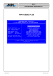
386/32 System Board Use r's Man u a I 1bis User's Guide and all accompanying software and documentation are copyrighted and all rights are reserved. 1bis product, including software and docwnentation, may not, in whole or in part, be copied, pho tocopied, translated or reduced to any electronic or machine-readable fonn without prior written consent except for copies retained by the purchaser for backup purposes. NO WARRANTY OR REPRESENTATION, EITHER EXPRESSED OR IMPLIED, IS MADE WITH RE· SPECT TO THIS DOCUMENTATION, ITS QUAUTY, PERFORMANCE, MERCHANTABILITY, OR FITNESS FOR A PARTICULAR PURPOSE. AS A RESULT, THE DOCUMENTATION IS UCENSED «AS IS", AND YOU,THE LICENSEE, ARE ASSUMING THE ENTIRE RISK AS TO THEIR QUALITY AND PERFORMANCE. ECS RESERVES THE RIGHT TO REVISE THIS USER'S GUIDE AND ALL ACCOMPANYING SOFIWARE AND DOCUMENTATION AND TO MAKE CHANGES IN THE CONTENT WITHOUT OBUGATION TO NOTIFY ANY PERSON OR ORGANIZATION OF THE REVISION OR CHANGE. IN NO EVENT WILL THE VENDOR BE LIABLE FOR DIRECT,INDIRECT, SPECIAL, INCIDENTAL, OR CONSEQUENTIAL DAMAGES ARISING OUT OF TIlE USE OR INABILITY TO USE TIllS PRODUCT OR DOCUMENTATION, EVEN IF ADVISED OF THE POSSmILITY OF SUCH DAM AGES. IN PARTICULAR, THE VENDOR SHALL NOT HAVE LIABILTI'Y FOR ANY HARDWARE, SOFIWARE, OR DATA STORED OR USED WITIl TIlE PRODUCT, INCLUDING TIlE COSTS OF REPAIRING, REPLACING, OR RECOVERING SUCH HARDWARE, SOFIWARE, OR DATA. Copyright 1988 All rights Reserved. Manual Version 1.0 XT and AT are trademarks of International Business Machines Corporation Contents Introduction ........................................................................................ 1 Board Layout ......................................................................... 3 Hardware ............................................................................................ 5 Specifications ......................................................................... 5 General ...................................................................... 5 Memory Subsystem ................................................... 10 CS8230 ChipSet ........................................................ 16 ROM BIOS ................................................................ 17 Peripheral Connections .............................................. 18 Setup ...................................................................................... 21 Jumper Switches ........................................................ 21 Before Installation Setup ........................................... 26 After Installation Setup ............................................. 28 Changing The Original Setup .................................... 30 Software ............................................................................................. 34 Specifications ......................................................................... 34 AMI BIOS Setup Program ........................................ 34 AMI BIOS Extended Setup Program ........................ 35 Setup ...................................................................................... 36 AMI BIOS ................................................................. 36 The Extended Setup Program .................................... 38 Installation & Operation .................................................................... 48 Memory Expansion Card ................................................................... 55 Care & Maintenance .......................................................................... 63 Installing Upgrades ............................................................................ 67 Checklist Your 386/32 package should contain the following: • The 386/32 mainboard • A 3.6 volt Lithium battery • This manual Important! If you do not intend to read this manual completely be certain to at least review the Operation section. The 386/32 chip set requires correct configuration information and if incorrectly setup can disfunction. This section covers what to do in such an event. It is also advisable to review the information on Software Setup. Introduction The 386/32 system board is a speed and function enhanced computer mainboard that represents a significant technological ad vance over original 80386 designs. The board design includes a vari ety of high po.wered features that place the 386/32 at the forefront of high speed '386 technology. With increased power and flexibility comes an increase in the complexity of hardware and software setup. This manual is designed to provide the basic information necessary for the end user to understand and properly use the 386/32. It also con tains the information necessary to set up more complex configurations and/or upgrade a 386/32-based system. One of the main features that distinguishes the 386/32 is the Chips & Technologies CS8230 chip set. The chip set is comprised of seven LSI (large scale integration) chips that along with C & T's Inte grated Peripherals Controller enables the user to control the relation ship between the microprocessor, the expansion bus and the on-board memory. This offers a wide degree of flexibility in configuring the board. Another important feature is the 386/32' s memory design. The board uses a memory structure called page interleaving that allows an operating speed of either 16 or 20MHz (megahertz) without requiring high speed memory chips. 1 Introduction This manual has been designed to be useful for several pur poses. If your 386/32 is already set up in a functioning system you may want to. review the manual to familiarize yourself with the fea tures of the board and where things are. This will be helpful in the un likely event that you should ever have a problem with your 386/32. For those who want to alter the board's configuration or upgrade it, the manual will serve as a guide to both procedure and specifications. While the necessary information is included in the manual, we recom mend that unless you feel confident of your ability to do the work, it would be best to have your dealer or a local service shop do it for you. If you decide to make alterations to the system yourself check to see that doing so will not violate your system warranty. If it does you may want to have the work done by an authorized dealer. Board Layout The diagram on the next page shows the layout of the 386/32 and the location of important components on the board. Introduction 10 r-l 11 I 1 2 I I I nO I m-3 I 9--l- I I,m III I I 1:::11111 11111 1111 I IJ_....I----+-_ 4 II II 8- I I I <:::>= e e e 7 I -=-=~-+-5 __ 6 386132 System Board layout 3 Introduction 386/32 Board Layout Key 1: Video mode selection jumper J3, Battery connector J2 2: Keyboard connector 3: Power supply connectors 4: Oscillator (16/20MHz) selection jumper J4 5: 80387 math coprocessor selector jumper J5 6: 80387 math coprocessor socket 7: Case connectors (Speaker, Keylock, Reset, Speed, LED) 8: SIP DRAM memory banks 9: 32-bit Memory Expansion Card slot 10: 8-bit expansion slots 11: 16-bit expansion slots Note: Multiple elements are listed left to right 386/32 system board layout key 4 Hardware Specifications The ECS-386/32 a 80386-based mainboard that can run in two different dual speed modes. It is six-layer board sized to fit in virtually any system unit case from an XTTM to tower cases. A 386/32 system will run at either eight, ten, sixteen or twenty megahertz (MHz). It can use any version of MS-DOS above version 3.xx, in addition to the OS/ 2 and Xenix/U nix operating systems. Size The 386/32 measures approximately 8.5 x 13 in (22.5 x 33 cm) and has ten mounting holes placed so that the board can be mounted in as wide a variety of cases as possible. The printed circuit board is con structed with six layers to minimize radio frequency interference. 80386 CPU The 386/32 uses an 80386 microprocessor that runs at a clock speed of either 16MHz or 20MHz. In the configuration using 100 nanosecond DRAM the processor runs at near zero wait states. The 386/32 is wait state selectable for either near zero (.7) or one-wait state and can be software switched between low and high speed modes. By using the extended setup program that is provided with the 386/32 AMI BIOS you can select the microprocessor clock speed. 5 Hardware 80387 Math Coprocessor The 386/32 has a socket for the installation of an 80387 math coprocessor. If an 80387 chip is to be installed, make certain that it is clock speed compatible with the 386/32. The 80387-16 is required for the 16MHz 80386 and an 80387-20 for the 20MHz 80386. Refer to the section on component installation for guidance regarding the in stallation of the chip if you intend to do it yourself. Remember to check and make sure that doing the work yourself will not void your warranty. Expansion Bus The 386/32 uses a modified eight slot AT style expansion bus. The bus is comprised of two 8-bit expansion slots and five 16-bit ex pansion slots and one 32-bit memory expansion slot. These will accept all the common expansion cards that conform to the standard slots. You should check to make sure that any cards added are speed com patible with the 386/32. The slots each have two parallel rows of connecting pins. When the connecting edge of an expansion card (the "golden fingers") 6 Hardware is inserted between them they grip the fingers and establish the con nection between the board and the card. It is important to keep these connectors clean and dust free so that a proper connection can be made. Look in the Care and Maintenance section for information relat ing to this. The Slots 8-bit The two eight-bit expansion slots can be used for expansion cards that do not require a sixteen-bit path for maximum function. An example of this type of card would be many video display cards. The slots are one-piece and shorter than the others. They have a total of 62 pins divided into two rows of 31 each. 16-bit The six sixteen-bit expansion slots provide a wider data trans mission pathway and will commonly be used by cards such as hard disk controllers, network cards and many I/O expansion cards. The slots are of two-piece construction with one long section and one short. The long sections are the same as the 8-bit slots. The additional short sections have 36 pins divided into two rows of 18 each. These two sections together make up a 16-bit data path. Cards that use these slots must be plugged fully into both sections of the slot. 7 Hardware The 32-bit slot The 386/32 has one specialized slot for an optional memory expansion card that uses a 32-bit data path. The slot has 80 pins di vided into two rows of 40. This slot allows the use of additional mem ory that uses a 32-bit pathway to the microprocessor rather than the 16-bit path used by standard memory cards. The 386/32 has an op tional memory card that uses this slot to add up to an additional 8MB of memory. As the pinouts are proprietary to the 386/32, only this card can be used in the slot. 8-bit slots 32-bit slot 11111 16-bit slots 386/32 Expansion Slots 8 Hardware The 32-bit Memory Expansion Card The 386/32 has an optional memory expansion card that uses the special 32-bit expansion slot mentioned above. It can be used to add either 2MB or 8MB to the main board memory subsystem without sacrificing memory access speed. The memory on the card is divided into two banks, both of which must be completely filled with the same type of memory chip in order for the card to be used. The card uses standard DIP (Dual In-line Package) DRAM chips and can use either 256Kbit or 1Mbit memory chips. If 256Kbit chips are used 2MB of memory can be added to the card, 1MB in each bank. If 1Mbit chips are used 8MB of memory can be added, 4MB in each bank. The bank numbers can be assigned as either 2 and 3, or 0 and 1. If the two banks on the card are assigned as banks 0 and 1 the memory banks on the main board can not be used at all. De tails about this and other memory related subjects are provided in the section on Memory below. Card setup information and other details are in the Memory Expansion Card section. 9 Hardware Memory This section covers types and forms of memory applicable to the 386/32 and the structure of the memory subsystem. The 386/32 can have up to eight megabytes of memory in stalled on the board. Two sizes of memory can be used for flexibility in choosing a memory structure. All of the memory on the mainboard uses a 32-bit data path to connect to the microprocessor. The 386/32 has a slot for an optional 32-bit Memory Expan sion Card which uses a different type of RAM than the main board. The slot for the card is designed to provide a 32-bit data path between the card and the microprocessor. This allows the microprocessor to access the memory on the card at the same speed as the memory on the main board itself. The other expansion slots on the board do not have this capability. The optional Memory Expansion Card can be used to add an additional 2 or 8 megabytes of extended memory to the 386/32's memory subsystem. Types Of Memory The 386/32 memory subsystem has a versatile design that al lows the use of two sizes of DRAM (Dynamic Random Access Mem ory) that can be combined in various ways. It can use the following: 10 Hardware • 256Kbit SIP (Single In-line Package) modules of four modules totals 1MB. • 1Mbit SIP modules - a full bank a full bank of four modules totals 4MB SIP modules are comprised of chips mounted in a set on a strip that plugs in as a unit. Note that there are two sizes of RAM chip; 256Kbit and 1Mbit. It is important to distinguish between bits and bytes here. The bit measurement is for individual chips, the byte measurement is for memory size. All the RAM chips function in sets of nine whether they are installed individually or are part of a module. The individual chip measurement e.g. 256Kbit, represents the total amount of memory in one set of nine chips. Nine 256Kbit chips will therefore total 256K bytes of memory and nine 1Mbit chips 1MB (megabyte). Only one size chip can be used in anyone bank. SIP modules come in two sizes depending on which size chip they use. One module can total either 256KB or 1MB. 11 Hardware Physical Organization The 386/32' s memory subsystem is divided into two sections. The sections are called banks. There are two banks on the board each with a capacity of four SIP modules. The banks are made up of eight SIP sockets numbered 1 through 8, divided in two. Each Bank has four sockets. Bank 0 is comprised of sockets 4 through 8 and Bank 1 sockets 1 through 4. The figure below shows the arrangement of the banks. BankO Bank 1 386132 memory bank organization 12 Hardware Triple-RAM The 386/32's Triple-RAM feature uses three different types of socket in the memory subsystem. This allows the installation of up to two types and two sizes of RAM in the same system. Banks 0 and 1 are standard SIP sockets that will accept modules with either 256Kbit or 1Mbit chips. Banks 2 and 3 on the optional memory expansion card have a dual socket design that can use either 16-pin (256Kbit) or 18-pin (lMbit) DIP DRAM chips. The result is a high degree of flexi bility in installing the amount and type of memory desired. There are a number of possible configurations. The charts below detail the pos sible choices. Two Banks Installed DRAM Type BankO Bank1 Bank2 0 0 0 256Kb 0 0 1Mb 0 0 256Kb 256Kb 0 1Mb 1Mb 0 Total Bank3 Memory disabled 0 1MB 0 4MB 0 2MB 0 8MB 0 Page Interleave no no no yes yes 13 Hardware Four Banks Installed DRAM Type BankO Bankl Bank2 Bank3 256Kb 256Kb 256Kb 256Kb 1Mb 1Mb 256Kb 256Kb 1Mb 1Mb 1Mb 1Mb Total Memory 4MB 10MB 16MB When installing or adding memory the Banks must be filled in order from Bank 0 (sockets #4-8) up. Each Bank can contain only one kind of chip. Different types of chips can not be mixed in the same Bank and a bank must be completely full to function properly. Bank 0 must have a minimum of 1MB. A key aspect of the Triple-RAM feature is that the Bank num bers can be reassigned so that DIP RAM Banks can be used first. Nor mally the SIP modules are assigned the 0 and 1 positions. If you want to use DIP RAM Banks as banks 0 and 1 the bank numbering can be changed by altering a DIP switch setting on the optional memory ex pansion card. If this is done the two banks on the 386/32 main board cannot be used at all. The procedure used to set the board up this way is explained in the Memory Card Setup section below. 14 Hardware Page/Interleave Memory Memory access for the 386/32 is based on what is called a page/inter leave arrangement. This means information stored in the memory sub system is divided up, some of it going to one bank and some to an other. This allows faster memory access but requires that banks oper ate in pairs, hence the physical organization of the memory subsystem. In order to use the interleave option two banks must be filled. Use of the Interleave feature will maximize the performance of any 386/32 based system without requiring high-speed RAM chips. Wait States In order to operate at 16MHz in the page interleave mode with near zero wait states the 386/32 must have at least lOOns (nanosecond) memory chips installed. Slower chips will require the system to oper ate at one wait state. If one wait state operation is desired, 120 nanos econd memory can be used. 15 Hardware Shadow RAM It is possible to use a feature of the 386/32' s chip set called "Shadow RAM". This feature allows the relocation of the contents of the ROM BIOS to a memory location in RAM above 640K. This fea ture increases overall system speed. Use of the Shadow Ram feature is optional if only 1MB of memory installed. If this feature is not used the area above 640K in the first megabyte of memory cannot be used for anything else. Turning on the Shadow RAM feature is done by using a section of the extended setup program described in Soft ware Setup. The CS8230 Chip Set The CS8230 AT/386 ChipSet™ from Chips and Technologies allows the programming of many system board functions. The set is comprised of seven VLSI (Very Large Scale Integration) chips that enable the CPU and AT bus clock rates to be programmed as well as the Memory and I/O wait states and delays. The DRAM type, Shadow RAM capability, and DMA wait states can also be programmed. The set contains 114 bytes of CMOS RAM for storage of the additional configuration information created by the Extended Setup program of the AMI BIOS. Hardware The chip set consists of the 82C301 CPU/bus controller, the 82C302 page/interleave memory controller, the 82A303 high address buffers and 82A304 low address buffers, the 82A305 Data Bus Inter faces and the 82A306 Control Signal Buffer. The 386/32 also uses the C&T 82C206 Integrated Peripherals Controller (IPC) as an adjunct to the CS8230 chip set. It contains the CMOS RAM memory that is used to store the chip set configuration information created by the extended setup program. This information must be maintained by an auxiliary battery or it is lost when the sys tem is turned off. Information about the battery backup for the CMOS RAM is in the Hardware Setup section. ROM BIOS All microcomputer systems use a Basic Input Output System. This is software that has been permanently recorded in a ROM (Read Only Memory) chip and functions as the basic point of communica tion between the system board and the rest of the computer. The 386/ 32 currently uses the AMI BIOS from American Megatrends Inc. The Shadow RAM feature mentioned previously takes the information in the BIOS chips and places a copy of it in the computer's RAM. This speeds up operation of the system because the microprocessor can ac cess the information more quickly. 17 Hardware AMI BIOS The AMI BIOS, in addition to the BIOS program itself, con tains two setup programs that are called up when the system boots up. These are called Setup and Extended Setup. The Setup program rec ords the basic information about the hardware configuration of your system. The 386 Extended Setup is a program included to enable the programming of the C&T chip set. The possibility exists that you might lock yourself out of your system if the wrong configuration is entered. The Software Setup and Care & Maintenance sections explain what to do if this happens. The use of these programs is explained in the Software Setup section. Peripheral Connections Keyboard The 386/32 has a standard keyboard connection port at the rear of the board. The jack from the keyboard plugs into the port once the board has been installed in the case. 18 Hardware Power Supply The 386/32 requires a power supply of at least 180 watts in or der to be used in a fully configured system that includes a hard disk drive and has or may at some point have more than a minimum of ex pansion cards installed. The power supply must be of the type that has a "power good" signal. The power supply commonly supplied for AT type system boards has this feature. If you are purchasing a unit your self, ask the dealer for advice if you are in doubt as to the correct choice. Case Connections The 386/32 has on-board connectors for several features that are commonly mounted on the front panel or in many system cases. These include: • A Reset button connector • A Keylock connector • A speed selection button connector • A "Turbo" speed LED indicator connector • A speaker connector Information on how to connect these functions to the 386/32 can be found in the Hardware Setup section. 19 Hardware Battery Connector The 386/32 does not have an onboard battery to maintain the system configuration information in the CMOS RAM. To maintain the configuration information about your system hardware and chip set settings a battery pack must be used. A pack of four"AA" batteries or a battery especially designed for this purpose must be attached to the battery connector on the board. Either of these items may be pur chased separately from most computer dealers or computer supply stores. The pack or battery will have wire leads to connect it to the battery connector on the board. Instructions on how to connect the bat tery pack to the board are given in the next section. For what to do in the event that a battery-related problem arises with the configuration information stored in the CMOS RAM see the Software section. 20 Hardware Setup This section is for setting up the 386/32 before installing it in a system case. If your 386/32 is already installed in a system this section can be ignored unless a change in the system configuration is needs to be made. Jumper Switches The 386/32 has several jumper switches that must be set to de fine part of both the board and system configurations. These switches are three pin components on the board. They are turned on and off by placing or removing a cover cap over the pins. To turn a switch setting "on" one places a cap over two pins. This is called 'shorting' the jumper. All the jumpers must be set to one of two possible settings. The location of the jumpers is noted on the Board Layout dia gram at the beginning of the manual. Their functions and settings are noted below. The three jumpers on the 386/32 are for setting the moni tor type, CPU oscillator and 80387 selection. 21 Hardware 387 ON OFF (l) 1 »--I --I J5 ' I\) () o JJ 16M s: oZtu '- 20M 1 J4 386/32 jumper switches and battery connector 22 Hardware The Default Setup The 386/32 comes with the jumpers preset. The factory set tings are noted below. Monitor Setting Jumper 13 controls the video mode setting. The factory setting is for monochrome mode. Monochrome mode is turned on by shorting pins 1 and 2 of the jumper. The figure below illustrates the position. () o:IJ s: o z 386/32 video mode factory setting 23 Hardware CPU Oscillator Jumper J4 controls which of the two oscillators on the board will be used by the microprocessor. The setting is based on the speed of the microprocessor. The jumper is used to switch between the two oscillators. One oscillator is for a 16MHz microprocessor and the other for 20MHz. The 386/32 comes set for whichever microprocessor has been installed. The factory setting shorts pins 1 and 2. If a 20MHz microprocessor has been installed or if you wish to install one this jumper must be reset accordingly to pins 2 and 3. The figure below shows the two settings. 16M 20M 1 J4 16M 20M 1 J4 386132 CPU oscillator settings 24 Hardware 80387 Selection Jumper J5 is used to turn the connection to an 80387 math coprocessor chip on and off. If an 80387 chip is installed the jumper must be set to pins 1 and 2. This turns the switch "on". If no chip is installed or for some reason you do not wish to use the coprocessor the jumper should be set to pins 2 and 3. This setting turns the switch "off'. The factory setting is "off'. The figure below shows the two possible positions. 387 ON OFF 387 ON OFF 1 1 J5 J5 386132 80387 selection settings 25 Hardware Before Installation Before installing the 386/32 there may be some adjustments to make on the board. Check to see that the monitor type, oscillator and math chip jumpers are correctly set. Refer to the section above on fac tory settings if there is any doubt as to the correct setting for your sys tem configuration. Memory Banks The figure on page 12 in the Hardware Specifications section illustrates the layout of the memory subsystem on the 386/32 board. The 386/32 onboard memory subsystem has eight sockets that use SIP RAM modules. Detailed information about this is located un der Specifications in the Hardware section. Tbeoptional 32-bit mem ory card has another two banks with dual sockets. Setup of these are explained in the Memory Card section. 26 Hardware Several configurations are possible when setting up the mem ory subsystem. The main necessity is that the memory banks be filled in pairs if the page interleave function will be used. Since the 386/32 was designed to make use of this feature to obtain maximum perform ance page interleaving should be used unless there is some specific reason not to do so. Any two banks must also have the same type of chips installed, e.g. all IMbit or all 256Kbit. The 386/32 can use up to four memory banks. The banks are numbered 0, 1,2 and 3. Banks 0 and 1 are on the board. Banks 2 and 3 are on the memory expansion card if one has been installed. There are several possible bank configurations some of which use the SIP sock ets only and others that use the SIP sockets and the two banks on the memory card. There are a number of possible memory configurations as noted below. 1) 2) 3) 4) 5) 6) 7) DRAM Type BankO Bankl Bank2 Bank3 256Kb 0 0 0 1Mb 0 0 0 256Kb 256Kb 0 0 256Kb 256Kb 256Kb 256Kb 1Mb 1Mb 0 0 1Mb 1Mb 256Kb 256Kb 1Mb 1Mb 1Mb 1Mb Total Memory 1MB 4MB 2MB 4MB 8MB 10MB 16MB 27 Hardware Some of the above configurations assume four banks in opera tion. If four banks are used the memory expansion card must be setup to reflect the amount of memory installed on the card. If the card will be set up as Banks 0 and 1 the onboard memory can not be used and only two banks will be available. The setup procedure for the memory expansion card is explained in the Memory Card section. After Board Installation Setup After the 386/32 has been installed in a system case there are some additional connections that may be made to the board, The In stallation section contains a brief description of how to install the 386/ 32 system board in a case. Case Connections There are five connectors on the 386/32 that can be attached to indicators or devices on a system case if they are present. They are: • Keylock connector • Speaker connector • Reset Button connector • Processing Speed Switch connector • Processing Speed LED connector 28 Hardware J6 J7 1 J9 SPEED RESET SPEAKER J8 KEYLOCK LED 1 386132 case connectors These connectors look the same as jumper switches and have varying numbers of pins. Whichever indicators or devices are present on the case will have wire leads extending from them with plastic fe male connectors attached. The connectors should be plugged onto the appropriate connecting pins on the board. The sets of connecting pins are clearly labeled. If the lead requires a specific orientation when it is plugged on, the pin 1 wire will generally be separated from the other wires by a space. You should then orient the connector so that this wire plugs onto pin 1 of the connecting pins on the board. The pin I position is clearly marked beside the speaker and keylock connectors. 29 Hardware Power Supply The power supply connector on the 386/32 is made up of two six-pin male components in a line. Dual connectors from the power supply plug directly onto the connectors at the right rear of the board. The two female connectors from the power supply must be attached in the correct order. They can only plug on in one way but the correct order is essential. Each has multiple wires extending from it. The black wires on each connector should be placed so that they are to the inside. Keyboard The 386/32 has a standard female five-pin DIN keyboard con nector located at the right rear of the board as noted in the board dia gram. The connecting jack from the keyboard plugs directly into it once the board has been installed in the system unit case. If You Change Monitors * Monochrome: Short pins 2 & 3 Color: Short pins 1 & 2 30 Hardware If you change from a monochrome to a color monitor or vice versa after the 386/32 has been installed you must change the video mode setting on the board. To do this pull the jumper cap off and re place it according to need. Pins 2 and 3 are for monochrome, pins 1 and 2 for color. () o :D s: o z () ....... o :D s: o z 386/32 video mode settings 31 Hardware Connecting The Battery Source The 386/32 requires an external battery source to maintain the configuration information recorded in the CMOS RAM on the board. In setting up the 386/32 a battery pack or special battery designed for this purpose must be attached to the board at the battery connector. Once this battery backup has been installed, the configuration infor mation recorded in the CMOS RAM on the board can be maintained when the system is turned off. If the battery power source is not at tached it will be necessary to reenter the configuration information ev ery time the system is turned on. Battery packs that use commonly available batteries and batteries especially designed for this purpose are available from most computer dealers and computer supply stores. When the battery wears out it should be replaced. As mentioned, the 386/32 comes with a 3.6 volt high energy non-rechargeable lithium battery. This battery should give an extended period of use but will eventually wear out and need to be replaced. The battery comes with a two-piece hook and loop closure attachment pad. One part of the pad can be detached and once the cover strip of its adhesive backing has been removed, can be attached to the case or power supply. The battery can then be attached to this using the hook and loop closure. 32 Hardware *Attach the battery to the battery connector 12. The Pin 1 wire of the connector is separated from the other wire lead by a space. If you look at the underside of the connector you will see that one pin socket is blocked. This space corresponds to the missing pin of the 12 connector on the 386/32. Orient the battery con nector correctly and plug it onto the board. The figure below indicates the Pin 1 position. 386/32 battery connector, pin 1 indicated 33 Software Specifications AMI BIOS Setup Programs The AMI BIOS firmware contains two hardware setup pro grams. One is for recording your system configuration and the other is for the chip set. They can be run after the system has been turned on and the memory test is finished or has been escaped. On screen mes sages clearly explain what to do and how to use the first program.. The second program also has instructions but is more complex to use. The Setup Program The hardware setup program records information about the structure of your system. It asks you to enter the time, date and infor mation about peripherals attached to the 386/32. This includes display type and disk drive types. The program prompts for the information it requires and its use is self-evident. 34 Software The Extended Setup Program The second setup program in the AMI BIOS is an extension used to program the 386/32's chip set. This program is comprised of two sections. Most of the information required can be entered in the fIrst part. There is some information which must be entered in the somewhat more complicated second section. The Software Setup sec tion explains how to use the extended setup program. It is used to rec ord information about the memory size, speed, type and configuration. It is important to follow the instructions given in the Software Setup section. Incorrect entry of information or experimentation when using the program can result in locking your self out of the system. If this happens you will need to clear the CMOS memory on the board and in the chip set and reenter the configuration information. The Op eration section contains information on what to do in such an event. 35 Software Software Setup Software setup of the 386/32 takes place after all hardware setup has been completed. You should at that time make a specific record of what the configuration is and keep it for reference. The in formation is needed to use the two programs explained in this section. AMI BIOS The Setup Program The AMI BIOS setup program mentioned previously is used for recording the basic system hardware setup. If your 386/32 is al ready installed in a working system you will not need to use this pro gram unless the configuration already recorded in the on-board CMOS RAM is lost or a change is made in your system hardware configura tion. If the information is lost due to loss of battery power you will need to reenter the configuration. If the configuration is altered the changes must be recorded. 36 Software Follow the instructions as they come up on the screen to com plete the procedure. The initial prompt on the screen tells you to press the <Del> key if you want to use the setup program. It is displayed briefly just after the RAM test is run when you fIrst turn on the sys tem. If it disappears before you have a chance to respond turn the sys tem off and on again and the message will reappear. The initial screen prompt is: Press <DEL> key to run SETUP/EXTD-SET Press the <DEL> key on the numeric pad to enter the program sequence. A second message will appear asking Yes/No if you want to enter one of the programs. If Yes, type Y and press the Return key. Another message will appear asking which of the two programs you want to run. It will give you a 1/2 choice. Choose 1 for the SETUP program and press the Return key. If No (you don't want to enter ei ther of the setup programs), type N, press the Return key and the ma chine will exit the sequence. 37 Software The Extended Setup Program (ESP) The ESP is designed to provide a relatively easy way to reeord setup configurations for the 386/32 chip set. The program has five sec tions three of which are for entering infonnation and two which con trol the recording of that infonnation. The main purpose of the ESP is to record memory related infonnation. The other programmable fea tures of the 386/32 chip set are not intended to be user modified. If your system is already set up you will not need to use the ESP unless you want to make a change in your system hardware con figuration. How To Use The ESP The ESP interface is divided into sections each with a separate function. The program is structured as a heirarchy with successive lev els within each section. Movement between or within different sec tions of the program is accomplished using the arrow and PgUp, PgDn keys. Their use is explained on-screen. The <Enter> ( or <Return» key is used to move between levels of the program and to select set tings. The <Esc> key lets you abort settings andlor retreat to higher levels of the program. 38 Software The ESP has on-screen instructions on how to use the pro gram. The following is a brief explanation of each section's function. Each section can be opened by highlighting its title and then pressing the <Enter> key. When using the program go through the sections se quentially. 1. EASY C&T CHIPSET REGISTER SETUP Opening this section first displays a warning about incorrect configuration entry as mentioned previously. Press the <Enter> key to continue. A menu screen will then appear that displays configuration information. Some of the options displayed are fixed. some you will set while this menu is open and others are set in the other sections of the ESP. The figure on the next page shows what the menu screen looks like with of some example values entered. 39 Software C&T 386 EXTENDED SETUP PROGRAM Ver-l.10, (C)1988,American Megatrends Inc. Bank o 1 2 3 Memory Configuration Enable/Disable DRAM Type Waitstate ENABLED ENABLED DISABLED DISABLED o o o o Processor Clock PROCESSOR OSCILLATOR 256K 256K Clock Source Bus Clock PROC CLOCK/2 DISABLED DISABLED STATE STATE STATE STATE DMA Clock SCLK/2 Shadow Ram/Interleave Video Shadow Interleave BIOS Shadow FOOOOH,64K COOOOH,16K C4000H,16K ENABLED WAIT WAIT WAIT WAIT ZERO WAIT STATE ONE WAIT STATE MOVE BAR-<PgUp/PgDn> CHANGE WINDOWS -+4++ EXIT-<ESC> ENABLED 386132 Extended Setup Program, Easy Setup section There are three sections in this menu screen: • Memory Configuration • Clock Source • Shadow RAM/lnterleave The box in the lower right comer of the screen is used to move around the menu and make entry selections. Either the PgUp or PgDn key can be used to switch back and forth between the options dis played. The arrow keys allow you to move between the different op tions. Each section is explained below. 40 Software Memory Configuration This is used to set the wait states for the memory subsystem. Set this option as follows: • 0 wait states if your system memory is lOOns or faster • 1 wait state if your system memory. is slower than lOOns The other information in the Memory Configuration section is set in the Advanced Register Setup section of the ESP. Clock Source The information in this section is set when your system is as sembled. It is not user adjustable. Do not make any changes in this section! Shadow RAM\lnterleave This section allows you to use the Shadow RAM feature to speed up your system. Not all video cards can support the option to place the video BIOS in RAM. You will need to check or experiment to see if your video adapter can use this feature. 41 Software If you have more than one bank of memory installed on the 386/32 you should enable (turn on) the Interleave feature in this sec tion unless there is some special reason not to do so. Once you have made the necessary entries in this section press the <Esc> key to return to the top level of the program and go on to the next section. As long as you have not exited the ESP entirely you can always come back and make changes if you discover you've made an error. 2. ADVANCED C&T CHIPSET REGISTER SETUP Opening this section first displays a warning about incorrect configuration entry as mentioned previously. Press the <Enter> key to continue. A tri-part menu screen will appear as shown in the figure on the next page. 42 Software C&T 386 EXTENDED SETUP PROGRAM Ver-1.10, (C)1988,American Megatrends Inc. 82C206 01H -> BITS 7-0 11 00 00 82C301 04H -> 05H -> 06H -> RRR 0 o a 00 00 01 10 10 01 82C302 08H 09H OAH OBH OCH ODH OEH OFH 10H llH 12H 13H 28H 2AH ;. 0 - Go to Prev/Next Register Go to Prev/Next Entry Scroll Bit value - PgUp/PgDn Return to MAIN MENU - <ESC> 0 RR 01 01 BANK 0/1 TYPE/START ADDRESS -> -> -> -> -> -> -> -> -> -> -> -> -> -> RRR 0 o0 0 a 0 0 0 a 0 a 0 0 0 0 0 0 1 1 1 1 1 1 01 1 1 00 1 1 0 RRRRRRR 0 0 1 1 0 0 O· 0 a a a a 0 a 0 0 0 0 0 0 1 1 1 1 1 1 1 1 1 000000 RRRRRR 111111 RRRRRR RRRRRRR 1 Bank 011 DRAM TYPE OO=BANK DISABLED 01=256K DRAMS 10=lMEG DRAMS ll=RESERVED 386132 Advanced Extended Setup screen 43 Software There are two boxes on the right. The top one gives instruc tions on how to move about in the menu which are much the same as the previous section. The box below displays the option selected from the large box at right and notes how to set that option to the desired position. Although this all looks rather complicated you actually only need to make two settings in this section. These are to enable the RAM banks that will be used and note what type of memory has been installed. To accomplish this use the arrow keys to move about the menu screen and do the following. * Enable Bank 0/1 at lOH At least one bank must be enabled for your system to function no matter whether it is on the main board or the optional 386/32 mem ory card. To do this use the arrow keys to highlight the two-digits after the lOH ->. The box at right will display the following: BANK 011 TYPEISTART ADDRESS BANK all DRAM TYPE OO~BANK DISABLED 01~256K DRAMS 10~lMEG DRAMS ll~RESERVED 386/32 RAM Bank setup 44 Software Choose the appropriate setting depending on which type of DRAM is installed in Banks 0 and/or 1, either 256K or 1M bit. Use the PgUp or PgDn key to make the selection. - 01= 256K -10 = 1MEG Do not set the other five digit part of the lOH register. Once you have made the setting above continue and: * Enable Bank 2/3 at 12H If four banks of memory are installed in you system you will need to enable Bannks 2 and 3. The procedure is the same as for Banks 1 and 2. Use the arrow keys to highlight the two-digits after the 12H ->. The box at right will display the following: BANK 2/3 TYPE/START ADDRESS BANK 2/3 DRAM TYPE OO=BANK DISABLED Ol=256K DRAMS lO=lMEG DRAMS l1=RESERVED 386132 RAM Bank setup 45 Software Choose the appropriate setting depending on which type of DRAM is installed in Banks 2 and 3, either 256K or 1M bit. If the banks are not used they must be diabled. Use the PgUp or PgDn key to make the selection. - 00 =BANK DISABLED - 01= 256K -10= lMEG Do not set the other five digit part of the 12H register. When you have made the setting you have completed what you need to do in this section. Press the <Esc> key to return to the Main Menu of the program and go on to the next section. As long as you have not exited the ESP entirely you can always come back and make changes if you discover you've made an error. 3. ENABLEIDISABLE VIDEO AND MAIN BIOS SHADOW You should use the first section of the ESP to perform this function. This section is not necessary for the end user to make selec tions from this menu. 46 Software 4. WRITE CMOS REGISTERS AND EXIT If you select this and press the <Enter> key the values entered will be recorded in the extended CMOS memory of the 386/32 chip set. The 386/32 will then check this every time you turn your system to find out the extended setup information. 5. DO NOT WRITE CMOS REGISTERS AND EXIT Selecting this option and pressing the <Enter> key lets you exit the ESP without recording any new values or changing old ones. If you want to save a new configuration do not use Exit to get out of the ESP. If you do the setting information will be lost. Having made whatever entries were necessary in the two setup programs above you can now proceed to use your 386/32-based sys tem without further reference to these programs until such time as you make a change in the system hardware configuration or the system configuration information stored in CMOS RAM is lost and must be reentered. 47 Installation & Operation Installation If your 386/32 is not installed in a computer system then the following basic information 'will be of use. Due to the wide variety of cases the 386/32 can be installed in it is not possible to provide exact instructions for every case. This section covers the factors common to installing the board in most situations. The 386/32 has mounting holes that accommodate the standard mounting points for tfie IBM PCIXT, PC/AT and compatible cases. Most cases use these configurations or some compatible variation of them. Before removing the board from its anti-static bag read the sec tion below on static electricity precautions. Static Precautions Static electricity is a constant danger to computer systems. The charge that can build up in your body may be more than sufficient to damage integrated circuits on the system board. It is therefore impor tant to observe basic precautions whenever you are going to handle or use computer components. Although areas with a humid climate are much less prone to static build-up, it is best to always safeguard against accidental damage that may result in expensive repairs. The following measures should generally be sufficient to protect your equipment from static discharge: 48 Installation & Operation • Discharge any static electric charge that may have built-up in your body by touching a grounded (earthed) or anti-static surface. Commonly available anti-static pads are one example. If nothing else, touch the silver expansion slot covers at the left rear of the system unit case and after having opened the case, the power supply. This assumes that the system unit is plugged in, thus grounding the case. Be certain to do this before removing components from their protective anti static covering. • When handling individual cards, boards or modules, be care ful to avoid contact with the components on them wherever possible and also with the "golden finger" connectors that plug into the expan sion bus. It is best to handle system components either by their edges or by the mounting bracket that attaches to the slot opening in the case. In following the above recommendations it is not necessary to be ex cessively cautious. The idea is just to take reasonable care. Always make certain that everything that connects to the sys tem case, including the power supply is unplugged before doing the installation work. 49 Installation & Operation Mounting Holes The 386/32 has ten mounting holes drilled in the printed circuit board. These will line up with some or all of the mounting points on your case. Some form of mounting hardware is used to fasten the board to the case. In some cases the long inside edge of the board fits under metal flanges in the case frame rather than being screwed to the case. Mounting Fasteners Cases can come with a variety of mounting fasteners, some made of metal and some of plastic. In general the metal type will screw into the case and then have another piece that screws the board to the fastener. Plastic mounting fasteners are usually some kind of pressure fitting that sn/itps into the case and then into the board. One case may have both types, the metal fasteners serving to ground the board to the case. 50 Installation & Operation Operation General When a 386/32 system first boots up several messages will ap pear on the screen before the system software is accessed. These are generated by the BIOS and the 386/32 software. They include: • RAM test • BIOS SetuplExtended Setup program message These messages include instructions on their use where appli cable and other information. The Setup programs are discussed in the Software section. The Keyboard Lock The 386/32 has a connector for a keyboard lock. If this has been connected to the from panel of your case, a key provided with the case can be used to electrically disconnect the keyboard from the board. This does not actually lock the keyboard. The keyboard cannot be turned back on from this switch without the correct key. This de vice provides security from casual tampering with your system. It will not stop a determined intruder if your case can be opened and the function disconnected from inside. 51 Installation & Operation Reset Switch The 386/32 has a connector for a Reset button. If this has been connected to the front panel of your system case the button can be used to restart your system without turning the power off. Pushing the button will cause your system to restart from the memory test. It is then necessary to reboot your operating system software before you can continue. Changing Processing Speed Hardware Switch The 386/32 has a connector for a hardware processor speed switch. If this has been connected to the front panel of your system you can use it to switch between the maximum processing speed (of ten referred to as "Turbo") and the secondary slower processing speed. Pushing the switch on the panel changes the speed. If the higher speed is in use and your front panel has the appropriate indicator light, the LED indicator will light up while the high-speed mode is in use. 52 Installation & Operation Keyboard Switch The processing speed can also be changed using a keyboard command sequence. To use this feature do the following: • Hold down the <Ctrl> and <Alt> keys simultaneously and press: a + (plus) for the high speed, or a - (minus) for the low speed In practice you will probably always want to use the high speed mode unless you encounter software compatibility problems. These might occur with some older software that is speed dependant and must run at the lower speed. This is a common concern of dual high-speed mainboards. 53 Installation & Operation Clearing The CMOS RAM If incorrect setup values are recorded using the extended setup program it is possible the 386/32 will "hang", i.e. the screen image will freeze and the system will not function even if you turn it off and on again. If this happens you must use the following procedure to rec tify the problem. This procedure clears the incorrect information stored in the CMOS RAM and allows you to reenter the correct infor mation. * To clear the CMOS RAM do the following: • Tum the system off (power off) • Press the <INS> key and tum the system back on (power on). Hold down the <INS> key until the screen display appears and then release it. Having done this to clear the CMOS RAM you must now reenter correct configuration values using the extended setup program as described in the Software Setup section. 54 Memory Expansion Card Card Specifications The 386/32 memory expansion card is an option that allows the 386/32 to use an additional 2 or 8MB of extended memory. The card uses standard DIP DRAM chips that are individually installed. Either 256Kbit or IMbit DRAM chips can be used. The card is di vided into two banks. If both banks are used they must be filled with the same size chips because of the page interleave memory manage ment used by the chip set. If only one bank is used it must of course contain only one type of chip. A number of different memory configurations can be setup. A DIP switch on the card is used to identify the configuration used so that the CPU will know how much and what type of memory is in stalled on the card. The settings vary according to the configuration. Detailed information about this is given later in this section. 55 Memory Expansion Card Card Layout The figure below notes the arrangement and position of the various components on the memory expansion card. Memory Banks Bank 1 or 3 Bank 0 or 2 I I DIP switch 386132 Memory Expansion Card layout 56 Memory Expansion Card Memory Types The 386/32 Memory Card can use either 256Kbit or IMbit DIP RAM chips. These are the common type of RAM chips that are installed individually as opposed to the SIP multichip modules used on the 386/32 mainboard. As with all memory chips a certain mini mum must be installed as a set. Each set of nine chips will provide 256K bytes or 1 megabyte of memory depending on the size of chip used. The Memory Card has two banks that must each be filled com pletely for the bank to function. In pra.ctice this means that each bank will require a total of thirty-six chips to fill a bank. The chart below shows various possible configurations for the card. No. of Banks Chip Type 1 1 2 2 256Kbit 1Mbit 256Kbit IMbit Total Memory No. of Chips 1MB 4MB 2MB 8MB 36 36 72 72 57 Memory Expansion Card Memory Organization The 386/32 uses a dual socket design to allow the installation of either 256Kbit or IMbit memory chips. The sockets are grouped in banks. The figure below shows the design of an individual socket with important features indicated. Notched End I •• •• •• •• •• •• •• •• •• •• •• •• •• •• •• •• •• I 1Mbit Socket •• •••• • ••• •••• •••• •••• • ••• • ••• • ••• 256Kbit Socket 386132 Memory Card dual socket DIP RAM sockets 5R Memory Expansion Card· The individual sockets are grouped in rows to form the Banks. Each row has six sockets and six rows form one bank. Each set of nine chips therefore will occupy one and a half rows and each Bank con tains four sets of chips for a total of thirty-six chips. When fully popu lated the 386/32 memory card will have seventy two chips installed. As mentioned previously the entire card must be filled in order for it to be used in the page interleave mode. The Memory Card can use one Bank only if no interleave is set and the memory banks on the 386/32 board are disabled. Card Setup The DIP Switch Once the amount of memory to be installed on the card has been decided the DIP switch on the card must be set to indicate the to tal amount of memory that will be present. The DIP switch is com prised of eight individual switches each of which must be set either ON or OFF. The ON position is clearly noted on the switch. The fol lowing figures indicate the setting required for each memory option. Set the DIP switch so that it duplicates the setting shown for total amount of memory you have on the Memory Card. 59 Memory Expansion Card MemoryC8rd 386/32 Total ON ~DDD~DDD 36 x 256Kbit none 1MB 36x1Mbit none 4MB 72 x 256Kbit none 2MB 72 x 1Mbit none 8MB 72 x 256Kbit 8 x 256Kbit 4MB 72 x 256Kbit 8 x 1Mbit 10MB 72 x 1Mbit 8 x 1Mbit 16MB 1 2 345 6 7 8 ON ~DDD~DDD 1 2 345 6 7 8 ON ~D~D~D~D 1 234 5 6 7 8 ON ~'D~D~D~D 1 2 345 678 ON D~D~D~D~ 1 2 345 6 7 8 ON D~D~D~D~ 1 2 3 4 5 678 ON D~D~D~D~ 1 2 3 4 5 678 386132 Memory Expansion Card DIP switch settings 60 Memory Expansion Card Setting The DIP Switch Setting the DIP switch on the 386/32 Memory Card can be done using either the fingers or a pointed object. The eight individual switches should be set for the amount of memory to be installed on the card according to the figures above. Make certain the switches are in the proper position as shown in the switch illustration for that amount of memory. Memory Installation The Installing Upgrades section explains how to install mem ory chips on the Memory Expansion Card. It is essential that you do not install 256K bit memory on the mainboard and 1M bit memory on the expansion card. The expansion card can only have 1M bit mem ory chips installed if the 386/32 on-board memory is also 1M bit or if the 386/32 on-board memory subsystem is not being used. 61 Memory Expansion Card 386/32 Memory Card Installation If your system does not currently include the 386/32 Memory Expansion Card you can have your dealer install one for you. If you want to install the card yourself be certain that doing the work will not void your system warranty. To install the optional 386/32 memory expansion Card follow the instructions in your system manual for installing expansion (add on) cards. The only difference between insialling common expansion cards and the 386/32 card is that the slot for the memory card is of a different size than the rest of the slQts. This has no influence on the in stallation procedure. As always when doing any kind of work on your computer system, be certain to take appropriate precautions against static electric damage to the system as mentioned elsewhere in this manual. 62 Care & Maintenance Occasional Cleaning Computer systems are sensitive to dust and dirt and can be come contaminated over time. Most computer users are familiar with the need to clean and maintain floppy disk drives. Your 386/32 is much less sensitive to contamination but it is nevertheless a good idea to examine the board and the devices connected to it once or twice a year and clean them if necessary. How often this is necessary will of course depend on how clean your computing environment is. It is best to avoid placing your computer in conditions where it will become contaminated. Cleaning can generally be limited to a thorough vacuuming. Do not attempt to open your system if it will void the warranty. If you will do the work yourself rather than taking the system to a dealer or service center, do the following: • Turn off and disconnect all connections to the system • Observe static precautions as mentioned in the Installa tion section. • Open the case according the directions in your system manual. Care & Maintenance • Examine the interior for obvious irregularities. If some thing does not look right stop. Close the system and take it to a dealer or service center. If there is no evidence of a problem continue. • Use a miniature vacuum designed for cleaning this type of equipment to thoroughly clean the interior. Be careful not to loosen or disconnect anything. When finished check that all connections are intact then close the case and reat tach the peripheral connections. It is also a good idea to use a dust cover to prevent the interior of the computer from developing excessive deposits of dust inside. The keyboard should be similarly protected. Taking such precautions in advance will help reduce the frequency with which your system will require maintenance. Care & Maintenance Replacing The External Battery The batteries in the battery pack or the special battery that the 386/32 uses to maintain the configuration information in the on-board CMOS memory will eventually require replacement. This can be done by your dealer or any qualified service personnel. If you want to re place the battery(ies) yourself, remember to make certain that opening your system case will not void the warranty on your system. The life of the batteries may very well extend beyond the term of warranty. To replace the batteries do as follows: • Open your system CPU case according to the instruction in the system manual. Always remember to take precau tions against static electric damage and see that all electri cal devices are disconnected from the CPU and unplugged from their power source. • Unplug the battery connector lead from the 386/32 board. • If your system uses a multiple battery pack, remove the exhausted batteries and replace them with new ones of the same specification. If your system uses a single battery de signed for use in a computer, replace it with a new battery of the same specifications. 65 Care & Maintenance • Attach the wire lea.d from the battery pack or battery to the battery connector on the 386/32 board. Remember to orient the connector properly such that the Pin 1 wire con nects to Pin 1 of the battery connection on the board. The Pin 1 wire should be separated from the other wires or marked. Pin 1 of the battery connector on the 386/32 is marked on the board. When you have completed replacing the battery supply for the CMOS RAM close your CPU case and reassemble your system ac cording to the directions in your system manual. Once you have done this you will need to reenter the configuration information for your system using the Setup programs described in the Software section. Using the battery will preserve the setup information in the CMOS memory. If you don't preserve the information in this way it will be necessary to reenter all configuration data every time the sys tem is used. 66 Installing Upgrades This section deals with ways in which you might want to up grade the 386/32 mainboard. There are two ways in which the board that can be upgraded. One is to add memory and the other is the addi tion of a math coprocessor chip. Memory Upgrades You may at some point want to change the original configura tion of your 386/32 by adding memory. There are a variety of ways to configure the 386/32' s memory subsystem. As mentioned previously the 386/32 can use three different forms of DRAM chip. This section gives general guidelines on the installation of RAM chips. It does not explain how to configure the memory bank arrangement or other memory related subjects covered elsewhere in the manual. Installing Memory Chips There are several points to remember when installing memory chips. As mentioned previously, do not attempt to modify the 386/32 if it is already installed in a system and doing the work yourself will void your system warranty. These instructions assume a degree of technical knowledge and competence and will not cover in detail any thing other than the information related to chip installation. Seek tech nically competent help if necessary or have the work done by your dealer or local computer service center. When installing chips be cer tain to do as follows. 67 Installing Upgrades • Always observe static electricity precautions as men tioned earlier in the manual. • Choose your new memory configuration carefully before purchasing new chips. A memory upgrade should be based on your needs and a careful review of the memory con figuration information in this manual. Be careful to accu rately specify the correct chip type. The figure below shows the different types of memory that can be used in on the 386/32. 1Mbit DIP RAM 256Kbit DIP RAM ... SIP module (256Kbit or 1Mbit) 386/32 RAM chip types 68 Installing Upgrades Installing SIP Modules The 386/32 has eight sockets for SIP modules. These are di vided into two banks of four each. Each bank must be completely full in order to operate so you need a minimum of four modules and eight to use the interleave feature. To install a SIP module do the following: • Align module pins to socket with chips facing left When you line up the pins of the module with the socket re ceptacles make sure that the chips on the module are facing to the left. Determine the correct orientation by looking at the board from the point of view noted in the diagram at the beginning of the manuaL The figure at right illustrates this point. 69 Installing Upgrades I I I I I I I I I Socket SIP Orientation 386132 SIP module orientation 70 Installing Upgrades • Keep module perpendicular to board and insert Once the pins are lined up with the receptacles and the module correctly oriented, hold the module perpendicular to the board and gently insert the pins a short way. After doing this check to see that all pins are going smoothly into the socket receptacles and that none are bending. If everything is alright firmly press the module all the way into the socket using moderate pressure. If a pin or pins will not insert smoothly remove the module and gently straighten the pins as neces sary with needle-nose pliers or some other suitable tool. Having done this, repeat the procedure noted above to complete the installation. To fill a bank or banks repeat the procedure noted above until all the sockets are fulL In general a 386/32 system board will have at least both banks on the board full so that the interleave feature can be used. This means that eight modules will be installed. If more memory is required then the Memory Expansion Card must be used. Remem ber to check the memory information earlier in the manual to make certain the correct configuration is used. 71 Installing Upgrades ... ••••••••••••••••••••••••••••• Align pins with socket SIP Modules installed bank ··· ···· ··· ··· ··· ···· ··· ···· · ··· ··· ·· · ···· ··· ·· ··· ···· ·· · ·· ·· ··· ··· ·· ·· ·· · ···· ···· ··· · ··· ··· ·· ·· · ·· ·· · ···· · ···· ··· ··· ·· ·· 386132 SIP bank 72 Installing Upgrades Installing DIP RAM The 386/32 uses DIP RAM chips on its optional Memory Ex pansion Card. If you have purchased the card separately it will proba bly already have the RAM you require installed. If the card is already installed in your system and you wish to add or replace memory you will need to remove the card according to the instructions in your sys tem manual for changing interface cards. Once you have done this new chips can be installed. All chips require proper orientation when they are installed. DIP RAM chips have a curved notch, a dot, or both at one end. This must be matched to the corresponding notch in the chip socket when the chip is installed. Aligning the notches correctly orients the chip. The 386/32 Memory Expansion Card DIP sockets have a dual con figuration that allows the installation of either 256Kbit or IMbit chips. These sockets are uneven at one end rather than having the notch com mon to single socket components. The figure on the next page illus trates this point. 73 Installing Upgrades Notched End I.I •••• •••• •• •• •• •• •• •• •• •• •••• •• •• 1 Mbit I Socket .1 • ••1 • ••• • ••• •••• •• ••• ••1 • ••• • ••• 256Kbit Socket 386132 Memory Card dual socket DIP RAM sockets The dual sockets on the 386/32 memory card are arranged in rows of six sockets. Remember that this type of RAM functions in sets of nine. Each memory bank has a total of 36 dual sockets in six rows. Four sets of chips must therefore be installed to fill each of the two banks on the card. A bank must be completely full in order to func tion. If a bank is filled with 256Kbit chips it will contain 1MB. If 1Mbit chips are used the bank will contain 4MB. Only one kind of chip may be used in anyone bank. '4 Installing Upgrades To install chips on the card place it on a finn and stable sur face. Be very careful to protect against static electricity damage when installing chips. Install the chips individually as follows: • Align the notches of the chip and socket As you place the chip into the socket make sure the notched end of the chip is at the uneven side of the socket. ." Align chip pins to the socket Place the chip on the socket so that all pins on the chip align with receptacles in the socket. Make certain that with 256Kbit chips you use the shorter set of receptacles. You must not put 256Kbit chips in the IMbit socket. • Press chip into the socket U sing either your fingers or a special chip insertion tool press the chip into the socket. At first gently press the chip in just a little and then check to make sure all the pins are going into the receptacles without difficulty. If the chip doesn't seem to be going in smoothly try to improve the alignment of the pins with the socket. You can bend the pins slightly with gentle pressure if necessary but be careful if you do this. If there is no problem after this initial check firmly press the chip into the socket as far as it will go using moderate force. 75


![Atari MegaST Service Manual [undated]](http://vs1.manualzilla.com/store/data/006024641_1-2bcf539c2a5a062bcc4bb84267501231-150x150.png)