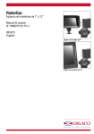
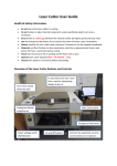
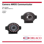
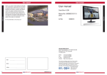
1
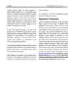
RadarEye
Sets with 7” and 12” Monitor
User manual
No. UM0972110 R1-3
08/2013
English
Set with 7” Monitor
Set with 12” Monitor
User manual
User Manual
Sets with 7” and 12” Monitor
RadarEye
Manual No. IM0972110, R1-2
ContentsPage
1. Introduction
2. RadarEye set configuration
3. Monitor settings
3.1. Orlaco monitor keyboard
3.2. Service menu
3.3. Internal Buzzer
4. Radar settings
4.1. Program the Sensor
4.1.1. Change sensor direction
4.1.1.1. Connect switch wires
4.1.2. Change Radar type
4.1.3. Change range
4.1.4. Set seperation distance
4.1.5. Moving sensitivity and non-moving sensitivity
4.2. Connecting Cameras and Sensors
4.3. Overlays
4.4. System settings
4.4.1. Setting zone to start the audible warning
4.4.2. Settings of the switch wires
4.4.3. External speaker settings
4.4.4. External messages
5. Diagnostics
6. Operation
6.2. Temporarily switch sound off (detection)
6.3. Check views displayed
6.4. Sensor failure
7. Overview of menus
2
3
4
6
6
6
6
7
7
7
7
7
8
8
8
8
9
10
10
11
11
11
13
13
13
14
14
15
UM0972110 R1-3
User manual
1. Introduction
Check with Orlaco which language versions are available. This
manual contains user instructions. Used photographs and
illustrations give general information and may differ from the
products you use.
Contact your Orlaco dealer if you have questions, additional
information, or want to make changes that are not described in this
manual.
The camera/Monitor systems from Orlaco comply with the latest
CE, ADR, EMC and mirror-directive regulations. All products are
manufactured in accordance with the ISO 9001 quality management
system, ISO/TS16949 quality automotive and ISO 14001 environmental management systems.
Available documentation
System Manual IM0974110 for installation.
Data sheet DS0208371 Monitor 7” LEDD CAN SRD 6
Data sheet DS0208871 Monitor 7” RLED CAN SRD R6
Data sheet DS0209110 Monitor 7” RLED CAN SRD 4 CAM 7-4
Data sheet DS0411300 Set Monitor 12” RLED CAN SRD R6
Release notes
R1-0 First issue, August 2013
R1-1 Article names changed, October 2013
R1-2 Chapter 7 added, November 2013
R1-3 Multiple text changes, March 2014
UM0972110 R1-3
3
User manual
2. RadarEye set configuration
Set Article No. 0403100 Set SRD Center Rear, consisting of 2
wide beam Sensors (70° beam width, 11° beam height) that work
together to guard a wide area, see figure 1.
RadarEye set center rear, system overview
Camera C
Monitor A
B
Set Art. No. 0403100
E
Master
Power
Slave
M(green)
(green)F
D
K
Terminator
1
2
Zones
3 4
5
Interface
(red)F
M(red)
range = 2m...20m
Set SRD Center Rear, Art. No. 0403100
consisting of:
2 x Art. No. 0004320 SRD sensor CAN vertical
1 x Art. No. 0401320 Bracket SRD Sensor center rear
1 x Art. no. 0301080 0,25m M12 M-S Red
1 x Art. No. 0350110 M12 Terminator 120 Ohm
Figure 1
Explanation
A - Monitor
B - Camera Cable
C - Camera
4
D - Radar Cable
E - Radar Set, center rear
K - Radar connecting cable
UM0972110 R1-3
User manual
Set Article No. 0403120 Set SRD Corner Rear, consisting of 2
wide beam Sensors (70° beam width, 11° beam height) that work
together to guard a rectangular area, see figure 2.
RadarEye set corner rear, system overview
Camera C
B
Monitor A
K
M(red)
F(red)
D
Power
H
(green)F
M(green)
Master
Terminator
Set Art. No. 0403120
Interface
Zones
Separation
distance
Slave
1
2
3
4
5
n
tio
ra e
a
p c
Se stan
di 0,5m
+
range = 2m...20m
Set SRD Corner Rear, Art. No. 0403120
consisting of:
2 x Art. No. 0004310 SRD Sensor CAN Horizontal
2 x Art. No. 0401330 Bracket SRD Sensor Corner Rear
1 x Art. No. 0350110 M12 Terminator 120 Ohm
Figure 2
Explanation
A - Monitor
B - Camera Cable
C - Camera
UM0972110 R1-3
D - Radar Cable
H - Radar Set, corner rear
K - Radar connecting cable
5
Button 3
User manual
3. Monitor settings
objects
objects in
in
C3
monitor
monitorare
are C3
C2
closer
closer than
than C2
C1
they
theyappear
appear C1
3.2. Service menu
Adjustment of the monitor settings is done via the service menu.
To open the service menu, simultaneously press the camera
selection button (1), the minus button (6) and the plus button (7)
(see Figure 3). The (monitor) Service menu (see Figure 4) will
appear. The following buttons are used to navigate through the
menus:
5 - Option/previous menu: Return to the previous menu.
6 - Minus: Go to the next menu option.
7 - Plus: Go to the previous menu option.
8 - Enter: Select or enable the chosen option.
3.3 Internal Buzzer
Button 1
The monitor is equipped with an internal buzzer.
To adjust the volume of the settings (see figure 5). Select the
keyboard menu (see figure 6). Select Beeper Volume to adjust.
Default setting of the volume is 100 (see figure 7).
Keyboard sound to ALM (Alarm) as default.
When the system is equipped with an external loudspeaker (part #
0504820) and you want to de-activate the internal buzzer, open the
service menu and go to system settings (see figure 5). Select the
keyboard menu. (see figure 6).
2
1
12” monitor Keyboard
3.1. Orlaco 7” and 12” Monitor keyboard
Button 4 Buttons 1 2345678
Button No. 1 = Camera selection
7” monitor Keyboard
Button No. 2 = Auto LCD Backlight Control/Day/Night modes
8
Button No. 3 = Contrast
7
Button No. 4 = Brightness
6
Button No. 5 = Option/previous menu
5
Button No. 6 = Selection/setting 4
Button No. 7 = Selection/setting +
Button 5
3
Button No. 8 = Enter/Standby
Buttons 6
+7
Button 1
Figure 3
Figure 4
Buttons 6 +
Button 1
7
Button 2
Buttons 5,6,7,8
Settings of the external speaker are done in the radarmenu, see
chapter 4.4.3.
Figure 5
Button 3
Figure 6
6
UM0972110 R1-3
User manual
4. Radar settings
4.1. Program the Sensor
Each Sensor needs to be programmed. Programming needs to
be done with only one sensor connected to the monitor (via the
interface).
Figure 7
Open the service menu and go to system settings (see figure 5).
Select the Radar setup menu (see figure 8). Select the Sensor
Settings menu. (see figure 9).
A warning is shown in the monitor (see figure 10):
If more Sensors are connected and you enter the sensor settings,
the Sensor with the lowest ID (= sensor direction) is detected.
When Sensor have the same ID (= sensor direction) and sensor
settings are entered, shown radar type = 50. Never change this
when more than one Sensor is connected.
Changing the range will be applied at all Sensors with the lowest
and same ID.
4.1.1. Change sensor dir (see figure 12)
The sensor direction is the position of the Sensor (or master/slave
pair) on the vehicle. As a guideline their positions are according to
the setup shown in figure 12.
A master/slave pair must be programmed with the same sensor
direction.
Default sensor direction is 1.
4.1.1.1. Connect switch wires (see figure 12)
Sensor direction 1, 11 and 12 (front radars) can be switched or
activated by with the brown switch wire.
Sensor direction 5, 6 and 7 (rear radars) can be switched or
activated with the blue switch wire
Sensor direction 2,3,4 and 8,9,10 can be blocked with a speed
signal on the grey switch wire.
For settings of the switch wires, see chapter 4.4.2
4.1.2. Change radar type
The type of the Sensor can be programmed. This determines which
function the Sensor has in the system. The default Sensor type is 2.
Possible settings are:
1 = Slave to a dual sensor master (type 2 or 3)
2 = Master for corner rear setup (AND function)
3 = Master for center rear setup (OR function)
4 = Single master Sensor, not paired
5 = Single slave Sensor, paired with type 4.
UM0972110 R1-3
Figure 8
Figure 9
Figure 10
Figure 11
7
8
9
6
5
10
11
front
4
Figure 12
3
12
2
1
7
User manual
4.1.5 Moving sensitivity and non-moving sensitivity
Moving sensitivity and non-moving sensitivity are not used in the
current software.
4.2. Connecting Cameras and Sensors
The connection between cameras and sensor is programmed in the
Radar menu. The camera is “connected” to the sensor direction,
programmed in the Sensor(s).
Zones
3 4
5
Buttons 1 2345678
2
4.1.4 Set seperation dist
Set the separation Distance. This is the distance between a master
and slave.
It can only be set or changed when radar type 2 is selected, master
for corner rear setup. The default separation distance is 2,5m (25).
Max separation distance is 4,0m (40).
objects
objects in
in
C3
monitor
monitorare
are C3
C2
closer
closer than
than C2
C1
they
theyappear
appear C1
1
4.1.3. Change range
Set the range of detection. The range can be set from 20-200
decimeter, these are divided into 5 equally sized segments (see
figure 13). The default detection range is 6m (60).
Figure 13
Range = 2m...20m
Figure 14
Open the service menu and go to system settings (see figure 5).
Select the Radar setup menu (see figure 8). Select the Camera
settings menu. (see figure 14).
There can be three (View 1-3) sensor directions connected to one
camera. The number indicates the direction where the sensor is
looking as per the “clockwheel” convention. Default view 1 for Cam
1 is set to sensor direction 6, see figure 15.
Setting up Cam 1 to look at sensor 6 means that camera 1 is
looking in the same (rear) direction as sensor 6 and that the
monitor will switch to camera 1 as soon as sensor(s) 6 detects an
object (see figure 15).
Figure 15
Figure 16
Setting up Cam 1 to look at sensors 5, 6 and 7 mean that camera 1
is looking in the same (rear) direction as sensor 5, 6 and 7 and that
the monitor will switch to camera 1 as soon as either (or all) sensor
5, 6 or 7 detect an object (see figure 16).
8
UM0972110 R1-3
User manual
4.3. Overlays
The standard visible warning is with colored dots in the above right
corner in the monitor, see figure 17. It is possible to change this to
an overlay.
There are 5 pre-programmed overlays which are designed to match
with a system setting and installation of the camera and Sensors.
Each overlay is designed to match with a camera with an opening
angle of 118 degrees.
Selected overlay is displayed on view 1, see figure 18.
Changing from the dots to an overlay can be done per camera and
is done in the camera settings in the Radar setup menu.
Open the service menu and go to system settings (see figure 5).
Select the Radar setup menu (see figure 8).
Select camera settings.
Select Overlay (see figure 18).
Figure 17
Figure 18
Overlay 1.
System: RadarEye set corner rear
Example application:
Lorry with camera at the top of the roof.
Mounting height camera: 3900mm
Camera rotated down: 42º (Bumper of lorry is shown)
Separation distance:
2750mm
6000mm
Detection range:
Overlay 1
Overlay 2.
System: RadarEye set corner rear
Example application:
Lorry with camera at the bumper.
Mounting height camera: 1000mm
Camera rotated down: 42º (Bumper of lorry is shown)
Separation distance:
2750mm
Detection range:
6000mm
Overlay 2
Overlay 3.
System: RadarEye set center rear
Example application:
Dumptruck with camera at the bumper.
Mounting height camera: 1600mm
Camera rotated down: 78º
Detection range:
10000mm
UM0972110 R1-3
Overlay 3
9
User manual
Overlay 4.
System: RadarEye set corner rear
Example application:
Wheelloader with camera at the motorcover.
Mounting height camera: 2600mm
Camera rotated down: 42º
Separation distance:
3100mm
Detection range:
15000mm
Overlay 4
Overlay 5.
System: RadarEye set center rear
Example application:
Reachstacker with camera at the counterweight
Mounting height camera: 2500mm
Camera rotated down: 45º
Detection range:
10000mm
Overlay 5
The colors of the displayed overlay differ from the shown pictures:
Zone 5 and 4 are green, zone 3 and 2 are yellow and zone 1 is red.
The camera must be positioned according to the chosen setup and
overlay.
4.4. System settings
In the system setting menu, the start of the audible warnings, the
activation of the switch wires and the settings of the external buzzer
(optional) can be done.
4.4.1. Setting zone to start the audible warning
The detection range, chapter 4.1.3, is automatically divided into 5
equally sized segments. In this menu the zone where the audible
warning is active can be set.
Open the service menu and go to system settings (see figure 5).
Select the Radar setup menu (see figure 8).
Select the Systems settings menu. (see figure 19).
Choose a zone by ‘buzzer starts at’ (see figure 20). There are five
zones to be set.
Figure 19
Figure 20
See chapter 3.3.1 for an explanation for the adjustment of the
volume of the internal buzzer.
10
UM0972110 R1-3
User manual
4.4.2. Settings of the switch wires
As explained in chapter 4.1.1.1
The sensor directions can be activated via a switch wire. See figure 21.
When switch front radars is on (figure 21) sensor directions 1,
11
and 12 are only active when the brown switch wire is “high”.
Figure 21
When switch rear radars is on (figure 21) sensor directions 5, 6
and 7 are only active when the blue switch wire is “high”(Default).
With the option Block side (figure 22), speed > sensor directions
2,3,4 and 8,9,10 are blocked with a speed signal on the grey
switch wire.
The speed is adjustable: OFF,5,10,15,20,25,30,35,40,45,50 km/h
For example
When RadarEye is applied in a rearview system, set sensor
direction to 5,6 or 7 and connect the blue wire to the reverse
signal. Camera is always active, but RadarEye is only active when
reverse is active.
How to set the Tacho Pulses
Select system settings. Press enter to open the ‘System settings’
menu. See figure 8. Use the minus (6), or the plus key (7) to go
to the option Front Camera. This option opens the front camera
sub menu of the monitor.
This offers the option Pulses per metre;
Set the amount of pulses per metre that is sent to the monitor of
the tacho switching wire (AUX1, grey), see also Frontcam Manual
IM0993850.
Figure 22
Figure 23
4.4.3. External speaker settings
Optional the 0504820, Interface Box with Ext. speaker CAN/SRD/
camera is available. This is an interface box with external speaker
and a LED light. For this external speaker, the settings can be
adjusted. See figure 23.
Ext. buz. start at:
The zone where the audible warning on the external speaker starts
can be adjusted.
Ext. buzzer volume:
Adjusting the volume of the external speaker.
Ext. LED lights at:
The zone where the visible LED warning on the external speaker
starts can be adjusted.
UM0972110 R1-3
11
User manual
4.4.4. External messages
The optional 0504820, Interface Box with Ext. speaker CAN/SRD/
camera has the possibility to send out external signals about the
detection.
These signals are RS232 en RS485 stop indications output.
There is also a possibility to connect an external indicator (for
example tower light). This external device is switched via a relais in
the 0504820.
Settings of the relais are done in the systems setting in the radar
menu, See figure 24:
Figure 24
Relais activates at:
The zone where the signal output on the relais starts can be
adjusted.
More info about the external messages and connections can be
found in the datasheet and system manual.
Orlaco Radar monitor will report the detected zone 10 times per
second on the RS232 interface.
RS232 parameters: 9600 baud, 8 bits, no parity.
The following packet will be sent: 0x80 0x01 0x40 0x03 <Status>
<Zone> 0xFF, no packet within 200ms indicates total radar system
failure.
The Status byte can have the following values:
Status value
Meaning
<Status> = 0 => No Error
<Status> = 1 => Error detected, zone detection not reliable
The Zone byte can have the following values:
Zone value
Meaning
<Zone> = 0
=> No Object
<Zone> = 1
=> Closest zone (Red)
<Zone> = 2
=> Yellow
<Zone> = 3
=> Yellow
<Zone> = 4
=> Green
<Zone> = 5
=> Farthest zone (Green)
12
NOTE:
ORLACO PRESENTS THE
RADAR SIGNAL AVAILABLE,
BUT WILL NOT BE LIABLE IF IT
IS USED TO INTERVENE IN THE
MACHINE.
UM0972110 R1-3
User manual
5. Diagnostics
This will give you an overview of the RadarEye system.
objects in
monitor are C3
closer than C2
they appear C1
Buttons 1 2345678
Open the service menu and go to system settings (see figure 5).
Select the Radar setup menu (see figure 8). Select the Diagnose
radar syst. menu (see figure 25).
When activating the Diagnose radar syst menu the shown mode is
Zone.
With the enter button (8) you can change mode to: Zone, Type,
Range and Distance (see figure 26).
–
Indicates that that specific sensor is not used/
allocated to a camera.
OK
Allocated and connected sensor (OK = no object in range) or the distance to the object in range with colored dots.
Data
Means that data is received from that sensor. However, the sensor is not allocated to a camera.
NotDet Means that the sensor is allocated to a camera, however, no data is received from a sensor with that ID.
Err01
Means there is no communication between Master and Slave
6. Operation
6.1. RADAR OK displayed
All measurable parameters and the flow of data from all connected
sensors are diagnosed and OK. There is no fault message detected
from the sensors and the sensors are operative, there are no
measurable sensor errors and detections of objects.
The range indicator in the display gives the operator a relative
distance measurement to the closest detected object. Indicate 5
dots operate from the left (green) to right (red), with a closer object
resulting in more dots. See figure 27.
Figure 25
Figure 26
Zone 5
Zone 4
Zone 3
Zone 2
Zone 1
Figure 27
The buzzer sounds audible tones to alert the operator to obstacles.
The buzzer tone rate will increase as the vehicle gets closer to an
object.
6.2. Temporarily switch sound off (detection)
Press on the ‘Option/previous’ button(5) to put the buzzer off and
the camera locked. (when a object disappears the system will
reboot automatically).
UM0972110 R1-3
13
User manual
6.3. Check views displayed
When “check views” is displayed in the monitor, RadarEye has
detected an object but camera is manually locked. The LED next to
button 1 is blinking.
6.4. Sensor Failure
If the buzzer sounds and a red cross is displayed; the sensor has
failed. Please check the Sensor or connections.
14
UM0972110 R1-3
User manual
7. Overview of menus
Service menu
Camera- + Minus- and Plus buttons
Service menu
Camera settings
Camera tags
System settings
Info
*
*
System settings
Language
On screen display
Keyboard
Power settings
CAN-bus
LCD-Backlight
Scanning
Camera switch
Frontcam
Default settings
Radar setup
Ext. device config
*
*
*
*
*
*
*
*
*
*
*
Radar setup
System settings
Camera settings
Sensor settings
Diagnose radar syst
System settings
Buzzer starts at
Switch front radars
Switch rear radars
Block side speed >
Ext. buz. start at
Ext. buzzer volume
Ext. LED lights at
Relais activates at
Camera settings
View 1
View 2
View 3
Overlay
Sensor settings
Change senser dir.
Change radar type
Change range
Set separation dist
Moving sensitivity
Non-moving sens.
OFF, 1, 2, 3, 4, 5
ON/OFF
ON/OFF
40, 45, 50
OFF, 5, 10, 15, 20, 25, 30, 35
OFF, 1, 2, 3, 4, 5
0-100
OFF, 1, 2, 3, 4, 5
OFF, 1, 2, 3, 4, 5
OFF, 1-12
OFF, 1-12
OFF, 1-12
OFF, 1, 2, 3, 4, 5
1-12
1-7
20-200
10-40
0-100
0-100
Diagnose radar syst
*These menus are explained in the User Manual UM0972080
UM0972110 R1-3
Zone
Type
Range
Distance
15
ORLACO
Orlaco is a Manufacturing company that specializes in making cameras and
monitor systems for commercial vehicles, fork-lift trucks, cranes, off shore
and maritime.
Our objective is to design and produce camera systems for the professional
market that improve the drivers’ view and increase operating efficiency.
At our facility in Barneveld we locate our design, manufacturing, warehousing
and service department.
Vision is our mission. Orlaco therefore deploys the development, manufacture,
supply and service of camera and Monitor systems that will improve safety
and efficiency of all vehicles, machinery and vessels. Our systems give the
end user a view on each blind spot and will create comfort and improved
working conditions. Our active approach will support market demands and
innovations and will lead to enthusiastic ambassadors in the market; our
customers.
For more information: www.orlaco.com
ORLACO PRODUCTS BV
Albert Plesmanstraat 42, 3772 MN Barneveld
PO Box 193, 3770 AD Barneveld
The Netherlands
Phone: +31 (0) 342 404555
Fax:
+31 (0) 342 404556
E-mail:[email protected]
Internet:http://www.orlaco.com