1
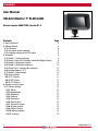
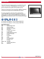
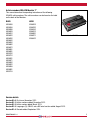
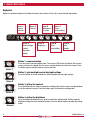
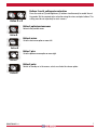
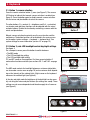
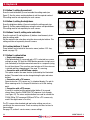
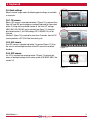
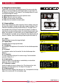
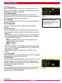
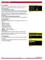
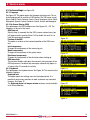
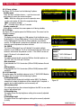
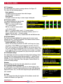
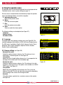
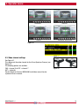
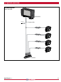
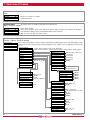
Monitor 7" RLED/LEDD
User manual
No. UM0972080 R1-4
11/2012
English
Monitor 7" RLED
Monitor 7" LEDD
Contents
User Manual
ORLACO Monitor 7” RLED/LEDD
Manual number IM0972080, Version R1-4
Monitor 7” RLED
ContentsPage
1. Quick Reference
6
2. Getting Started
8
2.1. Disclaimer8
2.2. Description of the Keyboard
8
2.3. Language setting for the OSD menu
8
3. Keyboard
9
3.1. Button 1. Camera selection
9
3.2. Button 2. Auto LCD Backlight Control/Day/Night settings
9
3.3. Button 3. Setting the contrast
10
3.4. Button 4. Setting the brightness
10
3.5. Button 3 en 4. setting color saturation
10
3.6. Locking buttons 2. 3. 4.
10
3.7. Button 5. Option button
10
3.8. Quick settings
11
3.8.1. TIC Camera
11
3.8.2. AFZ Camera
11
3.8.3. CCC Camera
11
4. Using the service menu
12
4.1. Camera settings
12
4.1.1. Mirror
12
4.1.2. Upside down
12
4.1.3. Brightness12
4.1.4. Contrast12
4.1.5. Saturation
12
4.1.6. Switch delay
12
4.1.7. Horizontal marker
12
4.1.8. Marker position
12
4.1.9. Vertical marker
13
4.1.10. Marker position
13
4.1.11. Graticule
13
2
UM0972080 R1-4
4.1.12. Cinema mode
4.1.13. Camera type
4.1.14. Video stndrd
4.1.15. Backlight
4.1.16. Zero Lux
4.1.17. Stabilizer
4.1.18. Color LUT (look up table)
4.1.19. TIC DDE (TIC digital detail enhancement)
4.1.20. Spot meter
4.1.21. Pan/tilt
4.2. Camera tags
4.3. System settings
4.3.1. Language
4.3.2. On Screen Display (OSD)
4.3.3. Keyboard
4.3.4. Power settings
4.3.5. CAN bus
4.3.6. LCD Backlight
4.3.7. Scanning
4.3.8. Camera switch
4.3.9. Front camera
4.3.10. Default settings
4.3.11. External device configuration
4.4. Info
5. Using the operator menu
5.1. Language
5.2. Camera settings
5.3. Video channel settings
6. System overview
7. Overview of menus
8. FAQ
UM0972080 R1-4
13
13
13
13
13
14
14
14
14
14
14
15
15
15
15
16
16
16
17
17
17
17
17
17
18
18
18
19
20
22
23
Monitor 7” LEDD
3
Introduction
Check with Orlaco which language versions are available. This manual
contains user instructions. Used photographs and illustrations give
general information and may differ from the products you use.
Contact your Orlaco dealer if you have questions, additional information,
or want to make changes that are not described in this manual.
The camera and monitor systems from Orlaco comply with the
latest CE, ADR, EMC and mirror-directive regulations. All products are
manufactured in accordance with the ISO 9001 quality management,
ISO/TS16949 quality automotive and ISO 14001 environmental management.
Monitor 7” RLED
For installation Orlaco Monitor 7” RLED see Manual IM0973270.
For installation Orlaco Monitor 7” LEDD see Manual IM0973260.
Used abbreviations
ABC
= Auto Backlight Control
AFZ
= Auto Focus Zoom
AGC
= Automatic Gain Control
BHO
= Black Hot
CCC
= Compact Color Camera
LUT
= Look Up Table
DDE
= Digital Detail Enhancement
FFC
= Flat Field Correction
FUS
= Fusion
I&F
= Ice and Fire
NTS
= NTSC
OSD
= On Screen Display
PTZ
= Pan & Tilt Zoom
RB
= Rainbow
Stndrd = Std = Standard
TIC
= Thermal Image Camera
WHO
= White Hot
4
UM0972080 R1-4
Article numbers ORLACO Monitor 7”
This manual describes the operating instructions of the following
ORLACO article numbers. The article numbers can be found on the label
on the back of the Monitors.
RLED LEDD
0208500
0208550
0208590
0208603
0208612
0208622
0208632
0208642
0208652
0208662
0208672
0208681
0208691
0208702
0208712
0208831
0208871
0208902
0208922
0208950
0208991
0209110
0208203
0208232
0208242
0208312
0208361
0208371
0208422
Back side Monitor 7” LEDD
Version details
Version R1-0. First issue, November 2012.
Version R1-1. Article numbers added, December 2012.
Version R1-2. Article number added, March 2013.
Version R1-3. Languages (3), CAN-ID, extra AUX wire function added, August 2013.
Version R1-4. Barcode added, September 2014.
UM0972080 R1-4
5
1. Quick Reference
Keyboard
Below is a brief description of the button functions. See sections 3 and 4 for a more detailed explanation.
Button 1
Camera
selection
Button 5
Option/previous menu
Button 3
Contrast
Button 7
Plus +
select/setting
objects in
monitor are
closer than
they appear
Button 2
Auto backlight
control
day/night
modes
Button 4
Brightness
Button 6
Minus select/setting
Button 8
Enter /
standby
Button 1, camera selection
Button 1
Press the camera selection button once. The camera LED flashes to indicate that manual
camera selection is enabled. Use the minus and plus buttons to select the camera. Press
the button again to disable manual camera selection.
Button 1
Button 2, auto backlight control day/night settings
Press this button to switch between the auto backlight day and night settings.
Button 2
Button 2
ButtonButton
2
3, setting the contrast
Press the button once in order to enable the setting mode. Use the minus and plus buttons
to set the required contrast. Press the button again to disable the setting mode.
utton 3
Button 3
Button 3
Button 4, setting the brightness
Button 4
Button
3
Press
the brightness
button once in order to enable the setting mode. Set the required
brightness using the minus and plus buttons. Press the button again to disable the setting
mode.
Button 4
Button 4
6
Button 4
UM0972080 R1-4
3
Buttons 3 and 4, setting color saturation
4
Button 4
Button 3
Press the contrast (3) and brightness (4) buttons simultaneously to enable the setting mode. Set the required color saturation using the minus and plus buttons. This
setting must be set separately for each camera.
+4
Button 5, option/previous menu
5
Return to the previous menu.
Button 5
Button 5
n6
Button 6, minus
Go to the next menu option or move left.
Button 6
Button 6
Button
Button
6 7, plus
Go to the previous menu option or move right.
Button 7
Button 7
8, enter
ButtonButton
7
Switch to Standby or in the menus, select or activate the chosen option.
Button 7
Button 8
Button 8
Button 8
Button 8
UM0972080 R1-4
7
2. Getting started
2.1. Disclaimer
When switching on the monitor for the first time, a disclaimer appears in
English for 5 seconds (see Figure 1).
Displayed text: Do not operate display functions during safety critical
operations. Objects in the monitor are closer than they appear. If a different language is subsequently set, the disclaimer text appears in the
set language.
objects in
monitor are C3
closer than C2
they appear C1
Buttons 1 2345678
2.2. Description of the keyboard
Button no. 1 = Camera selection
Button no. 2 = Auto LCD backlight control day/night settings
Button no. 3 = Contrast
Button no. 4 = Brightness
Button no. 5 = Option/previous menu
Button no. 6 = Minus selection/setting button (-)
Button no. 7 = Plus selection/setting button (+)
Button no. 8 = Enter/Standby
Figure 1
2.3. Language setting for the OSD (On Screen Display) menu
The OSD menu language is set as English by default. If you would like to
operate the OSD menu in a different language, open the service menu
→ system settings. See section 4 on page 13. The OSD menu is available in English, Dutch, German, French, Chech, Hungarian, Italian, Polish,
Portuguese, Spanish, Turkish, Swedish, Finnish, Danish and Norwegian.
8
UM0972080 R1-4
3. Keyboard
3.1. Button 1, camera selection
Button 3
Press the camera selection button (1) once (see Figure 2). The camera
LED flashes to indicate that manual camera selection is enabled (see
Figure 3). Press the button again to disable manual camera selection.
Use the minus and plus buttons to select the camera.
The other buttons (3 = contrast, 4 = brightness andButton
3+4 = saturation)
4
can also be used and these functions can be adjusted with the minus
and plus buttons. Disable the function by reselecting a camera with the
minus and plus buttons.
Manual camera selection has priority over the scan function and the
switchwires. The button function can be disabled in the service menu
5
via the option 'system settings → keyboard → keyboard lock'.Button
See
system settings for more information (section 4.3. on page 13).
objects in
monitor are C3
closer than C2
they appear C1
Buttons 1 2345678
Button 1
Figure 2
Button 1
Button 1
Button 1
3.2. Button 2, auto LCD backlight control day/night settings
See figure 4.
For a compact camera, press this button to switch between:
• The ABC mode
• The LCD backlight day setting
• The LCD backlight night setting
TIC and AFZ cameras are exceptions. For these, pressing button 2
makes other functions available (see sections 3.8.1. and 3.8.2. on page
9).
The ABC mode controls the backlight between a minimum (adjustable;
see also under service menu on page 16) and a maximum level depending on the intensity
of the 1
ambient light. A light sensor on the keyboard
Button
measures the ambient light (see Figure 6).
Figure 3
Button 1
Button 1
Buttons 6 +
7
Button 2
Button 2
Button 2
Figure 4
Buttons 6
+7
Butt
Butto
In the day and night mode the brightness of the backlight can be manually set using the minus and plus buttons (the settings are saved). These
settings are not camera dependent and therefore apply for all cameras
(see Figure 5).
Button 3
Figure 5 5,6,7,8
Buttons
But
Figure 6
UM0972080 R1-4
9
Button 1
3. Keyboard
3.3. Button 3, setting the contrast
Button 1
Button 1
Press the contrast button (3) once to enable the setting mode (see
Figure 7). Use the minus and plus buttons to set the required contrast.
This setting must be set separately for each camera.
objects in
monitor are C3
closer than C2
they appear C1
Buttons 1 2345678
Button 2
Button 2
3.4. Button 4, setting the brightness
Press the brightness button (4) once to enable the setting
mode (see
Button
2
Figure 8). Set the required brightness using the minus and plus buttons.
This setting must be set separately for each camera.
Button 3
3.5. Buttons 3 and 4, setting color saturation
Button
Figure
7 3
Press the contrast (3) and brightness (4) buttons simultaneously to enable the setting mode.
3
Set the required color saturation using the minus and plus buttons. Button
This
setting must be set separately for each camera.
Button 4
3.6. Locking buttons 2, 3 and 4
These buttons can be locked in the service menu (section 4.3.3. keyboard, see page 13).
3.7. Button 5, option button
Button 4
Figure
8 4
Button
• Single scan sequence
If the option button (5) is pressed and a CCC is selected (see camera
settings on page 10), then the LEDD Monitor generates a single scan
(not continuous) of multiple connected cameras in a sequence (using
the set time interval. The scan time must only be set if the main scan
is started and then stopped again). See page 15, scanning.
• Connection with an AFI/AFZoom camera
Figure 9
This option enables the zoom function (indicated by the illuminated
button). The zoom factor can be changed using the plus and minus
buttons.
• Connection with a TIC camera
Zoom factors for a TIC camera are: 1x (standard display), 2x and 4x.
When zooming out to 1x, the pan/tilt function is set at the starting
point.
• Connection with a PTZ camera
If pan/tilt is enabled and the option button (button 5) is pressed
several times, then the ZOOM, PAN, TILT sequence is run through
Button 1
(see Figure 10). The minus and plus buttons are used to activate the
ZOOM, PAN or TILT movement (PAN and TILT for a TICButton
camera1only
work if the digital zoom is 2x or 4x).
Button 1
The TIC camera video standard and spot meter settings are only accessible via the camera menus. There are no keys for direct access to
these settings.
See page 10, section 4: service menu, camera settings.
10
Button
Button 5
Button 5
Button
Buttons 6
+7
Button
Buttons 6
+7
UM0972080 R1-4
Button
3. Keyboard
3.8. Quick settings
When in normal image mode, the following quick settings are available
as shortcuts:
3.8.1. TIC camera
When a TIC camera is selected and button 2 (Figure 12) is pressed, then
Color LUT and DDE quick settings are enabled (indicated by illuminated
button 2). Using the minus button (button 6), the Color LUT settings
(WHO, BHO, FUS, RB, I&F) can be selected (see Figure 11). Using the
plus button (button 7), the DDE settings (OFF, LOW, MED, HI) can be
selected.
If button 2 (Figure 12) is pressed for more than 3 seconds, then the TIC
camera performs a FFC (Flat Field Correction) cycle.
Figure 10
Button 1
3.8.2. AFZ camera
If an AFZ camera is selected and button 2 is pressed (Figure 12), then
the zero lux and backlight functions of the AFZ camera are enabled/
disabled.
Figure 11
Button 1
3.8.3. CCC camera
If a CCC is selected, then pressing button 2 (Figure 12) switches between all backlight settings for the entire system (DAY, NIGHT, ABC). See
section 3.2.
Button 2
Figure 12
Button 3
But
UM0972080 R1-4
11
4. Service menu
4. Using the service menu
To open the service menu, simultaneously press the camera selection
button (1), the minus button (6) and the plus button (7) (see Figure 13).
The Monitor (see Figure 14) will appear. The following buttons are used
to navigate through the menus:
5 - Option/previous menu: Return to the previous menu
6 - Minus: Go to the next menu option
7 - Plus: Go to the previous menu option
8 - Enter: Select or enable the chosen option
Button 5
objects
objects in
in
C3
monitor
monitorare
are C3
C2
closer
closer than
than C2
C1
they
theyappear
appear C1
Buttons 1 2345678
Buttons 6
+7
Button 1
4.1. Camera settings
Select camera settings. Press enter to open the 'Camera settings' menu. Use
the minus (6) and plus (7) buttons to select which camera to configure. Then
confirm this selection by pressing the enter button (8). The yellow cursor is
Button 1
now activated in the list of items. Use the minus (6) and plus (7) buttons to
select the item to adjust and then confirm this selection by pressing the enter
button. If the selection is an on/off switch, you can choose between on and
off. If the selection is a number, you can change the value using the minus (6)
and plus (7) buttons. Save the new settings by pressing the enter button (8).
4.1.1. Mirror
Enable this option to reverse the image (left/right).
4.1.2. Upside down
This option flips the image (upside down).
4.1.3. Brightness
The setting for the brightness of the monitor. For direct button operation:
Button 4.
4.1.4. Contrast
The setting for contrast on the monitor. For direct button operation:
Button 3.
4.1.5. Saturation
The color saturation setting for the camera image. For direct button
operation: Buttons 3+4.
4.1.6. Switch delay
Enable this option if the switchwire is controlled by an intermittent
signal (e.g. from an indicator light).
4.1.7. Horizontal marker
Enable this option to show a reference line. The reference line is displayed as a horizontal green line. See Figure 40 on page 19.
4.1.8. Marker position
Adjusts the vertical height of the reference line. 0 corresponds to the top
edge of the monitor and 100 to the bottom edge.
12
Figure 13
Figure 14
Figure 15
Buttons 6 +
Button 1
7
Button 2
Buttons 5,6,7,8
Button 3
Figure 16
UM0972080 R1-4
4. Service menu
4.1.9. Vertical marker
Enable this option to show a reference line. The reference line is displayed as a vertical green line. This option is not available on all RLED/
LEDD models. See Figure 40 on page 19.
4.1.10. Marker position
Adjusts the vertical position of the reference line. This can be set
between 38 and 63. The left and right sides swap position depending on
the settings of the camera mirror-image function.
4.1.11. Graticule
This option shows a graticule for a rearview camera on the monitor. See
Figure 40 on page 17.
4.1.12. Cinema mode
The camera image is displayed in widescreen when this option is
enabled.
4.1.13. Camera type
Select the camera type that is connected. The special features of that
camera type will then become available. The camera types that can be
selected are:
AFZ: Enable this option if an AFI/AF zoom camera is connected. If AFZ
is selected, the backlight, zero lux and stabilizer options are enabled.
Operation of the zoom function:
Button 5 - Enable the zoom function. The zoom function is disabled if the button is pressed again.
Button 6 - Zoom out.
Button 7 - Zoom in.
TIC: Enable this option if a Thermal Image Camera (TIC) is connected.
If TIC is selected, then the video standard, color LUT, TIC DDE and spot
meter options are enabled.
CCC: Enable this option if a Compact Color Camera (CCC) is connected.
4.1.14. Video stndrd
Video standard: The camera type must be set to TIC. Select the standard
video output for the camera: PAL or NTSC (NTS).
4.1.15. Backlight
This option corrects the background light in order to improve the screen
Monitor of dark objects in bright/lit surroundings. This option is only
available if an AFZ camera is connected to a serial 7" RLED/LEDD Monitor. For direct button operation: Button 2.
4.1.16. Zero lux
Enable this option to improve the light sensitivity of the camera in dark
surroundings. This option is only available if an AFZ camera is connected to a serial 7" RLED/LEDD Monitor.
UM0972080 R1-4
Figure 17
Depending on the choice of
camera type (see Figure 17), the
settings marked in blue will or
will not be available.
Figure 18
13
4. Service menu
4.1.17. Stabilizer
This option enables the stabilizer function, if the camera has one. This
option is only available if an AFZ camera is connected to a serial 7"
RLED/LEDD Monitor.
4.1.18. Color LUT (look up table)
The camera type must be set to TIC. Select the color palette to be used
to give the correct color temperature. Select from WHO (white hot), BHO
(black hot), FUS (mixed), RB (rainbow) and I&F (ice and fire). The AGC
(automatic gain control) is automatically set for the WHO, BHO, FUS and
RB settings.
4.1.19. TIC DDE (TIC digital detail enhancement)
Possible settings are: OFF, LOW, MED and HI. Select the desired degree
of image enhancement.
4.1.20. Spot meter
Only works if TIC is selected as the camera type (see section 4.1.10. on
page 11):
OFF (spot meter off)
B C (bar in Celsius)
B F (bar in Fahrenheit)
N C (number in Celsius)
N F (number in Fahrenheit)
BNC (bar + number in Celsius)
BNF (bar + number in Fahrenheit)
4.1.21. Pan/tilt
Enabling the pan/tilt function makes standard pan and tilt operation
possible (option button = button 5). It is possible to use digital pan/tilt
when the TIC image is zoomed 2x or 4x.
Figure 19
4.2. Camera tags
See Figure 20. In this menu, names can be given to the camera inputs.
See Figure 21.
The number of inputs depends on the video switch type that is set (see
section 4.3.8. on page 15).
Figure 20
Figure 21
14
UM0972080 R1-4
4. Service menu
4.3. System settings (see Figure 22)
4.3.1. Language
See Figure 23. This option opens the language selection menu. The selected language will be used for all OSD menus. The OSD menu is available in English, Dutch, German, French, Chech, Hungarian, Italian, Polish,
Portuguese, Spanish, Turkish, Swedish, Finnish, Danish and Norwegian.
4.3.2. On Screen Display (OSD)
This option opens the OSD settings menu. See Figures 24 + 25. The
following can be set in this menu:
OSD time-out
Sets the time (in seconds) that the OSD (camera number/name, top
left) appears on the monitor. Select 'Off' to disable this and 'On' to
have this permanently enabled.
Position of the OSD
This option is used to set the horizontal position of the OSD menu
text.
Info transparency
Changes the transparency of the camera tag, etc.
Menu transparency
Changes the transparency of the system menu.
Disclaimer transparency
Changes the transparency of the disclaimer when starting up.
OSD menu help
This function enables or disables the automatic text messages of the
OSD help menus. If enabled, help messages automatically appear in
all menus after 10 seconds of inactivity.
4.3.3. Keyboard
This option opens the keyboard menu. See Figure 26. This menu has the
following 3 options:
Keyboard lock
This option opens the settings menu for the keyboard lock. It is
possible to lock various functions in order to prevent any unwanted
changes. See Figure 27.
The keyboard sound and beeper volume functions are not available
on all Orlaco Monitors.
Figure 22
Figure 23
Figure 24
Figure 25
Figure 26
Figure 27
UM0972080 R1-4
15
4. Service menu
4.3.4. Power settings
See Figure 28. This menu has the following 2 options:
Standby mode
There are three available choices — use the minus and
plus buttons to select the various functions.
MNU = With this setting you access the operator menu
via the enter button (8). Select the required setting.
Figure 28
IMM = Immediate standby.
2S = Standby after a delay of 2 seconds.
Standby, camera off
If this option is enabled, the camera power is off during standby.
4.3.5. CAN bus
See Figure 29. This option opens the CAN bus menu. This menu has the
following 4 options:
CAN protocol
This option selects the signal, or CAN protocol, that the Monitor uses.
By default this is Orlaco CAN protocol 1. For the Orlaco Radar system*:
Orlaco CAN protocol 6 must be set. Other protocols are customerspecific. The CAN speed is automatically adjusted, but it can also be set
manually once the protocol has been selected.
Set CAN-ID
Figure 29
The Orlaco CAN protocol has an ID (default 0) to control multiple
* Article No:
monitors via one CAN bus. The ID is inactive when the text is blue and
0208871
becomes active when the protocol is set to 1. The CAN-ID can be set
from 0-15 where 0 is the default value.
Monitor 7” RLED CAN Radar 6
CAN speed
0208371
This option selects the bit rate of the CAN bus. Available options are:
Monitor 7” LEDD CAN Radar 6
100, 125, 200, 250, 500 and 1000 kbit.
Main terminator
Enable/disable the 120 Ω terminator (CAN or RS485) between Rx and
Tx.
AUX terminator
Enable/disable the 120 Ω terminator (CAN or RS485) between AUX1
and AUX2.
4.3.6. LCD backlight
This option opens the backlight submenu for the 7" RLED/LEDD Monitor.
See Figure 30. This menu has the following 4 options:
LCD backlight mode
This option enables automatic backlight control (ABC). The Monitor
Figure 30
automatically adapts its brightness to the ambient light. If required, a
specific day or night brightness can be manually set.
ABC minimum level
This setting determines the minimum brightness the ABC can use when
there is low ambient light.
LCD backlight day
This option allows the day brightness setting to be manually adjusted
(50–100%).
LCD backlight night
This option allows the night brightness setting to be manually adjusted
(0–50%).
16
UM0972080 R1-4
4. Service menu
4.3.7. Scanning
This option opens the camera scanning submenu. See Figure 31.
This menu has the following options:
Scan sequence
This option selects the cameras from which images
are to be shown in sequence.
Scan interval
This option selects how long a camera image is displayed.
4.3.8. Camera switch
This option configures the type of video
switch that is used. See Figure 32.
'OFF' if no camera switch is used
→ 1 camera system.
'3C' for an external camera switch
→ 3 camera system.
'2C' if a 2–4 camera cable is used → 2 camera system.
'4C' if a combination of internal and external switches and a 2–4
camera cable are used → 4 camera system.
'QUA' for a quad system, only in combination with the Multiview box.
4.3.9. Front camera
See Frontcam manual 0993850. This option opens the front camera
submenu for the 7" RLED/LEDD Monitor. This enables the front camera
functionality (a statutory obligation).
Function AUX wire, see figure 34a
Defines the function of the AUX1 & AUX2 switching wires (grey
and yellow). Select TCH for the tachometer function (Tacho to
AUX1 and hand brake to AUX2) or ZOO for the camera zoom function (only available in combination with an auto focus camera). Use
in this case the AUX1 & AUX2 switching wires to zoom in and out.
Select KEY to block the keyboard fully by activating the wire AUX1.
4.3.10. Default settings
This option opens the menu to restore the factory default settings. Select
the number of the factory settings that you require (1 = default Orlaco
settings). You can choose between 30 sets of default settings. Contact
ORLACO for further information. Select the option 'Restore defaults' to
restore the factory settings.
Warning:
All user settings are lost when the factory defaults are restored!
4.3.11. External device configuration
This option opens the configuration menu for an external device. Only
use this option if a device is connected that has its own OSD (Multiview,
Spectrum Scanner, etc.). Exit the menu by pressing the option button (5)
for 3 seconds.
Figure 31
Figure 32
Figure 33
Figure 34
Figure 34a
4.4. Info
This user manual describes the functions of the software version indicated on this Monitor (see Figure 35).
UM0972080 R1-4
Figure 35
17
Button 4
5. Operator menu
5. Using the operator menu
objects in
monitor are C3
closer than C2
they appear C1
The operator menu is not available by default due to the keyboard lock.
Buttons
Button
5 1 2345678
To disable the lock, refer to system settings on page 15.
Press the minus and plus buttons simultaneously to open the operator
menu. The following buttons are used for navigation:
5 - Option/previous menu:
Return to the previous menu
6 - Minus:
Go to the next menu option
7 - Plus:
Go to the previous menu option
8 - Enter:
Select or enable the chosen option
The following settings can be adjusted (see Figure 37):
Language
Button 1
Camera settings
Set video channel
Buttons 6
+7
Figure 36
Figure 37
Buttons 6
+7
5.1. Language
This option opens the language selection menu (see Figure 38). The
selected language will be used for all OSD (On Screen Display) menus.
The OSD menu is available in English, Dutch, German, French, Chech,
Hungarian, Italian, Polish, Portuguese, Spanish, Turkish, Swedish,
Finnish, Danish and Norwegian.
Figure 38Buttons 5,6,7,8
5.2. Camera settings (see Figure 39)
Horizontal line mark
Enable this option to show a reference line. The reference line is
displayed as a horizontal green line. See Figure 40.
Line position
Adjusts the vertical height of the reference line. 0 corresponds to the
top edge of the monitor and 100 to the bottom edge.
Vertical line mark
Enable this option to show a reference line. The reference line is displayed as a vertical green line. This option is not available on all RLED/
LEDD models. See Figure 40.
Line position
Adjusts the vertical position of the reference line. This can be set
between 38 and 63. The left and right sides swap position depending
on the settings of the camera mirror-image function.
Graticule
This option shows a graticule for a rearview camera on the monitor.
See Figure 40.
18
Figure 39
UM0972080 R1-4
5. Operator menu
Graticule
Horizontal
Figure 40
Vertical
Horizontal and vertical
Figure 41
5.3. Video channel settings
See Figure 41.
This option sets the video channel for the Orlaco Spectrum Scanner (see
Figure 42).
The following options are available:
CH0 = channel 0 to CH7 = channel 7
AUT = automatic
See the Spectrum Scanner IM0004060 installation manual for descriptions of these channels.
UM0972080 R1-4
Figure 42
19
6. System overview
1 camera system
RLED Serial
power
2 camera system
With Y-split cable
RLED/LEDD
power
20
2-4 camera cable
UM0972080 R1-4
6. System overview
4 camera system
With Y-split cable
RLED/LEDD
power
2-4 camera cable
Switcher
UM0972080 R1-4
21
7. Overview of menus
Standby menu
Enter
Standby menu
Standby
Info
Monitor is on but there is no picture
Software information
Operator menu
The operator menu is not available by default due to the keyboard lock.
Minus- and Plus buttons
Operator menu
Language
Camera settings
Set video channel
English, Dutch, German,
French, Czech, Hungarian, Italian, Polish, Portuguese, Spanish, Turkish, Swedish, Finnish, Danish and Norwegian.
Horizontal Marker, Marker position, Vertical Marker, Marker position, Graticule
CH0, CH1, CH2, CH3, CH4, CH5, CH6, CH7, AUT
Service menu
Camera- + Minus- and Plus buttons
Service menu
Camera settings
Camera tags
System settings
Info
Mirror, Upside down, Brightness, Contrast, Saturation, Switch delay, Hor. Marker, Marker position, Vert. Marker, Marker position,
Graticule, Cinema mode, Camera type, Video standard, Backlight, Zero Lux, Stabilizer, Color LUT, TIC DDE, Spot meter, Pan/Tilt,
1, 2, 3
System settings
Language
On screen display
Keyboard
Power settings
CAN-bus
LCD-Backlight
Scanning
Camera switch
Frontcam
Default settings
Ext. device config
English, Dutch, German, French, Czech, Hungarian,
Italian, Polish, Portuguese, Spanish, Turkish, Swedish, Finnish, Danish and Norwegian.
On screen display
QUA, 4c, 2c, 3c, OFF
OSD timeout
OSD position
Info transparency
Menu transparency
Disclaimer transp.
OSD menu help
Keyboard
Keyboard lock
Keyboard sound
Beeper volume
ON/OFF
ON/OFF
ON/OFF
ON/OFF
ON/OFF
Standby menu
Operator menu
Camera switch
Camera settings
Standby
OFF 1c, 2c, 3c
ON/OFF
0-100
OFF, TCH, ZOO, KEY
Power settings
Default settings
Select default
Restore defaults
OFF, K+A, ALM, KEY
0-100 positions
Keyboard lock
Frontcam
Enable Frontcam
Invert handbrake
Pulses per meter
AUX wire function
ON, OFF, 30sec, 10sec, 3sec
19 positions
29 positions
29 positions
29 positions
ON/OFF
1-21
Standby mode
Standby camera off
IMM, MNU, 2sec
ON/OFF
CAN-bus
CAN-protocol
CAN-speed
Set CAN-ID
Main terminator
AUX terminator
OFF, 1-6 positions
1M, 500, 250, 200, 125, 100
0 - 15
ON/OFF
ON/OFF
LCD-backlight
LCD-backlight mode
ABC Minimum level
LCD-backlight day
LCD-backlight night
ABC, NIT, DAY
0-50
50-100
0-50
Scanning
Scan sequence
Scan interval
22
OFF, 1-2, 1-2-3
2s, 5s, 10s
UM0972080 R1-4
8. FAQ
1. Mirror setting.
• Open the service menu by pressing simultaneously the 3 buttons; camera selection, plus and minus.
• Choose camera settings, and press enter.
• Select the camera to change by plus or minus button, and press enter.
• Press enter, and see if the image is ok.
• Press 3 times on the option (escape) key.
objects in
monitor are C3
closer than C2
they appear C1
Buttons 12345678
Description of the keyboard:
See chapter 1, page 6.
2. Monitor does not change automatically, and LED flashes at camera selection.
• Press the camera selection button.
3. Monitor is on camera 3 and is not to operate.
• Press for about 15 seconds on the option (escape) key.
4. Monitor works after booting about 2 seconds and then turns off.
• Press the enter key.
5. LED-C1 and LED-enter key flashes 4x in succession.
• Contact your installer for repairs to the system
6. Setting the monitor to control an auto-focus camera.
• Open the service menu by pressing simultaneously the 3 buttons; camera selection, plus and minus).
• Choose camera settings, and press enter.
If the yellow dot does not go to C1, press repeatedly on the minus or plus key until it is able to C1.
• Press once the enter button, and then repeatedly press the
minus button until the yellow dot is placed behind camera type,
press the enter button, and then press the plus key (CCC has now turned into AFZ), press the enter button.
• Press 3 times on the option (escape) button.
UM0972080 R1-4
23
ORLACO
Orlaco is a Manufacturing company that specializes in making cameras and
monitor systems for commercial vehicles, fork-lift trucks, cranes, off shore and
maritime.
Our objective is to design and produce camera systems for the professional
market that improve the drivers’ view and increase operating efficiency.
At our facility in Barneveld we locate our design, manufacturing, warehousing and
service department.
Vision is our mission. Orlaco therefore deploys the development, manufacture,
supply and service of camera and Monitor systems that will improve safety and
efficiency of all vehicles, machinery and vessels. Our systems give the end user
a view on each blind spot and will create comfort and improved working conditions. Our active approach will support market demands and innovations and will
lead to enthusiastic ambassadors in the market; our customers.
For more information: www.orlaco.com
ORLACO PRODUCTS BV
Albert Plesmanstraat 42, 3772 MN Barneveld
PO Box 193, 3770 AD Barneveld
The Netherlands
Phone: +31 (0) 342 404555
Fax:
+31 (0) 342 404556
E-mail:[email protected]
Internet:http://www.orlaco.com