1
4-24
PC Operation
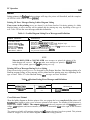
Expanded Print Format
When a more complex ladder diagram, using MCS and MCR functions, is to be printed out, an
expanded print format is used. The starting point of each MCS function is denoted by a letter, the first is
A, then B, etc. The letter is carried through to the end of each page and the beginning of the next page,
providing a ready reference to the continuation of the ladder logic within the bounds of each MCS/MCR
control. As multiple MCS functions and the logic under their control are printed, each succeeding group
of logic is shifted to the right. When a group of logic under MCS/MCR control is ended by an MCR
function, (MCR) is printed in the last column to the right and the letter corresponding to that MCS/MCR
logic to its right.
Printout Annotation Explanation
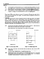
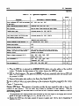
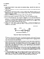
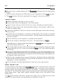
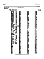
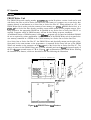
Several items appearing on the printouts in figures 4-6 and 4-7 aze explained for clarification. The ladder
diagram printout in figure 4-6 has a circled number (l-5) next to each annotation, which corresponds to
the number preceding the explanation of each annotation. The circled number 6 appears before an
annotation on the Boolean printout in figure 4-7. The circled numbers (1-6) are for discussion purposes
- only and do not normally appear on a printout.
1 . The type of printout on each page appears on this line, either LADDER DIAGRAM. PRINTOUT,
BOOLEAN PRINTOUT, or CROSS REFERENCE PRINTOUT.
2 This annotation, V X.X, is the version of the system operating software contained in PROM
memory in the Printer Interface Unit.
3 . The model of PC selected by the user as the program listing source will be on this line. The
annotation will be either SERIES ONE JR/SR-10 for a Series One Junior PC or Series One, One
Plus/SR-20, SR-21 for a Series One or Series One Plus PC.
4. ‘The page number of the ladder diagram printout or Boolean printout will appear here as a 4-digit
decimal number, starting with PAGE Oool.
5 . Refers to ladder diagram printout only. This 4-d@ decimal number is the user program memory
address at the start of each rung of logic. The fkst element in the rung is stored at that address. In
the example in figure 4-6, the memory address of the start of the first rung is 0000. The first element
in that rung is a normally open contact referenced as 001 (reference number is printed directly
above the contact). The memory address at the start of the second rung is 0013, the first element in
this rung is a normally open contact referenced as 040.
6 . Refers to Boolean printout only (figure 4-7). The # sign immediately following a numerical value in
the Boolean printout listing, indicates that the value is a reference assigned to an element at the end
of a rung.
7 . A symbol preceding a numerical value in a Boolean printout, indicates that the value is a constant.
l