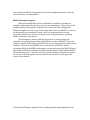
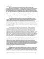
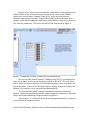
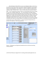
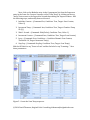
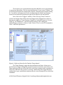
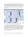
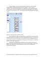
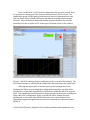
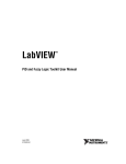
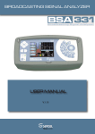
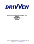
1
MICAS-X Demo Manual
This manual is a guide to getting started with MICAS-X. It is written with the
assumption that you are using the Limited Demo version of MICAS-X, but most of the
steps are identical for the full version as well. Installation will be different for the
full version, as well as some minor changes to the program name and functionality.
Note that the Limited Demo version only works for 20 minutes, after which most
functionality will stop. It is important to safely shut down any instrumentation you
may be using with the Limited Demo version before the 20 minute time limit
expires. Also, the Limited Demo version is available only as an executable, whereas
the full version can be obtained either as an executable or as LabVIEW source code.
Getting Started with MICAS-X
Refer to the MICAS-X Installation Manual for information on installing
MICAS-X on your computer. This manual is included with your MICAS-X installation
program (in the C:\OCC\MICAS-X Support\Documentation directory), or can be
obtained from the Original Code Consulting website at the following location:
http://www.originalcode.com/MICASX_Resources.html
For a more complete overview of MICAS-X software, see the MICAS-X User
Manual (available in the same locations as the Installation Manual). Only a short
overview will be given here.
MICAS-X.exe is the main program that controls the MICAS-X system. The
behavior of this program can be extensively customized through the MICAS-X
Configuration Editor. The Configuration Editor can be run as a stand-alone
executable program, or can be called from the Utilities menu when running MICAS-X.
When MICAS-X starts, it loads a configuration file specified by the user. The
configuration file determines which additional components are loaded. Any number
of Drivers can be configured to be loaded. Drivers interact with hardware to acquire
or set channel values. MICAS-X Drivers exist to support the National Instruments
Daq Devices as well as a wide range of other hardware. MICAS-X will also load any
number of Displays and Instruments. Displays provide a user interface that is
customized to a particular situation or experiment. Instruments can include a
Display, but are intended for adding more complex functionality to MICAS-X that
cannot be supported by the Driver model.
In the following example, you will create a MICAS-X configuration that
implements two Drivers. The Drivers used do not interact with hardware, but create
“virtual” channels based on user input and calculations, thus the example can be run
without the need of any specific external hardware. You will also configure a
Sequence and a Trigger in MICAS-X, as well as some of the built-in display features.
© 2014 David Thomson, Original Code Consulting, [email protected]
You can then run MICAS-X using the newly created configuration and see how the
various features are implemented.
MICAS-X Example Program
When the Limited Demo version of MICAS-X is installed, it includes an
example configuration file that allows it to be run immediately. This section of the
program leads you through the steps which re-create this same configuration.
Follow this guide to create a copy of the configuration, then run MICAS-X to see how
the functionality you configured works. Once you understand the concepts
reviewed in this process, you can create your own configurations for operating
MICAS-X with your own system.
This document is written from the perspective of someone using the
compiled, executable program of the Limited Demo version of MICAS-X. If you are
using the compiled full version of MICAS-X, the process described here will be nearly
identical. If you have the LabVIEW source code version of MICAS-X and are
operating within the LabVIEW environment, you must first open the MICAS-X.lvproj
project file and find the Configuration Editor (in the Utilities folder) and the MICASX.vi within the project. These are opened by double-clicking on them in the project.
To run one of these programs, the user must hit the run arrow in the upper left
corner of the window.
© 2014 David Thomson, Original Code Consulting, [email protected]
Introduction
MICAS-X is designed to be an highly flexible, highly extensible data
acquisition and control framework. It contains a large amount of functionality that
is needed for many instrument control situations, but is designed in a way that is
geared toward adding custom functionality as well. The core of MICAS-X is support
for “slow” data, sometimes called housekeeping data, which typically is acquired at 1
Hz. For some applications, all the instrument data may fit within this model, and
MICAS-X can be configured to handle nearly the entire system with out-of-the-box
functionality. For other systems, this housekeeping data is used to monitor the
health of the system, set up various modes of operation, trigger alarms on certain
conditions, etc.
The housekeeping data in MICAS-X is acquired by any number of “Driver”
modules. Many Drivers are already created, including modules for acquiring and
controlling analog and digital input and outputs of National Instruments Daq
devices, Drivers for reading serial or network data from streaming instruments, and
Drivers for creating manually-entered values, for creating timer channels and for
creating channels whose value is calculated from other channels by text formulas or
by LabVIEW code. Other Drivers can be quickly created for interfacing to nearly any
instrument or device.
Other modules in MICAS-X act on the Drivers data. Triggers and Alarms
continuously monitor user-defined channels and execute a user-defined action
whenever a condition is met. Sequences can be created to step through various
instrument modes based on timing or channel conditions. Data logging can be
configured to write any combination of channels to any number of data files. Errors
and events are logged and presented in an intuitive and consistent manner. Time
series graphs are available with flexible time history selection and built-in buffering
of the data. In addition, other modules can be added to extend the functionality of
MICAS-X by adding powerful Display modules and custom Instrument modules.
The example configuration created and used in this document is intended to
show many of the functions of MICAS-X without requiring connection to any
physical hardware. To do this, Manual channels are created, for which the user can
define the value. Simple Triggers and Sequences are also created to show how
MICAS-X can be automated merely though configuration options, without having to
alter or create any source code. Specifically, this example creates a demonstration in
which a temperature setpoint is ramped, and an Alarm alerts the operator when a
specific process variable temperature is exceeded.
Creating the File
To begin creating the example configuration file for MICAS-X, run the MICASX Configuration Editor. When this is run, it will first ask you to select an existing
configuration file. Click on the “Cancel” button of the file dialog window. Then click
the “New” button in the upper right hand part of the window. In the File Name field,
© 2014 David Thomson, Original Code Consulting, [email protected]
name the new file “MICAS-X Demo Configuration” when prompted. (Note that there
should be an existing configuration file named “MICAS-X Example Configuration”
which will be identical to the configuration file you will create by following these
instructions). After the file is named, click the “Mark as Start-up File” in order to tell
the MICAS-S program that this is the configuration file to use the next time the main
MICAS-X program is run. Although the new configuration file has been initialized in
the configuration editor, it does not exist on disk until some parameters have been
saved. In the MICAS configuration screen, click the “Acquire on Startup” button to
un-check it, then click it again to check it. Making this change to the parameters will
cause the “Save” button to become enabled. Click on the “Save” button to save the
new configuration file.
Figure 1. Creating the demo configuration file and marking it as the Start-up File.
© 2014 David Thomson, Original Code Consulting, [email protected]
Next, go to the Acquisition tab to select the Driver which will be used.
Double-click on each the “Manual” and “Equations”' Drivers from the “Available
Drivers” list on the right-hand side of the window to add them to the list of Drivers
configured to be used by MICAS-X. Note that the Drivers that appear in the Available
Drivers may be different than those shown in the figure below, since many Drivers
are available, and the Drivers present in each installation will depend on the specific
needs of that system. Press the Save button to save these settings. Note that the
Save button must be pressed any time changes are made, before moving to another
configuration screen, or the changes will be lost.
Figure 2. Manual and Equation Drivers have been added to the list of Drivers to be
used.
© 2014 David Thomson, Original Code Consulting, [email protected]
Now go to the 'Drivers' section under the 'Components' menu, and select the
'Manual' driver in the Drivers list on the left side of the screen. In the 'Manual
Controllers' section, insert 'Chamber Temp SP (C)' in the first slot (short for
Chamber Temperature Set Point), 'Sample Flow (LPM)' in the second, and 'Scan
Counter' in the third. Change the initial value of the Chamber Temp SP (C) from 0 to
105. Save the parameters. The screen should look like that shown in Figure 3.
Figure 3. Configuring “Manual” channels for the Manual Driver.
The user-settable manual channel “Chamber Temp SP (C)” is configured the
same way as many such set-point channels would be in MICAS-X. The user will be
able to adjust this value at any time to define what the temperature setpoint for the
system should be. However, the MICAS-X program can also change the value of this
channel if the setpoint is to be controlled programmatically.
The “Sample Flow (LPM)” channel is intended to simulate a measured
channel. With a real, physical system, this channel might be read with the NIDaqAD
Driver, which can read analog voltages from NI Daq devices.
“Scan Counter” is a channel that will be used programmatically by a sequence
to control how the sequence works.
© 2014 David Thomson, Original Code Consulting, [email protected]
After finishing the Manual Driver, move to the Equations Driver in the list on
the left side of the screen. Create the equation “Chamber Temp (K)” by entering that
text in the top Name field. Triple click on the 'Chamber Temp SP (C)' option in the
'Channels' list to highlight it, press CTRL-C to copy it, then click in the Equation box
and press CTRL-V to paste it there. After the channel name that you just copied in,
add “ + 273.15” (without the quotes). Create a second equation titled “Process Temp
(C)” and enter “Chamber Temp SP (C) – 10” as the equation. The syntax of these
equations can be tested on the right-hand side of the window in the “Test Equation
box”. To do this, triple-click and copy the desired equation, then paste it into the 'Test
Equation' box. Adjust the Channel Value, and if the equation is working correctly, it
will display the appropriate answer in the “Result” box. If there is an error, “NaN”
will appear in place of the correct number in the “Result” box. Note that an equation
can include more than one existing channel in its definition, but when equations are
tested in this way, the “Channel Value” is used for any and all Channels that are
present in the equation. Save these parameters.
Figure 4. Defining two new Equation channels based on calculations involving
existing channels.
© 2014 David Thomson, Original Code Consulting, [email protected]
The “Chamber Temp (K)” is a simple demonstration of how to use the
Equations Driver to rescale channels. Often, an instrument will produce data in
units that are not the same as the units you wish to present to the operator. This
type of equation channel can be used to present the user with more intuitive
information.
“Process Temp (C)” is intended to simulate a measured channel. With a real,
hardware-based system, this type of channel would be acquired with a Driver that is
designed to talk to the specific hardware being used.
© 2014 David Thomson, Original Code Consulting, [email protected]
Next, click on the Modules entry in the Components list, then the Sequences
entry in the lower list. Create a Sequence called “Scan Temp” by clicking on the top
“Insert” button next to the Sequences list and then editing the Sequence Name. Add
the following steps, and modify them as directed:
1. Initialize Counter – (Command: Set, Condition: True, Target: Scan Counter,
Value: 0)
2. Increment Temp – (Command: Incr, Condition: True, Target: Chamber Temp
SP (C))
3. Wait 1 Second – (Command: Wait(Value), Condition: True, Value: 1)
4. Increment Counter – (Command: Incr, Condition: True, Target: Scan Counter)
5. Loop – (Command: Goto, Condition: <, Condition Channel: Scan Counter,
Threshold: 10, Target: Increment Temp)
6. Stop Seq – (Command: StopSeq, Condition: True, Target: Scan Temp)
Edit the Off Label to say “Press to Scan” and the On Label to say “Scanning...” Save
these parameters.
Figure 5. Create the Scan Temp sequence.
© 2014 David Thomson, Original Code Consulting, [email protected]
The Sequence you created demonstrates how MICAS-X can be programmed
to operate an experiment. The first step initializes the “Scan Counter” channel. The
second step increments the temperature setpoint. Following steps include waiting
for 1 second at each temperature value, incrementing the counter, and looping
around to increment the temperature again if the sequence has not finished.
Next, click on the “Triggers” module. Click on the top “Insert” button to
create a new trigger, then click on the new Trigger in the Triggers list to select it.
Rename the trigger as “Temp Warning”. Change the Condition Channel to “Process
Temp (C) , the Condition to >, and the Thresh. setting to 100. Change the
Alarm/Trigger parameter to Alarm. Under “False-to-True”, set the FT Command to
“Alert” Save these parameters.
Figure 6. Define an Alarm for the Chamber Temp channel.
The “Temp Warning” trigger has been defined as an Alarm. Alarms are a
special form of triggers designed to catch the operator's attention, since there is an
Alarm indicator at the top of the MICAS-X screen that is always visible, regardless of
which tab of MICAS-X the operator is viewing. Additionally, this Trigger has been
configured to open a notification window when it occurs, though the use of the Alert
Command.
© 2014 David Thomson, Original Code Consulting, [email protected]
Next, select the “Control Tab”. Click the “Show Graph” button so that it is
checked, set both the left and right axes to Auto-Scale, select “All' under the 'Left List'
and “Right List” drop-down menus, then “Chamber Temp SP (C)” on the Left Channel
and “Process Temp (C)” on the Right Channel, and change the History Length to “10
minutes”. Additionally, add “Chamber Temp SP (C)” to the Controllers list, and add
“Scan Temp” to the Sequences. Finally, add “Temp Warning” under Triggers. Save
these parameters.
Figure 7. Configuring the ‘Control’ tab to display relevant parameters.
The Control Tab configuration screen determines how the first tab of the
MICAS-X program appears. This tab of MICAS-X is very dynamic and adjusts to show
any number of Controller channels, Triggers, Sequences, or Switches, as well as an
optional two-channel time-series graph. For many simple applications, this tab can
act as the main interface to the entire system. For other applications, this tab may
have a select subset of all the controls and information needed for the system. In
those cases, additional Display modules and Instrument modules will be used to
support the necessary user interfaces.
© 2014 David Thomson, Original Code Consulting, [email protected]
Finally, configure a text file for the data to be written to. Click on the File
Writer module, and switch the Delimiter from “Comma” to “Period” back to
“Comma”. This causes the File definition to be populated. Next, delete the default
value that was created in the Suffix box, then save these parameters. This creates a
file that uses the Channel List “All”. The example configuration should now be ready
to run.
Running the File
Figure 8. Define a text file to save the data in.
Note that MICAS-X always save all the Driver channel data to a .tdms data file.
Although the operator can make use of this comprehensive data file, it is often easier
to write specific sub-sets of the data to text files, which can be easily imported in to
many analysis programs. The File Writer configuration allows the user to define any
number of these data logging files.
Although your demonstration configuration is now ready to use, there are
many more features in MICAS-X that were not covered in this example. Refer to the
MICAS-X User Manual for more information on all the features and functions
included in the program.
© 2014 David Thomson, Original Code Consulting, [email protected]
Next, run MICAS-X. It will load the configuration file you just created. Once
the program is running, press the sequence button labeled “Press to Scan”. The
temperature graph should ramp up, and when the Process Temperature exceeds
100, the alarm will go off and a dialog box will appear detailing why the trigger
occurred. After the dialog is dismissed and the sequence finishes, the user can
manually reset the set point to 105 in the upper left-hand corner of the window.
Figure 9. MICAS-X running using the configuration file created in this example. The
Scan Temp sequence is running an the temperature has risen above the alarm limit.
Although the largest part of the time spent on this example was in the
Configuration Editor, keep in mind that configuration is mostly a one-time effort,
whereas most of the time using MICAS-X will be done within the MICAS-X program
itself. This example has demonstrated the basic concepts necessary for creating and
using a MICAS-X configuration. Refer to the MICAS-X User Manual for more
information on these and other MICAS-X features, and contact Original Code
Consulting ([email protected]) for more information or questions about
MICAS-X.
© 2014 David Thomson, Original Code Consulting, [email protected]