1
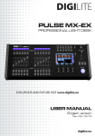
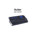
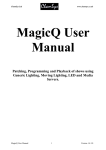
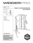
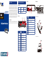
Chapter 1. Introduction
2.3 Rear Panel
Chapter 2. Physical Description and Installation
2.4 HDD Installation
Audio
2.1 Package Centents
1 x NVR
1 x Power Adapter
2 x SATA Data Cord
2 x SATA Power Cord
1 x CD-ROM
16 x Screws
2 x HDD Cradle
1 x Quick Installation Guide
USB
HDMI
VGA
HDMI
Connector
DI/DO Status LEDs
1.1 Before Installation
Network Video Recorder
Digital Out
Digital In
Alarm
CAM
1
2
3
4
1
2
3
4
USB
PWR
HDD
LAN
REC
Color
MIC IN
LAN
LAN
RESET
Reset
Description
USB
Connect your mouse and USB flash disk for local display control and backup.
Reset
Press and hold reset button to factory default.
HDMI
HDMI output
VGA
VGA output
e-SATA
External E-SATA HDD
LAN
10/100/1000Mbps network.
I/O
DI x 4 / DO x 4
Audio
Audio out / Mic in
1. Remove all screws on the box.
Event
PWR/HDD/LAN/REC/Event Status LEDs
LEDs
AUDIO OUT
eSATA
PWR
I/O
Alarm/Camera Status LEDs
USB
12V DC
2.2 Front Panel
Before installation, please be sure to read this quick installation guide and user’s manual
(CD) carefully to complete machine installation. This guide shows how to quickly set up the
NVR.
VGA
e-SATA
12V
D+
DDI 0
DI 1
DI 2
DI 3
GND
DO 0
DO 1
DO 2
DO 3
Thank you for purchasing PLANET 9/16-Ch Network Video Recorder. The Network Video
Recorder is designed for usage within a surveillance system, and performs recordings and
playbacks pictures from network cameras in the system. It is a recording device using a
hard disk drive to record camera pictures instead of using video tapes so that pictures
recorded by repeated overwriting will not experience deterioration of the recorded picture
quality. Up to 9 (NVR-915) and 16 (NVR-1615) cameras can be connected via a network and
it is possible to record their camera pictures. It is possible to perform the settings or operate
the NVR using a web browser installed on a PC connected to a network, or local display.
Recorded video can be played back from remote site by a PC. The NVR is compatible with
most major brand cameras and its ability to automatically search and find the available
cameras on the network can greatly reduce the user effort when expanding the system.
USB
Description
PWR
Green
LED on when system is ready.
HDD
Green
LED on when HDD is reading or writing.
LAN
Blue
LED blinking when network is connected.
REC
Green
LED on when record schedule is on.
Event
Green
LED on when event detection schedule is on.
Alarm
Amber
LED on when hard disk writes error.
CAM
Amber
LED on when system has camera disconnected.
Digital In (1~4)
Amber
LED on when digital input X is closed.
Digital Out (1~4)
Blue
LED on when digital output X is closed.
2. Lift up and remove the cover.
3. Assemble the hard disk cradles with the silver screws.
5. Connect the SATA data cable and power cable between hard disk and main board.
Login the Homepage
Chapter 3. Connection and Management
The Web management allows you to access and manage the Network Video Recorder
easily. Launch the Web browser and then enter the IP address. The default IP address is
192.168.0.20. And, fill out the User Name and Password to login the Web management.
The default User Name and Password are both admin.
3.1 Connection
PoE Gigabit Switch
NVR-915/NVR-1615
PoE
User PC
PoE
4. Install the hard disks in the case with the black screws.
1000Base-T UTP
6 Put the cover back.
IP Camera
IP Camera
PoE
1000Base-T UTP with PoE
3.2 Management
Utility
Installing “Planet IP Wizard II” search utility from the CD
1. Please go to Start => Programs => PLANET IP Wizard II => PLANET IP Wizard II to run
the search tool. Then you will see the utility start searching the network.
2. The NVR should be located and its IP address should be displayed: Double-click on it and
the program should automatically access the NVR’s web administration page from your
default browser.
7. Assemble all the screws back to the box.
Further configurations and information can be found in the user’s manual CD.