1
MTP40 User Manual
Rev.02
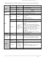
The following table sums up which parameters can be set and the related range settings.
MENU
PARAMETER
MEANING
RANGE SETTINGS
CH
GR
Channel
Group
Freq
Frequency
0 ÷ 59
0 ÷ 39 + SYNC GROUP
depends on the MTP40 Model:
1
470-640
2
566-798
depends on the mic mode setting
(ex. -40dB ÷ 40dB step of 1 dB)
Flat/60/80/120/170/250/400 Hz
’2 wires’
‘2 wires + bias’
‘3 wires’
‘2 wires & phantom’
‘2 wires + bias & phantom’
TUNING
AUDIO
High Pass Filter
Gain of the
audio signal
High Pass filter
Mode
MIC type
Phase
Audio signal
phase
AF In Gain
MIC
PTT Mode
It defines how
and what
information the
transmitter has
to send
RF POWER
RF Power
RF Power
NOISE RED.
NRSYS
Noise reduction
Led Light
OTHERS
Led Mode
Battery
Power switch
green
brightness
It defines when
the power
switch led (see
Fig. 3) has to
become RED
Battery type
0° or 180°
Disable:when the PTT button is pushed, nothing
happen. (the transmitter sends AF+Tone
squelch)
Normal: when the PTT button is pushed, the
transmitter send a different RF signal. According
to the receiver configuration the audio can be
enabled/disable on LINE (and/or COM).
Muting: the transmitter doesn’t send the audio.
The voice is cut, it doesn’t enter to the
microphone
No Data: the transmitter sends neither tone
squelch nor battery data.
High (50 mW ERP) or
Low (10 mW ERP)
ENR: Wisycom Extended-NR,noise optimized
ENC: Wisycom Extended-NC,voice optimized
0 ÷ 16
None: never
ModPeak: when audio get close to saturation
PTT: when the PTT button is pushed
Alkaline or NiMH
9