1
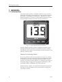
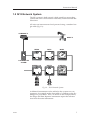
A L W A Y S
A T
T H E
F O R E F R O N T
O F
T E C H N O L O G Y
Instruction Manual
M
A
N
U
A
L
Simrad IS12
Depth Instrument
III
IS12 Depth Sounder
© 2002 Simrad Ltd
The technical data, information and illustrations contained in this publication were to the best of our knowledge correct at the time of
going to print. We reserve the right to change specifications, equipment, installation and maintenance instructions without notice as
part of our policy of continuous development and improvement.
No part of this publication may be reproduced, stored in a retrieval system or transmitted in any form, electronic or otherwise without
prior permission from Simrad Ltd.
No liability can be accepted for any inaccuracies or omissions in the publication, although every care has been taken to make it as complete and accurate as possible.
IV
E04050 Issue 1.1 11/01/02 MDL
Instruction Manual
CONTENTS
1
GENERAL
1.1 Introduction . . . . . . . . . . . . . . . . . . . . . . . . . . . . . . . . . . . . . . . 6
1.2 IS12 Network System . . . . . . . . . . . . . . . . . . . . . . . . . . . . . . . . 7
2
OPERATION
2.1 Water Depth . . . . . . . . . . . . . . . . . . . . . . . . . . . . . . . . . . . . . . . 8
2.2 Alarms . . . . . . . . . . . . . . . . . . . . . . . . . . . . . . . . . . . . . . . . . . . . 9
2.2.1 Shallow Alarm . . . . . . . . . . . . . . . . . . . . . . . . . . . . . . . 9
2.2.2 Deep Alarm . . . . . . . . . . . . . . . . . . . . . . . . . . . . . . . . . 10
2.3 Info Key . . . . . . . . . . . . . . . . . . . . . . . . . . . . . . . . . . . . . . . . . . . 11
2.4 Backlighting . . . . . . . . . . . . . . . . . . . . . . . . . . . . . . . . . . . . . . . 12
2.5 Remote Control / Alarm Option . . . . . . . . . . . . . . . . . . . . . . . 13
3
CALIBRATION
3.1 Selecting Units . . . . . . . . . . . . . . . . . . . . . . . . . . . . . . . . . . . . . 15
3.2 Damping . . . . . . . . . . . . . . . . . . . . . . . . . . . . . . . . . . . . . . . . . . 16
3.3 Offset . . . . . . . . . . . . . . . . . . . . . . . . . . . . . . . . . . . . . . . . . . . . . 17
3.3.1 Keel Offset . . . . . . . . . . . . . . . . . . . . . . . . . . . . . . . . . . 18
3.3.2 Waterline Offset . . . . . . . . . . . . . . . . . . . . . . . . . . . . . . 19
3.4 Switching Transducer Off / On . . . . . . . . . . . . . . . . . . . . . . . . 19
3.5 Local & Network Backlighting . . . . . . . . . . . . . . . . . . . . . . . . 20
3.6 Shop Mode . . . . . . . . . . . . . . . . . . . . . . . . . . . . . . . . . . . . . . . . 21
3.7 Disable Remote Control . . . . . . . . . . . . . . . . . . . . . . . . . . . . . . 21
4
INSTALLATION
4.1 Instrument Head Installation . . . . . . . . . . . . . . . . . . . . . . . . . . 22
4.1.1 Front Mounting . . . . . . . . . . . . . . . . . . . . . . . . . . . . . . 22
4.1.2 Rear Mounting . . . . . . . . . . . . . . . . . . . . . . . . . . . . . . . 24
4.2 Transducer Installation . . . . . . . . . . . . . . . . . . . . . . . . . . . . . . . 25
4.2.1 Selecting a Suitable Location . . . . . . . . . . . . . . . . . . . . 25
4.2.2 Cutting and Sealing the Hole . . . . . . . . . . . . . . . . . . . 26
4.2.3 Installing the Transducer . . . . . . . . . . . . . . . . . . . . . . . 27
4.3 Electrical Installation . . . . . . . . . . . . . . . . . . . . . . . . . . . . . . . . 28
4.4 Electronic Interference Suppression . . . . . . . . . . . . . . . . . . . . 29
5
APPENDIX
5.1
5.2
5.3
5.4
5.5
5.6
Notes on Turbulence & Signal Acquisition . . . . . . . . . . . . . . 30
Fault Finding . . . . . . . . . . . . . . . . . . . . . . . . . . . . . . . . . . . . . . . 31
Spares and Accessories . . . . . . . . . . . . . . . . . . . . . . . . . . . . . . . 31
Dimensions . . . . . . . . . . . . . . . . . . . . . . . . . . . . . . . . . . . . . . . . 32
Specification . . . . . . . . . . . . . . . . . . . . . . . . . . . . . . . . . . . . . . . 32
Service & Warranty . . . . . . . . . . . . . . . . . . . . . . . . . . . . . . . . . . 32
V
IS12 Depth Sounder
1 GENERAL
1.1 Introduction
The Simrad IS12 System is a flexible modular series of instruments that offer large, clear displays, easy to operate functions
and robust, weatherproof construction. Whether as a stand
alone instrument, or as part of a networked navigation system,
the IS12 Depth Sounder will offer superb performance.
DEPTH
DEPTH
M
LIGHT
SHALL
DEEP
INFO
Fig 1.1 - IS12 Depth Sounder Instrument
The IS12 Depth Sounder system is supplied complete with a
through hull depth transducer and all the necessary cabling.
All functions are easily accessed, thanks to IS12’s intuitive, user
friendly control system.
Thank you for choosing Simrad.
If you are pleased with your instrument we hope you will be
interested in our range of marine electronic equipment, which
is manufactured to the same high standards as IS12. Please
contact your nearest Simrad agent for a catalogue showing our
increasing range of high tech navigational instruments, GPS,
Autopilots, Radar, Fishfinders and VHF radio sets.
Simrad operate a policy of continual development and reserve
the right to alter and improve the specification of their products without notice.
6
E04050
Instruction Manual
1.2 IS12 Network System
The IS12 system is built around a high speed bus networking
system that allows instruments to be easily interconnected and
share data.
All units are interconnected and powered using a standard single cable (Fig 1.2) -
COMPASS Tx
WIND Tx
MEGA
DATA
WIND
SPEED/LOG
DEPTH
COMPASS
CONTROLLER
ALARM
Fig 1.2 - IS12 Network System
Additional instruments can be added to the system to act as
repeaters, for example at the chart table of a sailboat or the flybridge of a powerboat. Thus, as shown in the example above,
the Mega and Data Repeater instruments repeat the information from the main instruments.
E04050
7
IS12 Depth Sounder
2 OPERATION
2.1 Water Depth
On power up, the current water depth is shown (Fig 2.1) -
DEPTH
DEPTH
M
LIGHT
SHALL
DEEP
INFO
Fig 2.1 - Default Depth Display
In this example, the depth is displayed in Metres. The arrow
in the top line of the display indicates the trend (up or down).
NOTE
Refer to section 5.1 in the appendix for further information on
how the depth sounder will behave if the depth signal is lost.
As a default, the Depth Sounder will display the depth below
the transducer. An offset can be entered so that the display
shows either the depth below the keel or the waterline depth.
Refer to Section 3.3 for more details.
2.2 Alarms
The IS12 Depth Sounder features an audible alarm function
that can be set to alert if the water depth falls below or above a
specified value. This is a useful function to avoid the boat running aground in shallow water, or straying into deep water.
NOTE
The alarms will sound for 15 seconds when triggered by the
alarm condition (unless manually muted), then sound again
after a 15 second pause and continue in this pattern until the
water depth is once again within the specified parameters.
2.2.1 Shallow Alarm
The shallow alarm will sound if the water depth falls below a
specified amount, to warn if the boat is about to run aground.
8
E04050
Instruction Manual
Press the SHALL key to access the shallow alarm (Fig 2.2) -
M
LIGHT
SHALL
DEEP
INFO
DEPTH
SHALL
M
LIGHT
SHALL
DEEP
INFO
Fig 2.2 - Shallow Alarm Function
If the shallow alarm is OFF, pressing the or (SHALL or
DEEP) keys will switch on the alarm at the previously entered
value (Min 0.6m/2ft, Max 100m/327ft).
Use the or to adjust the shallow alarm setting in 0.1m or
1ft increments and press (INFO) to confirm and exit to the
main screen.
Press and hold the
10ft increments.
Press
or
keys to scroll up and down in 1m /
(LIGHT) to turn the shallow alarm off.
NOTE
While the alarm is on, the
icon will be shown on the display.
NOTE
If no key is pressed within 5 seconds, the display will exit to
the main screen and any changes will be ignored.
If the alarm sounds, press SHALL to mute.
E04050
9
IS12 Depth Sounder
2.2.2 Deep Alarm
The deep alarm will sound if the water depth goes above a
specified amount.
Press the DEEP key to access the deep alarm (Fig 2.3) -
M
LIGHT
SHALL
DEEP
INFO
DEPTH
DEEP
M
LIGHT
SHALL
DEEP
INFO
Fig 2.3 - Deep Alarm Function
If the deep alarm is OFF, pressing the or (SHALL or
DEEP) keys will switch on the alarm at the previously entered
value (Min 0.6m/2ft, Max 100m/327ft).
Use the or keys to adjust the deep alarm setting in 0.1m
or 1ft increments and press (INFO) to confirm and exit to
the main screen.
Press and hold the
/ 10ft increments.
Press
NOTE
10
and
keys to scroll up and down in 1m
(LIGHT) to turn the deep alarm off.
While the alarm is on, the
icon will be shown on the display.
E04050
Instruction Manual
NOTE
If no key is pressed within 5 seconds, the display will exit to
the main screen and any changes will be ignored.
If the alarm sounds, press DEEP to acknowledge and cancel.
NOTE
The deep alarm cannot be set lower than the shallow alarm, and
the shallow alarm cannot be set higher than then deep alarm.
2.3 Info Key
Pressing the INFO key will cycle through the information that
can be shown on the top line of the display (Fig 2.4) - Default (DEPTH)
- Shallow alarm setting
- Deep alarm setting
M
LIGHT
SHALL
DEEP
INFO
DEPTH
SH 1.5
DEPTH
DP 45.0
Fig 2.4 - Info Key Functions
The selected information will be displayed permanently on the
top line until the INFO key is pressed again.
E04050
11
IS12 Depth Sounder
2.4 Backlighting
The backlighting illuminates the display and the keys, with five
levels of brightness.
To switch the backlighting on, press the LIGHT key. The display will illuminate and the large digits will show the current
lighting level (Fig 2.5) -
LIGHT
SHALL
DEEP
INFO
DEPTH
LIGHT
LIGHT
SHALL
DEEP
INFO
Fig 2.5 - Turning Backlighting On
Four icons will be shown on the bottom line of the display, corresponding to the four keys ( , , and ) Press the
(DEEP) key to increase the brightness (max 5), (SHALL) to
decrease it (min 1), (INFO) to accept the selected brightness
or (LIGHT) to turn the backlighting off.
The currently selected lighting level will be applied if no key is
pressed after five seconds.
NOTE
While the backlighting is on, the lamp icon (
on the bottom left of the display.
) will be shown
The backlighting can either be Local or Network controlled - see
Section 3.5 for more details.
12
E04050
Instruction Manual
2.5 Remote Control / Alarm Option
The optional remote control allows all functions of each instrument to be remotely controlled. Any alarms sounded are also
repeated on this unit. See Section 3.7 regarding enabling and
disabling remote control functionality for this instrument.
As this unit is intended to control all instruments in the IS12
range, the keypad is a generic design. Fig 2.6 indicates the
respective key positions -
DEPTH
DEPTH
M
LIGHT
SHALL
DEEP
INFO
Select
Instrument
Fig 2.6 - Remote Control Key Positions
E04050
13
IS12 Depth Sounder
3 CALIBRATION
To protect the calibration functions, these are held in a hidden
menu. To enter calibration mode, press and hold the LIGHT
key (Fig 3.1) -
LIGHT
SHALL
DEEP
INFO
DEPTH
UNITS
LIGHT
SHALL
DEEP
INFO
Fig 3.1 - Entering Calibration Mode
In calibration mode, pressing the (SHALL) or (DEEP)
keys will cycle through the available calibration options - Units (Section 3.1)
- Damping (Section 3.2)
- Offset (Section 3.3)
- Transducer Off/On (Section 3.4)
- Local / Network Backlighting (Section 3.5)
- Shop Mode (Section 3.6)
- Disabling Remote Control Facility (Section 3.7)
Select the required option and press to enter. While in the
calibration options, the following key functions apply - To save settings and return to Cal menu press
- To ignore changes and return to Cal menu press
.
.
- To exit calibration mode at any time, press and hold
14
.
E04050
Instruction Manual
3.1 Selecting Units
Enter calibration mode - the display will show UNITS CAL.
Press (INFO). The depth units can then be selected (Metres
or Feet) by pressing the or keys (Fig 3.2) -
M
LIGHT
SHALL or DEEP
INFO
SHALL
INFO
FT
LIGHT
DEEP
Fig 3.2 - Selecting Depth Units
Press
NOTE
E04050
to set the selected depth units.
Press to exit to the main calibration menu without changes
being saved.
15
IS12 Depth Sounder
3.2 Damping
The Damping function adjusts the update rate of the display. A
damping level of 0 (minimum) will cause the display to update
rapidly, while a damping level of 4 (maximum) will result in a
more stable display, but one that is less frequently updated.
Enter calibration mode, press once (the display will show
DAMP CAL) and press (INFO).
The damping level can be adjusted using the
(Fig 3.3) -
and
keys
DEPTH
DAMP
LIGHT
SHALL
DEEP
INFO
Fig 3.3 - Adjusting Damping Level
To set the selected damping level, press . The display will
then return to the main calibration menu.
NOTE
16
Press
to exit to the main calibration menu at any point.
E04050
Instruction Manual
3.3 Offset
As a default, the Depth Sounder displays the water depth
between the transducer and the sea bed.
However, for boats such as sailing yachts with a keel, it is more
useful for the display to show the available water below the
keel, which is sometimes as much as 2m below the transducer.
In other circumstances it may be more important to show the
waterline depth, that is the total depth of water from the bottom to the surface.
The IS12 Depth Sounder allows a keel or waterline offset to be
entered, so that the displayed depth will more accurately
reflect the depth of water available beneath the boat.
Waterline Depth
transducer
Depth below
keel
Depth below
Keel
Offset
Waterline
Offset
To calculate the offset amount, measure the vertical distance
between the bottom of the keel and the bottom of the transducer for a keel offset, or the vertical distance between the surface
of the water and the bottom of the transducer for a waterline
offset (Fig 3.4) -
Fig 3.4 - Depth Offset
NOTE
The offset amount will be in the same units as selected in
Section 3.1.
- ctd
E04050
17
IS12 Depth Sounder
To enter the offset, enter calibration mode then press
(the display will show OFFST CAL) and press .
twice
The current offset will be displayed - default value 0.0 (Fig 3.5) -
DEPTH
OFFST
M
LIGHT
SHALL
DEEP
INFO
Fig 3.5 - Entering Offset
3.3.1 Keel Offset
Since entering a keel offset is reducing the displayed depth, this
is entered using the key - which will adjust the offset in 0.1m
/0.1ft decrements. The display will show “KEEL” (Fig 3.6) KEEL
M
LIGHT
SHALL
DEEP
INFO
Fig 3.6 - Entering Keel Offset
To set the selected keel offset, press . The display will then
return to the main calibration menu.
NOTE
18
Press
to exit to the main calibration menu at any point.
E04050
Instruction Manual
3.3.2 Waterline Offset
A waterline offset increases the displayed depth, so this is
entered using the key - this adjusts the offset in 0.1m /0.1ft
increments. The display will show “W’LN” (Fig 3.7) -
W’LN
M
LIGHT
SHALL
DEEP
INFO
Fig 3.7 - Entering Waterline Offset
To set the selected waterline offset, press . The display will
then return to the main calibration menu.
Press
NOTE
to exit to the main calibration menu at any point.
3.4 Switching Transducer Off / On
If the boat is also fitted with a fishfinder running at a similar
frequency, there may be some interference between the two
transducers. In this case, the transducer can be switched off.
This is also useful to conserve power when on a long ocean
crossing, where the depth sounder is not needed.
DEPTH
TRANS
LIGHT
SHALL
DEEP
INFO
Enter calibration mode, press
TRANS CAL) and press .
x3 (the display will show
The display will show “On”. To turn the transducer off, press
the or key (the display will show “OFF”) and press to
confirm (Fig 3.8). The display will then return to the main calibration menu.
LIGHT
SHALL
DEEP
INFO
Fig 3.8 - Switching
Transducer Off
NOTE
E04050
While the transducer is set to off, the main depth display will
show OFF.
To turn the transducer back on again repeat the above procedure.
Press
to exit to the main calibration menu at any point.
19
IS12 Depth Sounder
3.5 Local & Network Backlighting
The backlighting can be set so that any changes made are
duplicated across the system (Network), or so that any changes
are limited to this specific instrument only (Local).
NOTE
The IS12 instruments are set to Networked lighting as default.
Enter calibration mode, press four times (the display will
show LIGHT on the top line) and press (INFO).
The large digits will show the current setting - NET for
Networked or LOC for Local. The setting can be changed
using the or keys (Fig 3.9) -
LIGHT
LIGHT
SHALL
DEEP
INFO
Fig 3.9 - Changing from Network to Local Backlighting
To set the selected backlighting, press
return to the main calibration menu.
. The display will then
NOTE
Press
NOTE
Any changes will affect this specific instrument only.
20
to exit to the main calibration menu at any point.
E04050
Instruction Manual
3.6 Shop Mode
This is a simulation mode for in-store demonstration - do not
use.
3.7 Disable Remote Control
On some installations which includes the IS12 Remote Control,
it may be more convenient to limit remote control access to
only some instruments on the network - for example on a flybridge power boat with a set of instruments on both steering
stations, it would not be desirable to be able to control the
instruments on the flybridge (Fig 3.10) Flybridge
Front mounted instruments - no remote control required
Remote control disabled
Main Steering Station
Rear mounted instruments - remote control required.
Remote control enabled
Fig 3.10 - Flybridge system with Remote control of main steering
system only
To disable remote control functionality on this instrument,
enter calibration mode, press six times (the display will
show CTRL CAL on the top line) and press (INFO).
The large digits will show the current setting - ON for remote
control enabled or OFF for remote control disabled. The setting can be changed using the or keys.
To set the selected mode, press
to the main calibration menu.
. The display will then return
NOTE
Press
to exit to the main calibration menu at any point.
NOTE
Any changes will affect this specific instrument only.
For further information on Remote Control operation, please
refer to the user manual supplied with the Remote Control /
Alarm unit.
E04050
21
IS12 Depth Sounder
4 INSTALLATION
4.1 Instrument Head Installation
All IS12 instrument heads are a standard 110 x 110mm (4.3 x 4.3
in) size, and can be mounted either from the front or the rear.
4.1.1 Front Mounting
Fig 4.1 - Front Mounting
35mm (1.4 in)
minimum
Front mounting (Fig 4.1) is the standard method of fitting and
is the most straightforward. When mounting the instrument
head it is important to ensure that there is adequate clearance
behind the bulkhead for the rear of the instrument with the
cables inserted - allow at least 35mm (1.4 in) clearance (Fig 4.2).
Additionally, the instrument should not be fitted to a surface
that has a curve greater than 1mm (1⁄25 in) across the mounting
area. If fixing to an uneven surface, care should be taken not
to overtighten the screws. When choosing a location, consideration should be given to the water integrity of the gasket seal if
the surface is not flat. IS12 is designed to be weatherproof, but
the rear of the instrument case with its electrical connections
should be protected from moisture as far as possible.
Tools required for installation -
Fig 4.2 - Clearance Required
Behind Bulkhead
-Drill
- 86mm (3.4in) hole saw
- 2.5mm (0.09in) drill bit
- Countersinking bit
Using the self adhesive template supplied, drill the central
aperture for the instrument case using the hole saw, then the
four fixing holes as indicated on the template. If the instruments are to be fixed to a GRP bulkhead, the fixing holes
should be countersunk after drilling, to stop the screws splitting the gelcoat.
ctd -
22
E04050
Instruction Manual
The instrument is 110mm (4.33 in) square, but a distance of at
least 6mm (0.25 in) should be allowed between adjacent units
for the protective instrument cover supplied.
NOTE
Long term exposure to direct sunlight can damage the liquid
crystal display if left unprotected when not in use - always use
the instrument cover supplied.
The easiest way to fit the keypad and the bezel to the installed
instrument head is to locate the keypad in the keyholes in the
bezel and then offer this up to the instrument head, angling the
bezel back slightly to prevent the keypad falling out. The bezel
should click into place when located correctly (Fig 4.3) -
Fig 4.3 - Fitting Keypad and Bezel
To remove the bezel, simply lift the top edge of the bezel
slightly to disengage the locking clips and pull away from the
instrument head (Fig 4.4) -
Fig 4.4 - Removing Bezel
E04050
23
IS12 Depth Sounder
4.1.2 Rear Mounting
When the instrument is rear mounted, only the display can be
seen - the main body of the instrument, including the keypad is
hidden behind the panel. This is a more elegant method of
installation, but does require precise cutting of the apertures into
the bulkhead or dashboard. Therefore, it is recommended that
installation is done by a professional marine installer.
The instrument can be fixed to the panel using either the self
tapping screws supplied (if the panel is thick enough), or using
2mm studs fixed to the rear of the panel which align with the
four fixing holes (Fig 4.5).
Tools required for installation - Drill
- 5mm (0.2in) drill bit
- Fretsaw
- A fine toothed file.
To assist in cutting a precise aperture for the display, a self
adhesive template is supplied with the unit (Fig 4.6) -
Fig 4.5 - Rear Mounting
Cut on
waste side
of template
Fig 4.6 - Cutting Aperture
Fix the template in the correct position and drill four 5mm
holes on the waste side of the four corners of the aperture.
Starting from one of these holes, carefully cut along the dotted
line around the four edges. To ensure the hole is a good fit, cut
slightly inside the line (on the waste side) and then use the file
to smooth the edges until the display fits precisely.
NOTE
24
Because the keypad is not accessible with this method of mounting, the Remote Control unit (see Section 2.9) will be required
to enable control of instrument functions.
E04050
Instruction Manual
4.2 Transducer Installation
The IS12 Depth Sounder is supplied with a 50mm (2in) diameter plastic depth sensor, or transducer.
WARNING
Plastic transducers are suitable for GRP, ferrous, ferrocement or
wooden ply hulled boats. They are not suitable for boats with
a solid, planked wooden hull as swelling can damage the transducers. For this application, a bronze transducer will be necessary - contact your local Simrad agent for more details.
WARNING
As transducer installation involves drilling a hole in the bottom
of the boat, please read these installation instructions thoroughly before attempting installation. If in doubt, employ a qualified marine electronics engineer to install the transducer.
NOTE
Simrad cannot accept any responsibility for the cost of hauling the boat out of the water in the event of the transducer not
functioning - it is recommended that the transducer is tested by
connecting it to the powered instrument and lowering it over
the side of the boat into the water. Check that the depth reading given is accurate before proceeding with haul out.
4.2.1 Selecting a Suitable Location
For optimum performance, the transducer must be located in a
position that is clear from any turbulence caused by hull protrusions, keels, skin fittings etc (Fig 4.7) Sailboat
Planing Vessel
Displacement Vessel
Fig 4.7 - Suitable Location For Transducer
E04050
25
IS12 Depth Sounder
NOTE
Fairing block
Hull
For the Depth Sounder to be accurate, the transducer must be
as near vertical as possible. If the hull is angled in the selected
position, it may be necessary to use a fairing block cut to the
correct angle so that the transducer is vertical when fitted (Fig
4.8). The fairing block should be glued to the inside and outside of the hull using marine grade sealant and allowed to set
completely before proceeding.
4.2.2 Cutting and Sealing the Hole
Fig 4.8 - Using a Fairing Block
Equipment required - Drill
- Small (eg 5mm / 0.2 in) drill bit
- 50mm (2.0in) hole saw
- Marine grade silicone sealant (eg Sikaflex)
- Fibre glass resin
- White spirit
Before drilling the hole, check the area selected is as dry as possible both inside and out.
First, drill a pilot hole in the selected position - a small hole is
much easier to repair if there is a problem with the location.
Once satisfied with the location, cut a 50mm (2.0in) hole using
the hole saw, ensuring it is kept vertical (see note above)
NOTE
If replacing an existing transducer, remove all old sealant and
check the hole for any damage around the edges, which may
need to be repaired. If the existing hole is larger than 50mm
(2.0in) then this will need to be professionally repaired and it
will be necessary to select an alternative location for the new
transducer. If the hole is too small for the new transducer, the
best way to drill a larger hole is to drive a wooden block into
the existing hole and use this to locate the guide bit of the hole
saw (Fig 4.9). This will prevent the hole saw slipping.
Drill here
Wooden block
New hole diameter
Fig 4.9 - Enlarging an existing transducer hole
The hole must then be sealed - this is especially important with
GRP or sandwich foam hulled boats to avoid osmosis damage.
Ensure the hole and surrounding area is clean and dry - a hot
air gun is a useful tool to use here.
26
E04050
Instruction Manual
Apply a coating of fibreglass resin to the inside edge of the
hole, making sure all the raw edges are thoroughly sealed.
This will prevent water seeping into the hull layers causing
osmosis or delamination.
4.2.3 Installing the Depth Transducer
Remove the large plastic nut from the transducer and uncoil the
cable. Feed the cable through the hole from the outside of the
boat and then pass it through the nut. Ensure the nut is the right
way round..
Apply a generous amount of silicone sealant to the inside of the
transducer flange, then offer it up to the hole from the underneath of the boat (Fig 4.10A) -
A
B
C
Fig 4.10 - Installing the Depth Transducer
From the inside of the boat, apply more silicone sealant around
the transducer where it meets the hull (Fig 4.10B). Again, be
liberal in application - any excess can always be removed.
Replace the transducer nut and tighten down as hard as possible by hand (Fig 4.10C).
WARNING
Take care if using a wrench to tighten the nut - overtightening
could cause it to break. Normally hand tight is sufficient.
Check the installation both inside and out. Remove any excess
sealant using white spirit, making sure that there are no gaps
in the sealant around the transducer. Refer to the instructions
supplied with the sealant for curing times - allow sufficient
time for the sealant to set completely before proceeding.
When the sealant is set, recheck the seal integrity around the
transducer. The outside face of the transducer can be carefully
painted with antifouling to protect it, but check the instructions of the antifouling to ensure that it is not solvent based, as
this could damage the transducer.
E04050
27
IS12 Depth Sounder
4.3 Electrical Installation
IS12 instruments are ‘daisy chained’ together, with each instrument linking to the previous one by a single cable carrying
power and data (Fig 4.11). The cable plugs into either of the
two circular network ports on the rear of the instrument.
Fig 4.11 - IS12 “Daisychain” Cable System
The cable connectors are keyed so that they will always be correctly oriented when inserting the cable into the instrument the flattened edge of the connector should be facing down
when inserting (Fig 4.12) -
Network Bus Ports
Flattened edge
Fig 4.12 - Rear Connections
Connect the power cable to the boat’s 12v DC supply via a 3
Amp breaker or fuse as follows Red wire Black wire NOTE
28
12v DC
0v
Only one power cable is required in an IS12 system, but power
must be supplied via the correct power cable (with a red connector end), or the system will not function. Due to its higher
power consumption, it is recommended that the power cable is always
plugged into the Depth instrument if part of a network system.
E04050
Instruction Manual
A three way joiner (part no. SDJ) is available as a separate
accessory (Fig 4.13) -
Three Way Joiner SDJ
Fig 4.13 - Three way joiner
Fold wire
end back
Ensure bare wires
are not visible
Fig 4.14 - Crimp Terminals
The Transducer is connected to the instrument via crimp terminals. To ensure a good connection when fitting the terminals
to the Transducer cable, fold back the exposed wires over the
insulation before inserting into the terminal (Fig 4.14). Use a
good quality crimp tool to crimp the terminals.
The screen wire should be crimped into the same terminal as
the black (BK) wire.
NOTE
The transducer wires are colour coded and correspond to the
clearly marked terminals on the rear of the instrument (Fig
4.15) -
BK Black
+screen
BU Blue
Fig 4.15 - Transducer Connections
4.4 Electronic Interference Suppression
IS12 has been designed to minimise the effects of interference
generated by the engine alternator. However, precautions
should still be taken by routing the cables away from the
engine compartment. Do not run the cables down trunking
carrying high current cables. The transducer cable should also
be kept separate from the boat’s radio antenna cable.
Engines with spark ignition, also some refrigerators should be
fitted with suppressors. Your local agent should be able to
advise on this and supply suppression kits where necessary.
E04050
29
IS12 Depth Sounder
5 APPENDIX
5.1 Notes on Turbulence & Signal Acquisition
Normally the depth displayed will be extremely accurate, however there are certain circumstances where the accuracy of the
signal can be adversely affected. If the boat is crossing the
wake of a large vessel, the turbulence caused by the vessel’s
passage will create air bubbles which could interfere with the
depth sounder signal (Fig 5.1). As this is due to the quality of
the water, the depth instrument cannot compensate for this, but
will attempt to re-acquire an accurate signal.
Depth pulse is reflected by the
air bubbles, not the sea bed
Fig 5.1 - Turbulence caused by vessel wake
If this occurs, the depth pulse will likely be reflected off the air
bubbles rather than the sea bed, in which case the depth will
appear to drop rapidly to as little as 0.6m, which may cause the
shallow alarm to sound (if it has been set). However, after several seconds the depth instrument will work out that the signals it is receiving are not accurate.
DEPTH
DEPTH
M
LIGHT
SHALL
DEEP
Upon loss of signal, the depth instrument will display the following sequence, indicating the depth displayed is not current -
INFO
Fig 5.2 - Depth signal lost
1. The last depth reading will be held for approx 15 secs
2. The display will then flash the last depth reading for
approximately one minute
3. The display will then show dashes (Fig 5.2)
The display will show dashes until re-acquisition of signal.
30
E04050
Instruction Manual
5.2 Fault Finding
Symptom
Possible Cause
Remedy
No display on any heads • Faulty connection to power
in the system
• Fuse has blown
• Check power connection
• Replace fuse and check
power supply current
No display on one or
more heads in system
• IS12 data cable loose or broken
• Check cable linked to
first faulty unit. Replace if
necessary
Occasional poor
performance
• Electrical interference from other
• Fit interference suppressors
equipment on boat (see Section 4.4) to equipment responsible
Display shows “---”
• Faulty connection to transducer
• Check transducer connection
These simple checks should be carried out before seeking technical assistance and may save time and expense. Before contacting your servicing agent please note the unit’s serial number.
5.3 Spares & Accessories
The following spares and accessories are available from local
Simrad agents. Please quote part number when ordering IS12Mega:R
Digital Repeater
IS12Remote:F Remote Controller
E04050
SPC2M
Power Cable 2m
SDC0.3M
IS12 Cable 0.3m
SDC02M
IS12 Cable 2m
SDC05M
IS12 Cable 5m
SDC10M
IS12 Cable 10m
SDJ
Three Way Cable Joiner
IS12TD
Spare Depth Transducer
PIC
Spare Instrument Cover
ISPK02
Spare Bezel & Keypad Pack - Depth
31
IS12 Depth Sounder
5.4 Dimensions
89mm (3.5in)
110mm (4.3in)
50mm (2.0in)
20mm
(0.78in)
17mm
(0.67in)
75mm (3.0in)
110mm (4.3in)
5.5 Specification
Supply Voltage
12v (9-16v) DC
Current Consumption
Light Off - 40mA
Transducer Frequency
200kHz
Sounding Range
0.6 - 100m (2 - 328ft)
Max Resolution
0.1m / 1ft
Max units per system
32
Ambient Temp Range
-10ºC to +55ºC (14ºF to 140ºF)
Light On - 60mA
5.6 Service & Warranty
Your equipment should seldom need servicing, although it will
benefit from an application of silicone or Teflon grease to the
contacts each season.
The unit is guaranteed for 2 years from date of retail sale. If it is
necessary to have the unit repaired, return it carriage prepaid to
the agent in the country of purchase with a copy of the receipted
invoice showing the date of purchase. Where possible, return
all the components unless you are certain that you have located
the source of the fault. If the original box is not available, ensure
that it is well cushioned in packing; the rigours of freight handling can be very different from the loads encountered in the
marine environment for which the unit is designed.
For Worldwide Warranty details, please refer to the Warranty
Card supplied with this unit.
32
E04050
www.simrad.com
A L W A Y S
A T
T H E
F O R E F R O N T
O F
T E C H N O L O G Y