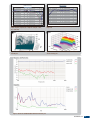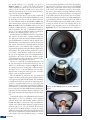
1
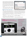
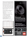
V O L U M E 2 5 , I S S U E 1 N O V E M B E R 2 0 1 1 IN THIS ISSUE 1 INDUSTRY NEWS AND DEVELOPMENTS By Vance Dickason 9 SPOTLIGHT Subwoofer Alignment with Full-Range System YEARS By Charlie Hughes 16 ACOUSTIC PATENTS By James Croft 20 TEST BENCH 29 INDUSTRY WATCH 31 Products & Services Index 5 CELEBRATING New Linear X Amplifier Filter & Attenuator, p. 8 A New Tweeter and a New Woofer from SB Acoustics By Vance Dickason Soft Dome Tweeter on the Test Bench, p. 20 Industry News and Developments By Vance Dickason Happy 25th Anniversary Voice Coil: A Quarter Century of Loudspeaker Technology! November 2011 marks the beginning of Voice Coil’s 25th year as an information resource for the loudspeaker industry. Voice Coil magazine started with a conversation between Ed Dell and me following the Audio Amateur, Inc. publication of the 3rd edition of the Loudspeaker Design Cookbook. Ed related to me a concept of creating a publication that would become an information “super highway” for the loudspeaker industry. Needless to say, I considered it not only an outstanding concept for a new publication, but something I felt the industry badly needed and would happily support. Obviously, after 25 years, we were both correct in moving forward with the publication. Mr. Dell came up with the name, Voice Coil, and as they say, the rest is history. From the first issue in November 1987 until June of 1995, Voice Coil was a monthly subscription-based, black-and-white, four-page newsletter that was written entirely by me, with no other contributors and no advertising. However, the June 1995 issue jumped to 20 pages (we are currently about 32 to 48 pages each month!) of four-color printing on gloss paper and became advertiser-driven with no subscription fee. As we head into the era of digital delivery, Voice Coil just this year became available as an Internet-delivered subscription. Besides the change in printing, distribution, and digital delivery, Voice Coil began to include other contributors such as Wolfgang Klippel, Steve Temme, Jim Croft, Mike Klasco, Pat Turnmire, Charlie Hughes, Steve Mowry, and many others over the years. Support has come not only from some of the industries finest engineers, but by the generosity of analyzer/ software manufacturers Klippel GmbH, LinearX, and Listen, Inc., who have supplied Voice Coil with some of the best test equipment available. As this loudspeaker industry magazine has grown and matured, Voice Coil continues to be what its originator and former publisher Ed Dell conceived it to be, a world-class clearing-house of information for loudspeaker engineers, manufacturers, marketing specialists, and OEM suppliers. Evidenced by the participation of writers, advertisers, and readers, Voice Coil continues to be well-received by the entire loudspeaker industry. Each year has brought increased circulation as more engineers, technicians, purchasing agents, and marketing experts discover what we have to offer. On behalf of myself, Vance Dickason, editor, Hugo Van haecke, publisher, C. J. Abate, editorial coordinator, Shannon Becker, editorial assistant, and all of the new staff at Audio Amateur who make this publication possible, we would like to thank all our readers and advertisers for their continued enthusiasm and support. Last, and certainly not least, I would like to add a special “thank you” to Edward T. Dell, for his vision and guidance that made this publication possible. It was a great idea, Ed! Download Dr. Sean Olive’s Harman Listening Test “How to Listen” is a desktop software application developed by the Harman International R&D group for the purpose of training and selecting listeners used in audio product research, development, and testing. The software consists of a number of training exercises where different kinds of timbral, spatial, and dynamic distortions commonly found within the recording and audio chains are simulated and added to music. The listener’s task is to identify, classify, or rate these distortions according to a number of well-defined perceptual attributes and scales. The software automatically adjusts the difficulty of each training task based on the listener’s Figure 1: Band Identification illustrating peaks, dips, peaks and dips, low- and high-pass filters performance. Harman is offering a free beta version of this software to audio enthusiasts in the hope that they will use it to improve their critical listening skills and appreciation for high-quality sound reproduction. Features include support for two-channel stereo and multichannel wav files (up to 24 bit, 96 kHz), includes Session and Practice modes, and currently supports two training tasks (more will be added in the next release) that include the following: t#BOE*EFOUJGJDBUJPOQFBLTEJQTQFBLTBOEEJQTMPXBOE high-pass filters (see Figure 1) t"UUSJCVUFUBTLCSJHIUEVMMGVMMUIJODPMPSBUJPO reverberation, noisy/noise-free, hum/hum-free, FX100 Audio Analyzer offers proven PureSound™speaker testing technology t Proven PureSound™ technology For the most reliable detection of different defect types. Supports defects testing across all installed analyzer channels. t Modular Analyzer architecture Customize your speaker test system by choosing the number of analysis channels, built-in impedance and DCresistance measurements, switchers etc. t Cost efficiency System costs are controlled with modular configurations matched to specific applications. t Maximum test speed Very fast glide sweep technology measures all quality parameters from a single stimulus within a fraction of a second. t FX-Control software Powerful and complete system control suite supports flexible GUI designs, built-in limits handling and sequenced measurements. NTi Audio AG Liechtenstein +423 239 6060 [email protected] 2 VOICE COIL NTI Americas Inc. Portland, Oregon, USA +1 503 684 7050 [email protected] NTI China Suzhou, Beijing, Shenzhen +86 512 6802 0075 [email protected] NTI Japan Tokyo, Japan +81 3 3634 6110 [email protected] www.nti-audio.com left/right balance (stereo mode), front/rear balance (surround mode) To download a free copy of “How to Listen” software and user manual, visit the website at www.harmanhowtolisten. blogspot.com. Call for Applications: AES Executive Director The Audio Engineering Society, Inc. (AES) is seeking applications for the position of executive director; employment will begin on January 1, 2012. The AES is the only professional society devoted exclusively to audio technology. Founded in the United States in 1948, the AES has grown to become an international organization with the purpose of: uniting persons performing professional services in the audio engineering field and its allied arts; collecting, collating, and disseminating scientific knowledge in the field of audio engineering and its allied arts: advancing such science in both theoretical and practical applications; and preparing, publishing, and distributing literature and periodicals relative to the foregoing purposes and policies. Currently, over 14,000 members are affiliated with more than 75 AES professional sections and more than 95 AES student sections around the world. The AES also serves the educational needs of its members and the audio industry at-large through international technical meetings, equipment exhibitions, and a wide range of publications. Conventions, which include scientific presentations, student activities, workshops, and exhibitions, are held annually both in the United States and Europe. Additional conferences and regional summits are held periodically throughout Latin America, Asia, Europe, and North America. Capsule Job Description of the Executive Director: The executive director (ED) facilitates the operational activities of the AES and serves as the Society’s chief operating officer. The ED is responsible to the AES Board of Governors and its Executive Committee, which provide overall policy guidance and operational oversight. The ED provides leadership and performs such duties as required for AES to refine and successfully meet its strategic objectives, and successfully conduct operations in accordance with its educational and scientific purpose. The headquarters office of the AES is in New York City, N.Y. Publisher - Hugo Van haecke Editor - Vance Dickason (E-mail [email protected]) Voice Coil, (ISSN 1521-091X), the Periodical of the Loudspeaker Industry, is published monthly by Segment, LLC, 4 Park St., Vernon, CT 06066 USA, (860) 875-2199, FAX (860) 871-0411. Periodical rates paid at Vernon, CT and additional offices. Copyright 2011 by Segment, LLC. All rights reserved. Quotation from Voice Coil is forbidden without written permission of the publisher. 4 VOICE COIL C. J. Abate.................Editorial Coordinator Shannon Becker ..............Editorial Assistant Shannon Barraclough ....Marketing Director KC Prescott ...................................Graphics Jeff Yanco ....................................Controller Debbie Lavoie ..................Customer Service Valerie Luster.....Administrative Coordinator Submissions Send all press releases and information to Voice Coil, Segment, LLC Editorial Dept., 4 Park St., Vernon, CT 06066, or FAX us material at (860) 871-0411, or e-mail [email protected]. and the ED is required to conduct the business of the Society at this office. The ED shall devote best efforts, attention, and energies to the business of the Society, and during the term of employment, may not engage in any other business or occupation which conflicts with this obligation without prior specific written consent of the Board of Governors. Qualifications for Executive Director Applicants: t1SFWJPVTTVDDFTTGVMFYFDVUJWFMFBEFSTIJQFYQFSJFODFJO diverse and decentralized global not-for-profit associations t4USPOHCVUGMFYJCMFLOPXMFEHFCBTFEMFBEFSTIJQRVBMJUJFTBOE the ability to operate in a constantly changing environment t4VGGJDJFOUIJHIMFWFMNBOBHFNFOUFYQFSJFODFQSFGFSBCMZ including professional association experience t"QSPWFOUSBDLSFDPSEJOTVDDFTTGVMMZEFBMJOHXJUIDPNQMFY issues and relationships, including leadership styles that successfully meet diverse situations t5IFWJTJPOUPBOUJDJQBUFUIFGVUVSFOFFETPGUIF"&4BOE the ability to recommend and initiate productive actions to meet those needs, including organizational change t"CBDIFMPSTEFHSFFPSIJHIFSGSPNBOBDDSFEJUFE institution, preferably in engineering or a related field t"DPNNJUNFOUUPQSFTFSWJOHBOEFOIBODJOH"&4T technical base; further, possessing a high level of comfort with both existing and emerging audio-related technology as well as the ability to work with volunteers and staff to meet the technological needs of AES’s membership t5IFTUBUVSFUPBTTVNFBMFBEFSTIJQSPMFJOUIFQSPGFTTJPOBM engineering community, (i.e., with other professional technical societies, the National Academy of Engineering, the National Science Foundation, the Acoustical Society of America, the Institute of Electrical and the Electronic Engineers, etc., and their international counterparts) t"DPNNJUNFOUUPQSFTFSWFUIFDPMMFHJBMOBUVSFPGB volunteer professional society that continues to take pride in operating as a volunteer-staff patnership t5IFBCJMJUZUPSFDSVJUBOEFNQPXFSDBQBCMFTUBGGUPXPSL productively with the volunteers to meet the goals and objectives of AES t8FMMEFWFMPQFEDPNNVOJDBUJPOTLJMMTBOEUIFBCJMJUZUP listen, to act, and to stand behind decisions t"CJMJUZUPSFDPHOJ[FBOEFGGFDUJWFMZEFBMXJUI"&4T increasing global and multicultural responsibilities while ADVERTISING For advertising reservations contact: Strategic Media Marketing, Inc., 2 Main St., Gloucester, MA 01930 USA, Phone: (978) 281-7708, or Fax: 603-924-9467, Toll-free (800) 454-3741, e-mail [email protected]. E-mail Erica Fienman with artwork inquiries at: [email protected]. Qualified subscriptions to Voice Coil run for one year. Renew annually on-line at voicecoilmagazine.com/vcqual.html Subscriptions to Voice Coil are available in printed and digital versions. To subscribe to the digital version, please visit our website at www.audioXpress.com and complete a qualification form. When you qualify, you will receive an e-mail confirming your subscription. The current issue of each digital Voice Coil will be posted to www. gotomyvoicecoil.com at the end of the month. To access, use the link in the e-mail notification, or you can simply log in to the website to view your issue along with the archived issues. For questions relating to the digital issue, please go to the help page at www.audioxpress.com/digital_issue_help.htm. For those overseas, the cost of a printed subscription is $150.00 per year. Please contact customer service or order your subscription online at www.audioXpress.com. remaining alert for new worldwide opportunities t$BQBCJMJUZUPNBOBHFUIFGJOBODJBMBGGBJSTPGUIF4PDJFUZBOE TVTUBJO"&4WJBCJMJUZ t$PNQVUFSMJUFSBDZBOEBCVTJOFTTLOPXMFEHF t5IFBCJMJUZGPSGSFRVFOUUSBWFMOBUJPOBMBOEHMPCBMJO TVQQPSUPG"&4PCKFDUJWFTBOEFYUFSOBMBMMJBODFT "MM TVCNJTTJPOT NVTU CF TVCNJUUFE POMJOF BU XXXBFTPSH "OZRVFTUJPOTNBZCFBEESFTTFEUPi&%TFBSDI!BFTPSHw ALMA 2012 Symposium: The Future of Loudspeakers "-."UIF*OUFSOBUJPOBM-PVETQFBLFS"TTPDJBUJPO8JOUFS 4ZNQPTJVNQSPHSBNi5IF'VUVSFPG-PVETQFBLFSTwXJMMDPOWFOFPOEJGGFSFOUEBUFTJO*UCFHJOTPOUIFMBTUEBZPG UIF$&4JO-BT7FHBT5IFTZNQPTJVNMBTUTUXPEBZT'SJEBZ +BOVBSZBOE4BUVSEBZ+BOVBSZ*UXJMMBMTPCFIFMEJOB OFXMPDBUJPO5IF3JWJFSB)PUFM 5IF4ZNQPTJVNXIJDIJTUIFMBSHFTUFWFOUIFMEJOUIFXPSME FOUJSFMZ EFEJDBUFE UP UIF MPVETQFBLFS JOEVTUSZ XJMM GFBUVSF USBJOJOHDPVSTFTDPWFSJOHWBSJPVTBTQFDUTPGMPVETQFBLFSNPEFMJOHUFTUBOENFBTVSFNFOUBOENBOVGBDUVSJOH*OBEEJUJPO UIFSF XJMM CF UFDIOJDBM QBQFS QSFTFOUBUJPOT UVUPSJBM TFTTJPOT SPVOEUBCMFBOEQBOFMEJTDVTTJPOTBOFYIJCJUIBMMTIPXDBTJOH TVQQMJFSTUPUIFJOEVTUSZBOEQMFOUJGVMOFUXPSLJOHPQQPSUVOJUJFT %S 'MPZE 5PPMF XJMM QSFTFOU B GVMMEBZ USBJOJOH TFTTJPO i-PVETQFBLFSTBOE3PPNT%FTJHOJOH-JTUFOJOH&YQFSJFODFTw CBTFE PO IJT SFDFOUMZQVCMJTIFE CPPL Sound Reproduction 5IJTTFTTJPOFYQMPSFTMPVETQFBLFSBOEJOSPPNNFBTVSFNFOUT BOEUIFJSJOUFSQSFUBUJPOJOUFSNTPGMJTUFOFSQFSDFQUJPO5IFSF BSF NBOZ PQQPSUVOJUJFT GPS BOJNBUFE EJTDVTTJPO XIJDI UIF QSFTFOUFSXFMDPNFT )BMGEBZUSBJOJOHTXJMMGFBUVSFi"DUJWF/PJTF$BODFMMBUJPO 4QFDJBM $POTJEFSBUJPOT GPS -PVETQFBLFST BOE .JDSPQIPOFTw CZ .JLF ,MBTDP PG .FOMP 4DJFOUJGJD BOE i$POF 7JCSBUJPO BOE4PVOE3BEJBUJPOwCZ%S8PMGHBOH,MJQQFM 5IJT ZFBST QBOFM EJTDVTTJPO UPQJD XJMM CF i/FPEZNJVN $PQJOH XJUI UIF $POTFRVFODFT PG 4VQQMZ BOE %FNBOE &MBTUJDJUZw 1BOFM DIBJSNBO 4QJSP *SBDMJBOPT PG )BSNBO *OUFSOBUJPOBM XJMM DPOUJOVF UIJT EJTDVTTJPO CFHVO BU UIF *OUFSOBUJPOBM"&45IFVTFPGOFPEZNJVNJSPOCPSPONBHOFUTIBTCFFOJODSFBTJOHPWFSUIFMBTUGFXEFDBEFTUPBEESFTT 6 VOICE COIL UIF EFNBOET PG DPNQBDU IJHIFOFSHZ NPUPS BQQMJDBUJPOT -PVETQFBLFSTIBWFCFFOBEBQUJOHUIFiTVQFSNBHOFUTwUPEFMJDBUFMZCBMBODFUIFTJ[FQFSGPSNBODFSBUJPEFNBOETJOUPEBZT NBSLFUQMBDF*OSFDFOUNPOUITUIFBWBJMBCJMJUZPGOFPEZNJVN IBTCFFOTISJOLJOHXIJMFUIFDPTUPGUIFNBHOFUTXIJDIVTF UIF SBSF FBSUI FMFNFOU IBT TLZSPDLFUFE5IF XPSLTIPQ XJMM TFSWF BT B GPSVN GPS JOEVTUSZ QSPGFTTJPOBMT GSPN BMM BTQFDUT PGUIFWBMVFDIBJOUPDPMMFDUJWFMZEJTDVTTBOECFHJOUPBEESFTT UIF GBDUT BOE NZUIT TVSSPVOEJOH UIF HMPCBM JTTVF XIJDI IBT DBVTFETJHOJGJDBOUQBSBEJHNTIJGUTJOUIFXBZXFUIJOLBCPVU UIFGVUVSFPGUIFJOEVTUSZ 5IF"-."8JOUFS4ZNQPTJVNXJMMPWFSMBQBOEQBSBMMFMUIF *OUFSOBUJPOBM$POGFSFODFPO$POTVNFS&MFDUSPOJDT*$$& QSFTFOUFECZUIF*&&&$POTVNFS&MFDUSPOJDT4PDJFUZ*UXJMM UBLFQMBDF+BOVBSZoXJUIJOUIF/PSUI)BMMPGUIF-BT 7FHBT$POWFOUJPO$FOUFSBOFBTZDPNNVUFUP5IF3JWJFSB 5IF "-." #PBSE PG %JSFDUPST JO DPOTJEFSBUJPO PG UIF QSPHSBNUIFNFSFMBUJOHUPUIFGVUVSFPGMPVETQFBLFST IBWF DPNNJUUFEUPGBDJMJUBUJOHPQQPSUVOJUJFTGPSLOPXMFEHFTIBSJOH CZQBSBMMFMJOHUIFUXPQSPHSBNTBOENPWJOHUPUIJTOFXMPDBUJPO5IF*$$&JTXIFSFLFZUFDIOPMPHJFTQSPEVDUTTFSWJDFT BOE BSDIJUFDUVSFT GPS DPOTVNFS FOUFSUBJONFOU BOE JOGPSNBUJPO EFMJWFSZ BSF GJSTU QSFTFOUFE TFF XXXJDDFPSH GPS NPSF JOGPSNBUJPO 5IF "-." 8JOUFS TZNQPTJVN XJMM BUUSBDU WJTJUPST BOEBUUFOEFFTGSPNBSPVOEUIFXPSMEBOEJTBHSFBUPQQPSUVOJUZGPSNBOVGBDUVSFSTPGDPNQPOFOUTNBUFSJBMTUFTUFRVJQNFOUBOETFSWJDFTUPUIFJOEVTUSZUPFYIJCJUUIFMBUFTUQSPEVDUT UPUIFJOEVTUSZ*UJTBMTPBHSFBUPQQPSUVOJUZGPSMPVETQFBLFS 0&.T UP NFFU XJUI TFOJPS FOHJOFFST BOE EFDJTJPONBLFST GSPN 6OJUFE 4UBUFT MPVETQFBLFS DPNQBOJFT XIP XJMM CF BUUFOEJOHUIFTIPX"-."JTIBQQZUPJTTVFJOWJUBUJPOTUP FYIJCJUPST BOE WJTJUPST GSPN PWFSTFBT BOE BTTJTU BUUFOEFFT XJUI PCUBJOJOH B WJTB )PUFM SPPNT BSF CMPDLFE BU 5IF 3JWJFSB VOEFS UIF $&4 GSPN +BOVBSZ o BOE VOEFS "-." *OUFSOBUJPOBM GSPN +BOVBSZ o 'PS NPSF JOGPSNBUJPOWJTJUUIF"-."*OUFSOBUJPOBMXFCTJUFBUXXX BMNBJOUFSOBUJPOBMPSH Linear X LF280 Precision Amplifier Filter & Attenuator 5IF NFBTVSFNFOU PG $MBTT % BOE PUIFS 18. PS %FMUB 4JHNBEJHJUBMNPEVMBUPSUZQFPVUQVUTUBHFBNQMJGJFSTTVDIBT BUZQJDBMTVCXPPGFSBNQMJGJFS PGUFOQSFTFOUTBQSPCMFNEVFUP IJHIGSFRVFODZTXJUDIJOHOPJTFDPNQPOFOUT5IFTFIJHIGSFRVFODZDPNQPOFOUTDBOPCTUSVDUUIFNFBTVSFNFOUPGJOCBOE UZQJDBMoL)[NFBTVSFNFOUT.BOZPGUIFTFBNQMJGJFST IBWFMJNJUFEIJHIGSFRVFODZGJMUFSJOHPGUIFJSPXOBOENBOZ BOBMZ[FSTPSPUIFSNFBTVSJOHJOTUSVNFOUBUJPOIBWFJOBEFRVBUF GJMUFSJOHUPSFNPWFUIFQBTTCBOEFGGFDUTPGUIFTFTUSPOHIJHI GSFRVFODZ PVUPGCBOE DPNQPOFOUT 5IF -' PGGFST B TUFFQL)[UIPSEFSQBTTJWFMPXQBTTGJMUFSTFFFigure 2 UP SFNPWF UIFTF VOXBOUFE IJHIGSFRVFODZ DPNQPOFOUT BOE FOBCMFBDDVSBUFJOCBOEBNQMJGJFSSFTQPOTFNFBTVSFNFOUT 5IF -' JT DPOTUSVDUFE FOUJSFMZ PG .PMZ 1FSNBMMPZ 1PXEFS .11 UPSPJE JOEVDUPST BOE 1PMZQSPQZMFOF DBQBDJUPSTGPSUIFVMUJNBUFJOTUBCJMJUZIJHIGSFRVFODZQFSGPSNBODF SFEVDUJPOPGIJHIGSFRVFODZMPTTBOENBYJNVNMJOFBSJUZTFF Photo 1 5IF -' VUJMJ[FT B DPNCJOBUJPO PG JEFOUJDBM Where the next big thing meets the light of day. Somewhere a back room conversation has caused a burst of inspiration. And it will be unveiled here. Come see a bright idea light the way to tomorrow. Tuesday, January 10 – Friday, January 13, 2012 Las Vegas, Nevada | CESweb.org REGISTER NOW components to reduce component sensitivity and produce a highly stable response with maximum passband flatness. A common problem with any passive filter is loading by the external cable capacitance or analyzer/meter input circuitry which can alter the response. The LF280 provides a precision R2R ladder attenuator, which largely removes the effects of external device loading, and provides a constant low output impedance regardless of the attenuation selected. For attenuation levels of –6 dB, –12 dB, or lower, the effects of any external device loading are effectively eliminated. An additional advantage of the precision attenuator is to reduce signal levels fed to other measuring devices which may not be capable of handling the very large signals produced from high-power amplifiers. Features include: t%VBMQSFDJTJPOQBTTJWFth order 80-kHz, low-pass filters t%VBMQSFDJTJPOE#BUUFOVBUPSTXJUIE#TUFQT t%VBMDIBOOFMTJOHMFFOEFEPSNPOPCSJEHFE differential mode t)JHIQPXFSDBQBCJMJUZ73.4DIBOOFMPS 73.4CSJEHFE t7FSZGMBUQBTTCBOESFTQPOTFE#UPL)[ t7FSZIJHITUPQCBOESFTQPOTFE#BCPWFL)[ t7FSZIJHIMJOFBSJUZBUIJHITJHOBMMFWFMT t-PXTFOTJUJWJUZUPDBCMFBOBMZ[FSMPBEJOH t$POTUBOUPVUQVUJNQFEBODFlj$I t%VBMGJWFXBZCJOEJOHQPTUBNQMJGJFSDPOOFDUPST t%VBM#/$BOE9-3PVUQVUTJHOBMDPOOFDUPST t4IPSUDJSDVJUPVUQVUQSPUFDUJPO t&GGJDJFOUIJHIQFSGPSNBODFMPXDPTUEFTJHO t4NBMMTJ[F¨¨¨¨NN MCT For more information, visit www.linearx.com. VC Figure 2: LinearX LF280 80-kHz 8th order passive low-pass filter graph Photo 1: The Linear X LF280 Precision Amplifier Filter & Attenuator 8 VOICE COIL Spotlight Subwoofer Alignment with Full-Range System By Charlie Hughes I have heard the following question asked many times: “How do I align a subwoofer with a full-range loudspeaker system?” I thought it might be interesting to delve into this to see if I could come up with an answer. The task of adding a subwoofer to a loudspeaker system to increase the low-frequency bandwidth should typically entail three primary items: t5IFSFMBUJWFCBOEXJEUIPGUIFTVCXPPGFSBOEUIF full-range system (crossover) t5IFSFMBUJWFPVUQVUMFWFMPGUIFTVCXPPGFSBOEUIF full-range system (gain) t5IFSFMBUJWFBSSJWBMUJNFPGUIFTJHOBMGSPNUIFTVC woofer and the full-range system (delay) It is this last item that is perhaps the most challenging. This is the one that we will primarily investigate. We will also look at the first item briefly. With these taken care of the second item should not be too much of a problem. Loudspeakers, by their nature, are band-pass devices. To simplify the measurements and make it easier to see what’s going on with the graphs, I will use high-pass and low-pass filters instead of actual loudspeakers. The results will be the same with one exception: microphone location. Since our examples don’t use a microphone (only electrical measurements), it can’t be moved to a different location. This can be much more critical for measurements at higher frequencies because the directivity response of a loudspeaker will lead to differences in the measured response of a device at different locations. For devices that are, for the most part, omni-directional in the lower-frequency region, this will not be an issue. There is another issue, of which one should be aware, concerning microphone placement that could lead to measured differences. That is the potential change in path length from the two devices under test (lower-frequency device and higher-frequency device) to the measurement microphone (or the listener’s ear.) At one mic position there may be very good summation. At another location, where the path length difference has changed by one-half wavelength of frequencies in the crossover region, there will be a notch (cancellation) in the summed response. When making field measurements, it is advisable to place the microphone(s) in position(s) that are typical of magnitude and arrival time differences to which most of the intended coverage area will be subjected. Let’s imagine a hypothetical system that has a full-range cluster that reproduces 60 Hz to 14 kHz adequately. We will Figure 1: Magnitude response of individual simulated loudspeakers Figure 2: Magnitude response of cluster without HP filter (blue), target Linkwitz-Riley response (green), and cluster with HP filter (red) NOVEMBER 2011 9 add a subwoofer that is physically displaced from the fullrange cluster. The subwoofer reproduces adequately down to 30 Hz. These response curves are shown in Figure 1. We want a crossover at 100 Hz with a 4th order Linkwitz-Riley alignment. We can simply apply a 4th Linkwitz-Riley low-pass filter at 100 Hz to the subwoofer since its response is relatively flat, well above the intended crossover region. This is not the case for the cluster, however. Its output is already beginning to decrease, with decreasing frequency through the intended crossover region. We will need to apply an electrical filter that, when combined with the natural response of the cluster, will yield an acoustical output that matches a 4th order Linkwitz-Riley filter with an Fc of 100 Hz. Figure 2 shows Figure 3: Magnitude response of individual passbands and the summed response Figure 4: ETC of individual passbands 10 VOICE COIL the natural output of the cluster and the target LinkwitzRiley response along with the cluster’s output after it has been high-pass filtered. A 3rd order Butterworth high pass at 115 Hz was used to get this response. A lower Fc and a parametric EQ filter might be used to achieve a more exact match. The response shown will be close enough for our purposes. When the outputs of the two devices are combined, we get the responses shown in Figure 3. The summed magnitude response is not at all what we want. It is clear that something is causing cancellation. We know that the acoustic Linkwitz-Riley response of each device should sum to a flat response. Since it doesn’t, this would seem to indicate the problem is a misalignment of the two devices in the time domain. Looking at the Envelope Time Curve (ETC) of the passbands (see Figure 4) confirms that they are not synchronized. We need to delay the cluster, but by how much? If we choose to align the cluster’s peak arrival with the peak arrival from the subwoofer, we need to delay the cluster 14.7 ms. Alternatively we might choose to try to place the arrival of the cluster more towards the leading edge of the subwoofer’s ETC. This will require approximate 10 ms of delay for the cluster. The frequency and time domain of both these scenarios are shown in Figure 5 and Figure 6. Neither of the frequency domain curves looks like what one would consider good summation (reasonably flat response). The time domain would seem to indicate that the shorter delay is closer to the ideal response than the longer delay. We could go on guessing at different delay times in an attempt to optimize the response in both domains. Hopefully, there is a better way. The underlying problem is that we have only low-frequency information output from the subwoofer. From the equation: Δt = Figure 5: Magnitude response summed response with the cluster delayed 10 ms (red) and 14.7 ms (blue) Figure 6: ETC of the summed response with the cluster delayed 10 ms (red) and 14.7 ms (blue) 1 Δf where Δt is time resolution and Δf is frequency resolution, we can see that high-frequency resolution (small value of Δf) will yield low-time resolution (large values of Δt). We need higher-frequency output from the subwoofer (corresponding to higher Δf, lower-frequency resolution) to increase the time resolution in order for us to know when to position the cluster. If possible, we can bypass the low-pass filter on the subwoofer to get more high-frequency content in the output signal. This may help in more precisely determining the arrival time of energy from the subwoofer. Let’s assume that we can’t do this or if we can that it still doesn’t give us sufficient time resolution. What we need is a way to get precise time information without high-frequency content. This is a seemingly impossible task, but only so in the time domain. In the frequency domain, there is a metric available that yields quite precise relative timing information. This is the group delay. The group delay is defined mathematically as the negative rate of change of the phase response with respect to frequency. τg = −dφ dω NOVEMBER 2011 11 Figure 3 and Figure 4 show different views (domains) of the same measurement for the individual passbands. If we look at the group delay of this same data, we can derive some valuable information. The high-frequency limit (plateau) of each curve indicates the arrival time of the signal from that device. From this we see that the cluster arrival time is approximately 3.3 ms. This correlates very well with the ETC in Figure 4. Don’t let the appearance of the subwoofer curve in the high-frequency region be bothersome. This is due to the low signal-to-noise ratio of the measurement above 400 Hz. Referring to Figure 3, the output of the subwoofer is less than –24 dB at 200 Hz. Our use of a 4th order filter would indicate a level of less than –48 dB at 400 Hz and decreasing rapidly. It’s no wonder there is an SNR problem at higher frequencies. We can look at the subwoofer curve around 300 Hz to get an indication of the high-frequency limit of its group delay. This turns out to be approximately 11.0 ms. The group delay of the cluster at this frequency is approximately 3.9 ms. This is a bit different than the 3.3 ms at higher frequencies. This is caused by the phase shift of the high-pass filter and the natural high-pass response of the device. The low-pass filter being used on the subwoofer will have similar phase shift, and consequently, similar group delay differences in the high-frequency region if our measurement SNR was good enough to see it. Taking the difference in 11.0 ms and 3.9 ms we now have a value of 7.1 ms to use as our delay setting for the Figure 7: Group delay of the cluster (red) and subwoofer (blue) with crossover filters in place Figure 8: Magnitude response of individual passbands and the summed response with the cluster delayed 7.1 ms 12 VOICE COIL cluster. This yields the summation, along with the individual passbands, shown in Figure 8 and Figure 9. This is almost the exact response we desire. There is less than 0.5 dB error in the vicinity of 150 Hz. This error is due to the output of the cluster and high-pass filter not exactly matching the Linkwitz-Riley target (see Figure 2). There is one more item that I think might be of interest in helping to see how a low-pass filter response affects apparent arrival time. I say apparent because it only appears that the arrival time is changing. Figure 10 and Figure 11 show the ETC and IR, respectively, of a 4th order Butterworth low-pass filter. The only difference in these curves is the corner frequency (–3 dB point) of the filter. The true arrival time for all of these filter curves is 5 ms. A complementary high-pass filter with an arrival time of 5 ms will combine properly with its lowpass counterpart in the graph. If the high pass is delayed so as to place the arrival so that it occurs later than 5 ms, there will be errors in the summation of the filters just as was illustrated in Figure 5 and Figure 6. We have seen how the response of an electrical filter can combine with the response of a loudspeaker to yield the desired response (alignment) from the combined output. We have seen how the low-pass behavior of a device may make it appear that its arrival time is later than it actually is. We also demonstrated how to use group delay to determine the correct delay setting with relatively high precision when the high-frequency output of a device is limited due to its low pass behavior. I hope that some will find use for these techniques. VC Figure 9: ETC of individual passbands and the summed response with the cluster delayed 7.1 ms Figure 10: ETC of low-pass filter with different corner frequencies SPECIALIZING IN high-temperature edge-wound and multiple layer flat-wound coils for the pro audio, home theater, and automotive aftermarket - Highest quality domestic or imported coils. Figure 11: IR of low-pass filter with different corner frequencies - Custom coils available in: u Multi-layer wire configurations u Multiple lead configurations u Round and Flat Wire u Custom lead-out attachments u Free standing coils u Multiple wire types u Bifilar or Edgewound u Custom bobbin wound coils - High temperature adhesive coated Copper and Aluminum wire in round and flat sizes. CCAW wire available in round sizes. - Adhesive coated custom cut forms and Collars. - Custom slit rolls of Form and Collar material available coated or uncoated. 8940 North Fork Drive, North Fort Myers, Florida 33903 Phone (239) 997-3860 Fax (239) 997-3243 For samples, information, or a quotation, please contact Jon Van Rhee at [email protected] s)3/ u)3/ u43 Visit us on the web at www.precisioneconowind.com 14 VOICE COIL We’re thinking small Seems like all of a sudden, compact arrays are big business. So talk to Celestion about our range of high performance, small-format drivers. AN2075 50mm/2" AN2775 70mm/2.75" AN3510 88mm/3.5" It’s another innovation in sound from Celestion. Find us on Facebook www.celestion.com Acoustic Patents By James Croft, Croft Acoustical T he following loudspeaker-related patents were filed primarily under the Office of Patent and Trademarks classification 181 for acoustical devices and 381 for electrical-signal processing systems and HO4R for international patents. This also includes new patent applications that are published in the Patent Application Journal. SPEAKER WITH FREQUENCY-DIRECTED DUAL DRIVERS Patent Number: U.S. 8,005,240 Inventors: Jason N. Linse (Portland, OR), Jeffery S. Anderson (Camas, WA) Filed: May 23, 2005 US Class: 381/99 Granted: August 23, 2011, 15 Claims, 7 Drawings ABSTRACT FROM PATENT A speaker that includes a pair of spaced-apart, in-plane mounted drivers connected in series to a network for applying the appropriate frequency component of the electrical input drive signal to each of the drivers is disclosed (see Figure 1). A frequency-dependent shunting network, such as a low-pass filter, is applied to one of the drivers so as to gradually mute the Figure 1: U.S. Patent 8,005,240 one driver as a desired frequency is approached. The result is an aesthetically pleasing speaker that has dual in-plane drivers and that produces superior sound quality throughout the entire frequency range of the speaker, including those ranges in which dual, in-plane drivers tend to acoustically interfere with each other. INDEPENDENT CLAIMS 1. A speaker operably secured to a network for applying an appropriate frequency component of an electrical input drive signal, said speaker comprising: a frame; a pair of drivers operably secured to said frame and spaced apart from each other by a defined distance; said pair of drivers mounted substantially in the same plane and connected in series to the network; said pair of drivers configured to operate within substantially the same range of frequencies; and a capacitor operably secured to one driver of said pair of drivers so as to gradually mute said one driver as a predefined frequency is approached and a capacitance of the capacitor to gradually mute said one driver at the predefined frequency is a function of the defined distance. 11. A speaker operably secured to a network for applying an appropriate frequency component of an electrical input drive 16 VOICE COIL signal, said speaker comprising: a frame; a pair of drivers operably secured to said frame and spaced apart from each other by a defined distance; said pair of drivers configured to operate within substantially the same range of frequencies, and connected to the network; a capacitor operably secured to one driver of said pair of drivers so as to gradually mute said one driver as a predefined frequency is approached by the network and a capacitance of the capacitor to gradually mute said one driver at the predefined frequency is a function of the defined distance. REVIEWER COMMENTS This is an excellent example of a patent that lays claim to an old, useful concept, but it is granted due to a special combination of circumstances. This usually happens by way of one or more of three things: (1) the patent examiner viewing only past patents, but being unaware of audio development disclosed in the literature (AES, JASA, etc.); (2) being assigned a patent examiner who is unaware of standard loudspeaker system design practice; and (3) to have a skillful patent attorney who can effectively argue your case with the examiner and write claims that appear to differentiate, but in actuality, provide a very broad coverage. A study of this simple case can be a good learning tool for those interested in how effective claims can be crafted and argued, and also, how naïve the patent office can be relative to the field of loudspeaker prior art. Disclosed is a pair of transducers mounted adjacent to each other and wired in series. As the frequency of operation is increased, and the wavelength of the drive frequency is a half wavelength or greater than the centerto-center separation of the two transducers, a bypass capacitor is connected in parallel with one of the transducers, so as to act as a low-pass filter for that transducer. This type of series driver arrangement with a parallel bypass capacitor can be very effective and elegantly economical in what it accomplishes, in that with a single component, it not only creates a low-pass filter for the one of the transducers, it also level shifts the remaining transducer upward in output, so as to maintain the same system output above and below the crossover frequency for a given input voltage. For the levels between the two transducers to remain equal in their passband, and the transition to work as perfectly as described, requires that the two transducers are identical, or that they at least have identical impedance curves and sensitivities at and near the crossover frequency. When the crossover frequency is near the resonance frequency of the drivers, with the usual associated impedance peak, there will be an amplitude imbalance between the two drivers. If used near the resonant frequency, it works best with impedance smoothing networks, or with transducers with substantially resistive impedance characteristics, such as some planar magnetics. But, if used well removed from the resonant frequency, this simple technique can be quite effective and economical compared to the equivalent transfer function applied to two transducers in parallel. As a side note, not mentioned in the patent, this technique can also be a very low-cost and effective way to passively transition line source arrays of multiple drivers to maintain a NOVEMBER 2011 17 substantially constant ratio of wavelength vs. source size over a wide range of frequencies. As one can see, even with its high value simplicity, this approach is not as common as the alternatives because its usability is at the effect of the problems of series connected drivers and associated impedance liabilities. But, if the conditions are suitable, it is a most efficient way to crossover, and level shift, multiple similar drivers in an effective manner. ELASTOMER LOUDSPEAKER BOX SYSTEM Publication Number: U.S. 2011/0216933 Inventors: Quiling Lan (Guangki, CN) Assignee: None disclosed Filed: November 28, 2008 Published: September 8, 2011 U.S. Class: 381/386, 25 Drawings, 10 Claims a) b) REVIEWER COMMENTS Now this is a curious speaker enclosure concept. Whether it actually has utility or not, is yet to be determined. The device has two basic forms (see Figure 2a and Figure 2b). The novel portion is that of a cylindrical tube that is formed from a type of multi-pleated bellows, with a circular plate mounted at one end that both seals off the tube, and also has the characteristic of acoustic mass. In the Figure 2a example, the tube is itself the total volume of the enclosure in which the driver is mounted. In the Figure 2b example, the bellows-based tube is attached to an enclosure volume as an additional element. The inventor’s view of his invention is that it is a sealed box, !" #$%& '!" (")*+,-. % 18 VOICE COIL Figure 2a: The tube is itself the total volume of the enclosure in which the driver is mounted. b: The bellows based tube is attached to an enclosure volume as an additional element acoustic suspension-type system that includes an enclosure wall that is flexible. Nowhere is it stated that the system operates a bass reflex, Helmholtz resonator, or that the flexible bellows and mass are effectively a form of a passive radiator. On the other hand, the illustrations show, and the specification describes, small holes that are to be placed in the walls of the corrugated bellows and are said to be there for the purpose of changing the compliance of the side-walls of the bellows. In general, the discussion of the technology appears to mirror some of the old loudspeakers of decades ago that introduced flexing walls to “release more energy” or reduce the acoustic stiffness of the air volume of the “sealed” enclosure. One wonders if a more in-depth analysis, modeling, and optimization of the architecture would possibly reveal any particular advantages over conventional systems. In general, flexing walls will create a loss, reducing the “Q” of the Helmholtz resonant output. It is possible that some variation on this form could provide a smaller passive radiator with a great excursion capability, but it would seem that this would be plagued with possible extraneous mechanical noise generation during large excursions, and also the required mass for low-frequency tuning would most likely cause the device to sag with the bellows loosing its ability to fully support the weight required for the system to be tuned to a low frequency. From the reading of the patent, I don’t expect any breakthroughs in performance, but it is always possible that a review of this type of inventor’s effort just might stimulate new thoughts, allowing the creation of new useful ideas by others. ULTRA LOW-FREQUENCY TRANSDUCER AND LOUD SPEAKER COMPRISING SAME Patent Number: U.S. 8,023,688 Inventors: Steven M. Irby (Stillwater, OK), William O. Doerring a) (Stillwater, OK) Assignee: Stillwater Designs and Audio, Inc. (Stillwater, OK) Filed: January 29, 2008 Granted: September 20, 2011 Current Class: 381/398, 11 Claims, 4 Drawings Reviewer Comments b) Figure 3a: The enclosure has a square opening to mount the transducer. b: The transducer diaphragm suspension and frame have a square periphery Disclosed is a loudspeaker system including a transducer with the transducer assembly supported inside an enclosure. In this loudspeaker, the enclosure has a square opening to mount the transducer. The transducer diaphragm suspension and frame have a square periphery shaped to conform to the opening in the enclosure for the purpose of maximizing the diaphragm surface area for a given square face of the enclosure. The low-frequency transducer is optimized to be utilized as a subwoofer for automotive speaker systems operating over an approximate range of 20 Hz to 80 Hz. The substantially square, and concave diaphragm includes a convex surround around the periphery of the diaphragm with pleated corners to minimize binding of the suspension corners during large excursions. For increased durability under high-force conditions, trusses are formed in the diaphragm. The invention is basically a claim that the specific combination of attributes of the well-designed, rugged, high-output subwoofers for use in automobiles, as one can find in the Stillwater Kicker series models going back to 1999, and including the current SoloX and Solo-Baric L7, all of which have stood the test of time as competitive devices. VC NOVEMBER 2011 19 Test Bench A New Tweeter and a New Woofer from SB Acoustics By Vance Dickason B oth of the drivers submitted for this month’s issue are for home audio applications, and both are from SB Acoustics. SB submitted their SB26STAC-C000-4, a ferrite motor 1" soft-dome tweeter, plus a new high-end 6.5" midwoofer, the MW16R Satori. Test Bench has covered a number of SB Acoustics tweeters including: the ferrite motor 29-mm ring dome SB29RDC-C000-4 in the August 2009 issue; it’s neodymium 29-mm ring dome version, the SB29RDNC-C000-4, seen in the August 2011 issue; and the SB26STCN-C000-4, a 1" neo-motor tweeter, in the September issue of Voice Coil. This month’s addition is the ferrite version of the SB26STCN, the 1" SB26STAC-C000-4 (see Photo 1). It bears repeating that SB is the initials for Sinar Baja, which is a large OEM driver manufacturer located in Indonesia. However, the driver line is the brainchild of David Stephens, former U.S. representative of DST. Keeping with his Danish driver heritage, David is closely associated with former Vifa/ Scan-Speak engineers Ulrik Schmidt and Frank Nielsen, now co-owners of Danesian Audio. Danesian Audio does all the transducer engineering for SB Acoustics. In terms of features, the SB26STAC employs a 1" (26-mm) diameter, treated cloth-dome diaphragm, a 1" underhung voice coil with 0.6 mm Xmax and wound with CCAW wire, damped vented pole, exhausting into a damped rear chamber, a copper cap (shorting ring) on the vented pole, silver alloy lead wires terminating to gold terminals, and a cast aluminum faceplate. SB also offers a slightly lower cost version with an injection-molded plastic faceplate, the SB26STC. Testing commenced using the LinearX LMS analyzer to produce the 300-point impedance sweep, illustrated in Figure 1. The magnetic fluid damped resonance occurs at a moderately low 731 Hz. With a 2.96-Ω DCR, the minimum impedance for this tweeter is 3.1 Ω at 2.1 kHz. Following the impedance test, I recess mounted the SB tweeter in an enclosure that had a baffle area of 10" × 8" and measured the on- and off-axis frequency response with a 100point gated sine wave sweep at 2.83 V/1 m. Figure 2 shows the on-axis response to be a very flat ± 2.05 dB from 1 kHz to 13 kHz, and from 1 kHz to 29 kHz, ± 3.1 dB. Figure 3 depicts the on- and off-axis response of SB26STAC, with the off-axis curves normalized to the on-axis response in Figure 4. The two-sample SPL comparison is illustrated in Figure 5, indicating the two samples were closely matched, with a small 1 dB variation between 4.5 kHz to 6 kHz. The next test procedure was to fire up the Listen, Inc. SoundCheck analyzer along with the Listen, Inc. SCM ¼" microphone (provided courtesy of Listen, Inc.) to measure the impulse response with the tweeter recess mounted on the test baffle. Importing this data into the Listen, Inc. SoundMap software produced the cumulative spectral decay 20 VOICE COIL Photo 1: The SB26STAC-C000-4, a 1" soft-dome tweeter Impedance vs Freq 50 Ohm 40 30 20 10 9 8 7 6 5 4 3 2 1 10 Hz 20 50 100 200 500 1K 2K 5K 10K 20K 40K Figure 1: SB Acoustics SB26STAC-C000-4 free-air impedance plot SPL vs Freq 100 dBSPL 95 90 85 80 75 70 65 60 55 50 45 40 300 Hz 500 1K 2K 5K 10K 20K 40K Figure 2: SB Acoustics SB26STAC-C000-4 on-axis response SPL vs Freq 100 dBSPL 95 90 85 80 75 70 65 60 55 50 45 40 300 Hz 500 1K 2K 5K 10K 20K Figure 3: SB Acoustics SB26STAC-C000-4 horizontal on- and off-axis frequency (0° = solid; 15° = dot; 30° = dash; 45° = dash/dot) 40K SPL vs Freq Ratio vs Freq 10 dBR 100 dBSPL 95 5 90 0 85 -5 80 -10 75 -15 70 65 -20 60 -25 55 -30 50 -35 45 -40 300 Hz 500 1K 2K 5K 10K 20K 40K 40 300 Hz 500 1K 2K 5K 10K 20K 40K Figure 4: SB Acoustics SB26STAC-C000-4 normalized on- and off-axis frequency response (0° = solid; 15° = dot; 30° = dash; 45° = dash/dot) Figure 5: SB Acoustics SB26STAC-C000-4 two-sample SPL comparison Figure 6: SB Acoustics SB26STAC-C000-4 Soundcheck CSD waterfall plot Figure 7: SB Acoustics SB26STAC-C000-4 Sound Check STFT surface intensity plot Figure 8: SB Acoustics SB26STAC-C000-4 SoundCheck distortion plots NOVEMBER 2011 21 plot (usually referred to as a “waterfall” plot) given in Figure 6. Figure 7 is a Short Time Fourier Transform (STFT) displayed as a surface plot. For the final test procedure, I set the 1 m SPL to 94 dB (4.2 V) using a noise stimulus, and measured the 2nd and 3rd harmonic distortion at 10 cm, depicted in Figure 8. The next SB Acoustics driver is part of what I assume will be a complete new series of ultra high-end transducers for SB, the Satori line. So far, there are only two drivers in this line, the Satori TW29R (similar to the SB29RDC-C000-4 ring dome) and the subject of this report, the Satori MW16R (see Photo 2a and 2b). In the Zen Buddhist tradition, satori refers to a flash of sudden awareness, or individual enlightenment, and is considered a “first step” or embarkation toward nirvana. So, to sport such an ambitious moniker, I would expect the driver to be something special, so let’s get to it. In terms of features, the MW16P is built on a very cosmetically attractive six-spoke frame, somewhat resembling two other fairly recent entries into the high-end driver market, the Scan-Speak Illuminator product line and the Vifa NE series. This frame has its own unique features, but like the Scan and Vifa woofers, the frame has a minimal reflective footprint behind the cone to cause reflections and a completely open area beneath the spider mounting shelf. Both are highly desirable attributes. The spider mounting shelf itself is pinned to the frame to limit vibration transfer from the frame to this part of the suspension system. The neodymium motor cup attaches to the bottom of the frame and has a separate cosmetic/heatsink part that looks like the continuation of the frame attached to the peripheral of the motor. The motor is comprised of neodymium ring magnet and the cup that completes the field and forms the gap area. In addition (see the FEA motor cutaway in Figure 9), there is an overhung copper sleeve shorting ring to reduce distortion. The device uses a 1.4" (36 mm) diameter voice coil with a Kapton former wound with round copper wire, and terminated to a pair of gold-plated terminals. The cone and dust cap material are also very unique and composed of 60% pure Egyptian papyrus parchment fibers, a very expensive, but light and stiff material. This incidentally is available in the black cone seen in the accompanying photo, as well as a natural off-white color if you are going for that Yamaha NS-10 look. Suspension is provided by a NBR surround that uses a special vertical and horizontal attachment process, along with a Dr. Kurt Muller Bimax spider. Bimax is purported to have less twisting tendencies compared to other cloth spider materials and is warm shaped with a durometer resin. I commenced analysis of the MW16R using the LinearX LMS analyzer (soon to be replaced by a more advanced outboard chassis with USB interface analzyer called the LX500) and VIBox to create both voltage and admittance (current) curves with the driver clamped to a rigid test fixture in free-air at 0.3 V, 1 V, 3 V, 6 V, and 10 V. As has become the protocol for Test Bench testing, I no longer use a single added mass measurement and instead used actual measured mass, but the manufacturer’s measured Mmd data. At this point, the 10-V curves were discarded as being too nonlinear 22 VOICE COIL for the curve-fitting algorithm to resolve. Next, the remaining eight 550-point stepped sine wave sweeps for each MW16R sample were post-processed and the voltage curves divided by the current curves (admittance curves) to derive impedance curves, phase added by the LMS calculation method, and along with the accompanying voltage curves, imported to the LEAP 5 Enclosure Shop software. Since most ThieleSmall data provided by the majority of OEM manufacturers is generated using either the standard model or the LEAP 4 TSL model, I additionally created a LEAP 4 TSL parameter set using the 1-V free-air curves. The complete data set, the multiple voltage impedance curves for the LTD model (see Figure 10 for the 1-V free-air impedance curve) and the 1-V a) b) Photo 2a): The Satori MW16R top view. b): The Satori MW16R bottom view Figure 9: SB Acoustics MW16R motor cutaway drawing The “Must Have” reference for loudspeaker engineering professionals. Home, Car, or Home Theater! Back and better than ever, this 7th edition provides everything you need to become a better speaker designer. If you still have a 3rd, 4th, 5th or even the 6th edition of the Loudspeaker Design Cookbook, you are missing out on a tremendous amount of new and important information! Now including: Klippel analysis of drivers, a chapter on loudspeaker voicing, advice on testing and crossover changes, and so much more! Ships complete with bonus CD containing over 100 additional figures and a full set of loudspeaker design tools. A $99 value! Yours today for just $39.95. Shop for this book, and many other Audio Amateur products, at www.cc-webshop.com. Table 1: SB Acoustics Satori MW16R midwoofer TSL model LTD model Factory sample 1 sample 2 sample 1 sample 2 Fs 27.6 Hz 27.6 Hz 27.0 Hz 27.0 Hz 29.0 Hz Revc 5.99 6.01 5.99 6.01 6.20 Sd 0.0123 0.0123 0.0123 0.0123 0.0119 Qms 5.60 5.33 5.35 5.75 4.50 Qes 0.34 0.37 0.38 0.42 0.35 Qts 0.32 0.35 0.35 0.39 0.34 Vas 57.2 ltr 57.1 ltr 60.2 ltr 60.0 ltr 48 ltr SPL 2.83 V 87.4 dB 87.0 dB 86.8 dB 86.4 dB 87.5 dB Xmax 6.0 mm 6.0 mm 6.0 mm 6.0 mm 6.0 mm impedance curve for the TSL model were selected in the transducer derivation menu in LEAP 5 and the parameters created for the computer box simulations. Table 1 compares the LEAP 5 LTD and TSL data and factory parameters for both of Satori MW16R samples. LEAP TS parameter calculation results for the MW16R were reasonably close to the factory data, however my data definitely showed a lower Vas compared to the factory data. Although the preliminary factory data showed some variation, I followed my usual protocol and proceeded setting up computer enclosure simulations using the LEAP LTD parameters for Sample 1. Two computer box simulations were programmed into LEAP, one sealed and one vented. This resulted in a 0.5 ft3 sealed enclosure with 50% fiberglass fill material, and a 1.0 ft3 QB3 vented enclosure with 15% fiberglass fill material and tuned to 30 Hz. Figure 11 displays the results for the SB Acoustics Satori woofer in the sealed and vented boxes at 2.83 V and at a voltage level sufficiently high enough to increase cone excursion to Xmax + 15% (6.9 mm for the MW16R). This produced a F3 frequency of 58 Hz with a box/driver Qtc of 0.69 for the 0.5 ft3 sealed enclosure and –3 dB = 40 Hz for the 1.0 ft3 vented simulation. Increasing the voltage input to the simulations until the maximum linear cone excursion was reached resulted in 101.5 dB at 14 V for the sealed enclosure simula- tion and 103 dB with a 13.5-V input level for the larger vented box (see Figure 12 and 13 for the 2.83 V group delay curves and the 14/13.5 V excursion curves). Klippel analysis for the SB Acoustics 6.5" woofer (our analyzer is provided courtesy of Klippel GmbH), performed by Pat Turnmire, Red Rock Acoustics (author of the SpeaD and RevSpeaD software) produced the Bl(X), Kms(X) and Bl and Kms symmetry range plots given in Figures 14 to 17. This data is extremely valuable for transducer engineering, so if you don’t own a Klippel analyzer and would like to have analysis done on a particular driver project, Red Rock Acoustics can provide Klippel analysis of almost any driver for a nominal fee of $100 per unit (for contact information, visit the Red Rock Acoustics website at www.redrockacoustics.com). The Bl(X) curve for the MW16R (see Figure 14) is fairly broad and but obviously with a component of asymmetry, with a forward (coil-out) offset. Looking at the Bl Symmetry plot (see Figure 15), this curve shows a 3.4-mm coil forward offset at the rest position that decreases to 1 mm at the 7 mm, just beyond the physical Xmax for this driver. One of the things I have not talked about very often is the grey area on the graph. This represents the area of uncertainty for the analyzer. Since Bl curves are typically flat until you reach the knee where Bl begins to decrease, it is difficult to resolve exactly what is happening to the motor system. Figure 16 and 17 show the Kms(X) and Sample Submissions for Test Bench Test Bench is an open forum for OEM driver manufacturers in the industry and all OEM’s are invited to submit samples to Voice Coil for inclusion in the monthly Test Bench column. Driver samples can be for use in any sector of the loudspeaker market including transducers for home audio, car audio, pro sound, multi-media or musical instrument applications. While many of the drivers featured in Voice Coil come from OEM’s that have a stable catalog of product, this is not a necessary criterion for submission. Any woofer, midrange or tweeter an OEM manufacture feels is representative of their work, is welcome to send samples. Please contact Voice Coil Editor Vance Dickason, prior to submission to discuss which drivers are being submitted. Samples should be sent in pairs and addressed to: 24 VOICE COIL Vance Dickason Consulting 333 S. State St., #152 Lake Oswego, OR 97034 (503-557-0427) [email protected] All samples must include any published data on the product, patent information, or any special information necessary to explain the functioning of the transducer. This should include details regarding the materials used to construct the transducer such as cone material, voice coil former material, and voice coil wire type. For woofers and midrange drivers, please include the voice coil height, gap height, RMS power handling, and physically measured Mmd (complete cone assembly including the cone, surround, spider and voice coil with 50% of the spider, surround and leadwires removed). Ohm 200 100 50 20 10 5 2 1 10 Hz 20 50 100 200 500 1K 2K 5K 10K 20K Figure 10: SB Acoustics MW16R woofer free-air impedance plot SPL vs Freq 110 dBSPL 105 100 95 90 85 80 75 70 65 60 10 Hz 20 50 100 200 500 1K 2K 5K 10K 20K Figure 11: SB Acoustics MW16R computer box simulations (black solid = sealed @ 2.83 V; blue dash = vented @ 2.83 V; black solid = sealed @ 14 V; blue dash = vented @ 13.5 V Time vs Freq Sec 20m 15m 10m 5m 0 10 Hz 20 50 100 200 500 1K 2K 5K 10K 20K Figure 12: Group delay curves for the 2.83-V curves in Figure 11 Excursion vs Freq 20m M 10m 9m 8m 7m 6m 5m 4m 3m 2m 1m 10 Hz 20 50 100 200 500 1K 2K 5K 10K 20K Kms Symmetry Range curves for the SB Acoustics MW16R. The Kms(X) curve is very symmetrical in both directions, but also with a small rearward (coil-in) offset of about 0.1 mm at the rest position and transitioning to 0.1 mm coil-out offset at the physical Xmax position. Looking at both sets of data, Bl and compliance, the conclusion is likely that the coil is about 1 mm offset from magnetic center. I say this because that is the offset at a place of strong certainty in the measurement at 7 mm. Displacement limiting numbers calculated by the Klippel analyzer for the MW16R were XBl @ 82% Bl = 4.9 mm and for XC @ 75% Cms minimum was 4.6 mm, which means that for this Vifa woofer, the compliance is the most limiting factor for prescribed distortion level of 10%. Figure 18 gives the inductance curves Le(X) for the Satori 6.5". Inductance will typically increase in the rear direction from the zero rest position as the voice coil covers more pole area, which is what you see in the MW16R Le(X) curve, however, the variation is only 0.20 mH to 0.15 mH from the in and out Xmax positions, which is very good. Next, I mounted the MW16R woofer in an enclosure which had a 13" × 6" baffle and was filled with damping material (foam) and then measured the DUT on- and off-axis from 300-Hz to 20-kHz frequency response at 2.83 V/1 m using the LinearX LMS analyzer set to a 100-point gated sine wave sweep. Figure 19 gives the Satori woofer’s on-axis response indicating a smoothly rising response to about 1 kHz then flattening out up to 3 kHz Vance Dickason Consulting Impedance vs Freq Loudspeaker Product Development Vance Dickason Consulting has been developing award winning products for numerous high profile brand names for over 20 years… experience that’s hard to find! Add to that an available design team that includes some of the best transducers engineers, industrial designers and marketing experts I know of in the industry and you have a winning combination that would cost well over $750,000 a year to keep in house. With extensive experience in high-end off-wall, in-wall, on-wall, ceiling and subwoofer products plus close relationships with some of the worlds best speaker OEM’s and you have a combination of services that will accelerate your next product lineup. We have all the best toys (Klippel, LEAP 5, LMS, CLIO, MLSSA, LSPCad, FEA), so whether its multimedia, car audio, MI, Pro, two-channel or Home Theater (including THX®), VDC has the solutions. Tel: (503) 557-0427 Figure 13: Cone excursion curves for the 14/13.5-V curves in Figure 11 !24 3#)%.#% [email protected] 4%#(./,/'9 $%3)'. NOVEMBER 2011 25 November’s Audio Blowout Sale 20% off on all Audio Amateur books, back issues, archive CDs, and sourcebooks! With the information contained in these tools you can build the speaker of your dreams, revamp your amps, find reliable manufacturers, and so much more. Save big by buying annual magazine collections in bulk. Elevate your audio know-how with these incredible resource tools today! Shop now at www.CC-Webshop.com Coupon Code: AUDIO112011 Offer Expires November 30, 2011 Figure 14: Klippel Analyzer Bl (X) curve for the SB Acoustics MW16R Figure 15: Klippel Analyzer Bl symmetry range curve for the SB Acoustics MW16R Figure 16: Klippel Analyzer mechanical stiffness of suspension Kms (X) curve for the SB Acoustics MW16R Figure 17: Klippel Analyzer Kms symmetry range curve for the SB Acoustics MW16R SPL vs Freq 100 dBSPL 95 90 85 80 75 70 65 60 55 50 45 40 300 Hz Figure 18: Klippel Analyzer Le(X) curve for the SB Acoustics MW16R 500 1K 10K 20K 40K SPL vs Freq dBSPL 100 95 95 90 90 85 85 80 80 75 75 70 70 65 65 60 60 55 55 50 50 45 40 300 Hz 5K Figure 19: SB Acoustics MW16R on-axis frequency response SPL vs Freq 100 2K dBSPL 45 500 1K 2K 5K 10K 20K 40K Figure 20: SB Acoustics MW16R on- and off-axis frequency response 40 300 Hz 500 1K 2K 5K 10K 20K 40K Figure 21: SB Acoustics MW16R two-sample SPL comparison NOVEMBER 2011 27 Figure 22: SB Acoustics MW16R SoundCheck distortion plots with a small amount of anomalous behavior up to the low-pass roll-off beginning at 16 kHz. Figure 20 displays the on- and off-axis frequency response at 0°, 15°, 30°, and 45°. At 30°, –3 dB with respect to the on-axis curve occurs at 2.8 kHz, so a cross point at 3 kHz or lower would be appropriate. And finally, Figure 21 gives the two-sample SPL comparisons for the 6.5" SB driver, showing a close match to within 0.5 dB throughout the operating range. For the remaining group of tests, I employed the Listen, Inc. SoundCheck analyzer and SCM 0.25" microphone (courtesy of Listen, Inc.) to measure distortion and generate time frequency plots. For the distortion measurement, the Satori woofer was mounted rigidly in free-air, and the SPL set to 94 dB at 1 m (5.6 V) using a noise stimulus, and then the distortion measured at with the Listen, Inc. microphone placed 10 cm from the dust cap. This produced the distortion curves shown in Figure 22. I then used SoundCheck to get a 2.83 V/1 m impulse response for this driver and imported the data into Listen Inc.’s SoundMap Time/Frequency software. The resulting CSD waterfall plot is given in Figure 23 and the Wigner-Ville (for its better low-frequency performance) plot in Figure 24. All things taken together, and since I know that Frank and Ulrik (Danesian Audio) spend a lot of time listening to various iterations of a driver as they go through the development process, I’m guessing that this is a very fine sounding product. For more information on the SB26STAC and MW16R Satori woofer and other SB Acoustics drivers, visit the SB Acoustics website at www.sbacoustics.com. VC 28 VOICE COIL Figure 23: SB Acoustics MW16R SoundCheck CSD waterfall plot Figure 24: SB Acoustics MW16R SoundCheck Wigner-Ville plot 10 VOICE COIL Renew your subscription to Voice Coil before your subscription expires! /' 0$%1 &ŽƌŵŽƌĞŝŶĨŽƌŵĂƟŽŶĐĂůů 860.875.2199 x206 3 0 %4/ 1 www.voiceccoilmagazine.com/vcqual.html Industry Watch By Vance Dickason Economy Impacts CEDIA Expo Attendance Attendance at CEDIA Expo 2011 in Indianapolis dropped 14.9% from last year’s Expo to approximately 17,600, according to a press release issued by CEDIA. Of the 17,600 who attended, 25% were first time visitors and 83 of the 444 exhibitors were also there for the first time. As the economy continues to struggle, CEDIA attendance has unfortunately progressively declined over the last five years. The 2010 CEDIA Expo in Atlanta attracted 20,700 visitors, the 2009 CEDIA Expo’s attendance was 20,000, the 2008 show had 25,000, and the 2007 CEDIA Expo had 29,000 visitors. THX Details Performance Standards THX revealed more details about its first performance standard for soundbars, pointing out that active and passive models would qualify for its certification mark but that all would likely require the use of an active subwoofer. The certification standard would join standards for A/V receivers and HTIB systems. The standard calls for flat response from 35 Hz to 20 kHz through a two- or three-channel soundbar, reference sound levels of a minimum 85 dB with 20 dB of headroom at a viewing distance of 6', a smooth blend between satellite and subwoofer drivers, and controlled horizontal and vertical dispersion to minimize distortion-inducing floor, ceiling and wall reflections. The dispersion requirements would optimize sound reproduction for viewers sitting anywhere on a couch that’s 6' from a TV. The crossover level between subwoofer and satellite drivers is low enough to minimize location changes in voices and instruments. The standard also calls for a minimum of two stereo analog connections. Digital inputs are optional. The standard does not require the inclusion of any virtual surround technologies or embedded surround-sound decoding, he added. Reference dB levels are optimized for rooms with a volume of less than 2,000 ft3, whereas the HTIB standard is designed for rooms of 2,000 ft3 with sound pressure levels of 85 dB with 20 dB of headroom at a viewing distance of 10'. The first soundbar meeting the standards is an active model from direct-to-consumer speaker supplier Teufel, which sell only in the European Union. That model, on display at CEDIA Expo, is an active 2.1 system with 350-W output, separate subwoofer, and analog and digital inputs. and push the remote control’s EQ button, the company said. In addition to controlling the EQ function, the subs’ remote lets users adjust phase, switch among presets, set the sub to “night mode” to limit output, illuminate the sub’s front display, and mute the subwoofer. The subs are powered by Class D amps with switching-mode power supply. They also feature extended-excursion drivers with vented pole-pieces to increase power handling and deliver long-term reliability, the company said. Velodyne’s digital distortion limiting system enables the subwoofers to achieve maximum output without a risk of overdriving, thus yielding deeper bass extension and less distortion, the company added. Down firing ports are designed to reduce audible port noise. Savant Submits New Products at Expo Savant, the supplier of home- and commercial-control and multi-room A/V systems, is entering new product segments at the CEDIA Expo, including architectural speakers. The custom speakers, designed by Bay Audio, consist of four inwall models, four in-ceiling models, an in-wall subwoofer and related mounting accessories. With the launch, the company will offer a complete multi-room-audio solution consisting of speakers, a multi-room-audio controller/processor and a 16-channel amplifier, which was introduced earlier this year. KEF Offers High-End Speakers KEF launched a new series of in-room speakers at CEDIA Expo that will fit between the company’s Q series and Reference series in price but come much closer to Reference performance than any previous series that was available at roughly the same price range. Nine R series models, available in October, consist of three floor standing speakers, two bookshelf speakers, two timbre-matched center channels, one dipole surround speaker, and a dualdriver, 500-W subwoofer. Prices of the left-right speakers range from $1,199/pair to $4,999/pair, a step above the Q series prices of $499-$1,599/pair. Reference prices are $10,000-$20,000/pair. Altec Lansing Releases a New Speaker System Altec Lansing releases retail availability of its first AirPlayenabled tabletop speaker system, the inAir 5000. Although the company didn’t reveal pricing here at the IFA show, the company did reveal key specifications and features, including tri-amplification and a USB port that charges and plays back music from USB-connected iPods, iPhones, Velodyne Reduces Initial Price Point Velodyne reduced its opening price point on active subwoofers with room-correction technology to $479 with the launch here of four models in the EQ-MAX series. The series consists of 8", 10", 12", and 15" models at respective retail prices of $479, $579, $679, and $979. All come with remote control of subwoofer functions, including room correction. To use the subs’ five-band, DSP-based, room-correction technology, users place a subwoofer in its intended location, place the included microphone in the desired listening location, The Altec Lansings inAir 5000, an AirPlay-enabled tabletop speaker system NOVEMBER 2011 29 and iPads. With AirPlay, however, consumers don’t have to physically connect their portable Apple devices to play back stored music. The inAir 5000 uses AirPlay to wirelessly stream music via Wi-Fi 802.11b/g from an iPhone, iPad, or iPod touch. AirPlay also enables the device to stream music wirelessly from a networked computer’s iTunes application. The device boasts 110 W of amplification, DSP, two softdome 1" neodymium-magnet tweeters, two 3" Kevlar cone tweeters, one 4" woofer, and one passive bass radiator. Its curved chassis measures 7.5" × 19" × 6.75", and its nonparallel walls prevent internal standing waves that generate distortion. Frequency response is 50 Hz to 20 kHz (–10 dB). Other features include analog aux input, headphone output, and IR remote that controls system volume as well as such iTunes and portable-device functions as play, pause, and skip forward/back. Klipsch Offers New AirPlay System Klipsch plans fall availability in the U.S. of its first AirPlayenabled tabletop speaker system and an expanded headphone selection, which includes the brand’s first headphone series targeted exclusively to A/V specialty stores. The products will be displayed for the first time at the IFA show in Berlin. In releasing more details about its long-awaited AirPlay speaker, the company priced the Klipsch Gallery G-17 Air at a suggested $549. Klipsch also revealed that the thin speaker system is not only Apple AirPlay compatible but also streams music via Wi-Fi network from handheld Android devices equipped with third-party DLNA-capable music-player apps. As an AirPlay-compatible speaker, the G-17 Air streams music from a home’s Wi-Fi network, from handheld Apple iOS 4.2 devices and from a PC’s iTunes application. When streaming music from iTunes, consumers can control song selection by using their Apple handheld device as a Wi-Fi remote. The 6" × 6.9" × 3.5" speaker, which is also wall-mountable, is a biamplified two-way stereo speaker system with two ported 2.5" woofers and two 0.75" tweeters, which are loaded in square Tractrix Horns. Total amplification of 60 W delivers output of 102 dB in a typical room, the company said. Frequency response is rated at 57 Hz to 23 kHz ±3 dB, but usable bass is said to go down to 47 Hz. The speaker comes in high-gloss piano-black enclosure with a front that curves on both sides and dark-tint tempered-glass base. The speaker also features a USB port to charge handheld USB-connected Apple devices and play their music. A 3.5-mm analog input connects to other portable devices to play back their music. The Klipsch Gallery G-17 Air streams music via Wi-Fi network 30 VOICE COIL MK Sound Exhibits Several New Products MK Sound exhibited a number of new products at the September CEDIA Expo with its first floor-standing speaker, first flat on-wall speaker intended for use with flat-panel TVs, and an addition to its in-wall speaker series. The company also displayed three new powered subwoofers. In its Architectural series of speakers, the company added its first in-ceiling model to its current selection of three in-wall speakers without bezels. The new IW5 features 4" midbass driver and 1" neodymium dome tweeter with choice of square or round magnet-mounted grilles, which are white and paintable. It also features spring-loaded terminals with polarity markings, steel front baffle, and acoustic signature designed to match the MK Sound M series of in-room satellites. It will join two-way models with 5.25" and 6.5" woofers, all of which feature the company’s proprietary Phase-Focused crossover design to ensure a strong imaging throughout a room regardless of speaker placement, the company said. The brand’s first floor-standing speaker, the 950F, is a floorstanding version of the 950 monitor, which launched last year to fit between the 750 THX Select speaker and the 150 THX Ultra speaker. The sealed-enclosure 950F is 48" tall but narrow to provide a minimal footprint. It is said to deliver a wide sweet spot. Designed for use with any MK Sound subwoofer, the 950F features dual 5.25" polypropylene woofers, MK’s Sound Pro tweeter and the company’s Phase Focused crossover, which optimizes response in both the vertical and horizontal planes. The open-back tweeter is said to be fast and accurate while eliminating high-frequency smearing and phase/combing anomalies. It sports a metal mesh-curved grille that is acoustically inert and held in place with magnets to eliminate the buzzing and rattling. For its MP7 on-wall speaker, the company developed a reduceddepth version of its in-room M7 but retained the M7’s internal volume to retain the audio quality of a full-size compact speaker, the company said. It’s designed for use with flat-screen TVs. In powered subs, the company unveiled the X8, X10, and X12 subwoofers, which feature two 8", two 10", and two 12" drivers, respectively. In each sub, the drivers are arrayed in a push-pull configuration with front-mounted woofer and identical bottom-mounted “back-out” woofer to deliver high SPLs and accurate extended low frequencies, thanks to reduced mechanical distortion, which is usually generated by the woofer suspensions, and reduced electrical distortion, which is usually generated by a moving voice coil, the company said. In other planned launches, the company updated its 150 THX Ultra2-certified speaker and S-150T THX Ultra2-certified Mk 2 Tripole surround speaker. Both add proprietary Pro high-frequency tweeter with coated silk dome, lightweight copper-clad aluminum wire, and waveguide to step up highfrequency clarity and resolution. The revised S-150T THX Ultra2 Tripole is a monopole/dipole speaker suited for left-right and back-surround channels with 3.25" polypropylene cone driver on each side, which generates the dipolar sound field, and a direct-radiating woofer/tweeter combo on the front. The driver complement generates solid imaging while also delivering diffuse ambience as needed. As a result, consumers don’t have to make a choice between monopole and dipole speakers. VC Using Your Digital Issue Previous page. the page manually. Next page. Be sure to check for rollover / hotspot buttons which allow you to jump to a page or URL. Navigation buttons. Preview all pages. View a list of archived issues. Flip to the cover. Flip to the previous page. Flip to mthe next page. Flip to the back cover. Search. Print. Download entire pdf. Toggle full screen. Help guide. Close. Products & Services Index CATEGORY KEY Page NTI-Americas ................................. B,G,J,N ..................2 ACO Pacific, Inc. ............................ K,N ......................16 One Magnet Electronic Co., Ltd. ...... I..........................17 Audience ....................................... B,C,H .....................6 Precision Econowind, Inc.. .............. O .........................14 audioXpress .......................................................... 23,26 Prism Media Products ..................... G .........................32 Beston Technology Corporation. ...... D .........................19 Pulsus Technologies........................ G ...........................5 BMS Speakers GmbH....................... D ...........................8 Rotel Electronics ........................... B .........................16 Celestion Int'l. ............................... D .........................15 Solen Electronique, Inc. ................. C,D ......................10 Consumer Electronics Association–CES ............................7 Speaker Design Consultants............. E .........................10 Faital USA ..................................... D .........................19 Tang Band Industries Co. ................ D ...................... 9,11 Materion Electrofusion. ................... B,L,O .....................3 Vance Dickason .............................. B .........................25 Menlo Scientific, Ltd. .................... B .........................13 Voice Coil ..................................................................14 Ningbo Yinzhou Huada Sound.......... F,L .......................12 Wavecor Ltd. ................................ F,H.......................18 Advertiser Categories This product/services index is provided as a value-added service to our readers and advertisers. The publisher will not be held liable for any errors or deletions contained herein. A = ADHESIVES B = CONSULTANTS & ENGINEERS C = CROSSOVERS & PASSIVE COMPONENTS D = DRIVERS E = EMPLOYMENT OPPORTUNITIES F = ENCLOSURES & ENCLOSURE PARTS G = ENGINEERING/DESIGN SOFTWARE H = FINISHED SYSTEMS I = MAGNETS & EQUIPMENT J = MANUFACTURING EQUIPMENT K = MICROPHONES L = PARTS M = RECONING N = TEST EQUIPMENT O = VOICE COILS − COMPONENTS & MATERIALS P = TRANSDUCERS Q = ACOUSTIC MESH R = ACOUSTICAL & SOUNDPROOFING MATERIALS S = AMPLIFICATION NOVEMBER 2011 31 Prism Sound is now a global sales & support agent for: Loudspeaker design and analysis solutions electronic test, acoustic test... ...integrated #$ #"# !$!!#$ $"# ! "# "$ "$!!#$"# "$ "#$!!!#$! !"# $!$## #$ "#$ ! "$!! $" $ dScope Series III !"#$ #$# #$ #!#$ $!$ #$!"#$#"#"$$ $"!$" $"$ $"#!# "$!!$!!"$"$! " "! # $"# "$$#"#$ "#$" !$ #$ "#"$! " analog and digital audio analyzers """" # "" ###!##########!!!!