1
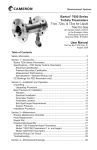
www.diverse-technologies.net
DIVERSE
MAGMETER MF500M
MAGNETITE METER
USER MANUAL
CAMBRIDGE
ENGLAND
CB22 5EW
www.diverse-technologies.net
Page 1
www.diverse-technologies.net
Contents
INTRODUCTION
FIRST TIME - QUICK START
OPERATION
OPERATION - OPTIONS
CALIBRATION AND PIPE OCCLUSION
MEASUREMENT TECHNIQUE
SPECIFICATION
LIABILITY
CALIBRATION AND REPAIR
DISPOSAL AND RECYCLING
Page 2
www.diverse-technologies.net
Introduction
Thank you for purchasing MF500M. Before using the unit,
please read these instructions carefully. If you are uncertain
about any aspect of its operation, please contact Diverse our
contact details are at the end of this manual.
The MF500M is designed to measure magnetite in nonmagnetic stainless steel pipes, particularly cooling pipes in
power stations.
The MF500M Magnetic Field Meter uses a force technique to
detect and quantify levels of magnetic material (particularly
magnetite) contained within stainless steel pipes. Because of
this, it is IMPORTANT that the pipe walls are not magnetic.
Page 3
www.diverse-technologies.net
First time, quick start
The unit requires 4 AA cells which should be installed in the
battery compartment on the rear of the housing.
Measurements are made by bringing the metallic front of the
probe into contact with the outside of the pipe. The probe is
sensitive to gravity and should be zeroed in the same
orientation as the measurement. Zero the probe before each
measurement
Quick start
1. Plug in the magnetite probe.
2. Load the AA batteries in to the battery compartment
ensuring that the polarity is correct
3. Press the power button (central yellow button), the unit
will switch on.
4. Hold probe away from pipe and depress button on probe
until a long beep is heard (zero value stored)
5. Take probe to pipe and press button, a double beep will
indicate measurement has been taken.
For a more detailed description of functionality see the
operation section.
Important note
The probe end should be placed no closer than 5mm to steel
or iron as this will stress the detector.
Page 4
www.diverse-technologies.net
Operation
Controls
There are 5 buttons on the meter and one on the probe with
functions as given in table 1.
Table 1. Button functions
Button
Colour
Function
enter
yellow
up
green
down
green
right
green
left
green
Probe
button
black (probe)
long press to turn unit off, short press to
turn on or select subsidiary function( e.g.
view records etc.)
scroll through records in <view records>
menu, toggle display type in <measure>
menu
scroll through records in <view records>
menu, toggle display type in <measure>
menu
select main menu (scroll through options)
and leave subsidiary menus
select main menu (scroll through options)
and leave subsidiary menus
short press take measurement and record,
long press store current value as
zero/offset
Button presses are accompanied by audible confirmation as
follows:
● single beep - menu select and at power on
● double beep - measurement recorded
● triple beep - unit powered off
● long beep - zero/offset value updated
Page 5
www.diverse-technologies.net
Operation - Options
Menus
<Measure>
This is the normal mode of operation
There are two display modes for this menu which can be
toggled using the up or down keys. Data is updated
approximately every second
The first mode displays the measured value, currently stored
offset and signal (difference) on the bottom line. The next
available record number is shown on the top line.
The second display mode estimates the amount of pipe
occlusion based on the current measured and offset values
(note there are a number of assumptions in these estimates see
section on calibration).
Note that data displayed on the first of these display formats is
what is recorded on a short probe button press.
<View records>
Press enter to view stored records (4 records shown, 1 record
per line). Enter toggles between two display formats.
Default format is record number, measure value, stored offset
and signal (difference between measured and zero/offset).
Alternative format gives record number and signal.
Use up and down buttons to scroll through stored records.
Continuous press of up or down scrolls records. Left and right
buttons leave view record menu.
Page 6
www.diverse-technologies.net
Operation - Options
<Clear records>
Press enter to clear records and set next record pointer to start
of memory.
<About>
Gives software version number
<Calibrate>
The instrument has two calibration factors used when
estimating pipe occlusion, gain and packing factor. The
following section gives details on how these factors are
calculated.
This menu option gives the user the opportunity to modify the
calibration factors. The up and down keys are used to select
the factors and the left and right keys increase and decrease
the selected factor. With gain or packing selected press enter
to store the values and exit to the main menu.
To revert to the factory calibration press enter button with
default selected.
Page 7
www.diverse-technologies.net
Calibration and pipe occlusion
A magnetite sample was used for calibration, This was a
cuvette 1cmx1cmx1.5cm packed with magnetite flakes. A force
measurement was recorded with the centre of a long side of
the cuvette 5mm from the centre of the probe measurement
surface (to simulate a pipe wall thickness). This value is taken
for the factory calibration gain and the software assumes that
this value corresponds to an occlusion of 75% in a tube of
40mm inner diameter and 5mm wall thickness.
By measuring the mass of the cuvette the density of the
magnetite flake sample was calculated and compared to the
density of solid magnetite. This gave a packing factor of 48%.
This factor is used in the display of occlusion for solid
magnetite.
Calibration settings can be altered using the <Calibrate>
menu.
User offset adjustment
The offset has been set to be nominally 50 counts with the
probe held horizontally. In the unlikely event that the offset
needs to be adjusted then this can be carried by adjusting the
potentiometer. Gently peel back the calibration label to
access the potentiometer using a small screwdriver, clockwise
will take the offset positive, anticlockwise will take the offset
negative. Replace the calibration label after adjustment. Note
that the meter’s range is nominally 0 to 1022 force units.
Page 8
www.diverse-technologies.net
Measurement technique
The meter provides a number that increases with the amount
of magnetite present. The following aspects should be noted:
1. The meter is sensitive to gravity so it is important that the
meter is zeroed, away from the pipe, in the same
orientation as the measurement to follow.
2. The meter is designed to work with a space between the
probe cap and magnetite. If the meter is too close to
magnetite (or indeed a ferritic sample) then a raw reading
of 1022 will be displayed.
3. Magnetite distribution will effect the measured value i.e. a
small amount of material close to the probe will give the
same signal as a larger amount further away.
Magnetite tends to accumulate on the corners of cooling pipes
where the pipes turn from vertical to horizontal. At these
points the pipe fills up from the bottom rather than
homogeneously as per our occlusion calculations.
Under these conditions we would recommend probing the
underside, the side and the top of the pipe around the
circumference. Due to the proximity of other pipes the
underside and top of the pipes may not be accessible so we
recommend probing positions A, B and C in the Figure 2.
As the pipe fills up the signal is expected to increase on A first
then B and finally C. Note the meter must be zeroed between
measuring points A, B and C but not between the same
orientations on the same or different pipes.
Page 9
www.diverse-technologies.net
Measurement technique
We recommend that a number of pipes are surveyed and the
measurements correlated with magnet tests and x-ray data.
From these results a measurement rational should be evident
that allows pipes with a particular occlusion to be readily
identified using the meter. An alternative formal rote is
described in the following section.
Figure 2. Pipe measurement
Page 10
www.diverse-technologies.net
Calculation of Magnetite from MF500M readings
Preamble
The magnetite meter measures the force on a powerful rare earth
magnet caused by the ferritic component of the magnetite. It is a
prerequisite of this technique that the containing pipe is stainless
steel which is not magnetic. In making the measurement the
instrument has a sensor that has some compensation for the
probe orientation in respect to gravity forces.
Clearly the magnetite could be in any amount at any point in the
pipe, but in reality there are only really 2 likely scenarios. Firstly
the pipe is fully filled and in normal use there is continuously
flowing water filling the tube. In this case the magnetite is likely
to be evenly deposited on the inside surface. (Note this is not
guaranteed and could be affected by turbulent flow or surface
finish attributes). The second scenario is that the magnetite has
accumulated on one side of the pipe. This can be due to a
horizontal pipe that is not fully filled, or accumulation of flakes of
magnetite building up under gravity. The measurement rote
attempts to identify which type of deposit is in place and then
estimate the deposit thickness from the measurement.
Before starting the probe should be placed in a position at least
1m from any magnetic material instrument should be zeroed.
This removes any constant offset in the measurement system to
be removed from all subsequent measurements.
Page 11
www.diverse-technologies.net
Calculation of Magnetite from MF500M readings
Measurement - phase 1
Placing the probe on any point on the surface of the pipe
slowly move the probe around the surface of the pipe keeping
the face of the probe at a tangent to the pipe surface. noting
the points where the reading is the highest and lowest Smax
and Smin.
Now we have to decide whether the magnetite is coating the
whole of the inside surface of the pipe or just a sector (as
would happen with a horizontal pipe where either flakes of
magnetite have accrued or the water has not fully filled the
pipe). From the analysis we have done, if the ratio Smax/Smin <
1.5 then the accrual might be deemed to be evenly coated.
Measurement - phase 2: even coating
A graph attached is the reading from the instrument for a
range of thickness and pipe sizes (internal diameter), so in
order to estimate the coating thickness locate the reading on
the y axis, trace horizontally to the curve for the pipe size
under test and then trace vertically down to the horizontal axis
and read off the estimated thickness.
Measurement - phase 2: sector coating
Starting at the point where the signal is a maximum (Smax)
with a chalk mark to indicate this position, slowly move the
probe round the pipe maintaining the probe at a tangent to the
Page 12
www.diverse-technologies.net
Calculation of Magnetite from MF500M readings
pipe surface until the signal has fallen to Smax/2. Mark the pipe again.
Repeat the prodecure in the other direction. In each case note the angle
from the Smax position take the average of these as θ (the half angle).
Defining the sector thickness t to be the thickest point of a sector
bounded by the inside of the pipe and a straight line across the arc, and,
R is the radius of the inside of the pipe.
The estimate of sector thickness, t is:
t = R * (1 - cos(θ))
Ratio of sector thickness to radius is:
q = 1 - cos(θ) —–––––( 1 )
(0 < θ < 90o)
Occlusion, f (fraction)
For θ in radians:
f = ( θ - (sin(2θ)/4) )/ π
For θ in degrees:
f = ( θ∗π/180 - sin(2θ ∗ π/180)/4 )/ π —–––––( 2 )
Expressions 1 and 2 are plotted below together with a simple linear
approximation that could be appropriate for quick assessments.
Page 13
www.diverse-technologies.net
MF500M Specification
Reading range
0 to 1022 force units
Occlusion
Technique
0 to 100%
Uses net magnetic force to identify magnetite
and magnetic material
Accuracy
Reading range: 0 - 1022 force units. These are
arbitrary units, and each instrument needs to
be calibrated to the specific pipe geometry and
magnetite samples
Can be zeroed at anytime - measurement
technique requires unit to be zeroed in the
measurement orientation
Measurement independent of probe orientation
provided it is zeroed first in that orientation
Zero
Probe orientation
Gravity
Zero removes gravity offset
Display
4 lines of 16 characters Shows value and user
interface messages
Functions
Raw force, occlusion for solid and broken
magnetite
500 samples per second
+/-5% assuming sample is degaussed
Internal data sample rate
Repeatability
Probe size
Detection
Storage
Probe cable length
Calibration:
Power:
20mm x25mm, 150mm long
Detects the magnetic force between the
sensing magnet and the magnetite. The signal
is offset by an estimate of the gravitational
force.
Maximum of 20 records can be stored
1.5m typical
Calibration is indicative only. Unit is supplied
with a calibration sample of magnetite so that
the instrument functionality can be verified
4 standard AA cells , typical lifetime 12 months.
Continuous use 30 hours
Instrument size:
Weight in case:
165 x 100 x 50mm
1.3kg
Environmental:
Humidity
Display update rate:
Warranty
10 - 40C operating, 0 - 80C storage
0-90% non condensing
0.3 seconds
12 months
Page 14
www.diverse-technologies.net
Liability
Diverse Technologies accepts no responsibility for the
consequential losses arising from the ability or inability to use
the equipment supplied. The limit of warranty is the repair or
replacement of any faulty components, directly attributable to
manufacturing defects, arising during the period of 12 months
following purchase. This does not include damage resulting
from incorrect operation of the instrument.
Designed and manufactured by:Diverse Technologies & Systems Ltd.
Zeromag House
46-48 Whittlesford Road
Shelford
Cambridge CB22 5EW
UK
Tel: +44 (0) 1223 84 44 44
Email: [email protected]
http://www.diverse-technologies.net
Page 15
www.diverse-technologies.net
Calibration and repair
The MF500M and probe is not supplied with a calibration
certificate. It’s operation is indicative only to be used to
determine the potential level of pipe occlusion.
IMPORTANT
This instrument uses magnetic force balancing and requires
specific equipment to set the unit up for optimum operation. If
the instrument requires repair this can only be undertaken at
Diverse Technologies. If the MF500M requires repair, the unit
should be returned to Diverse, there are no user serviceable
parts.
Page 16
www.diverse-technologies.net
Disposal and Recycling
This instrument should be deposed of in a responsible
manner to allow the components within it to be recycled.
The wheelie bin symbol shown here and on the product
means that the product is classed as Electrical and
Electronic Equipment and should not be disposed with
other household or commercial waste at the end of its working
life.
The Waste of Electrical and Electronic Equipment (WEEE)
directive (2002/96/EC) has been put in place in the EU to
recycle products using the best recovery and recycling
techniques to minimise the impact on the environment, treat
any hazardous substances and avoid landfill. Business users
should ensure that this product is not mixed with other
commercial waste for disposal.
Page 17