1
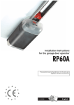
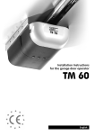
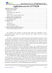
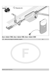
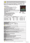
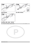
GARAGE DOOR OPERATORS
TM 50
TM 80
USER MANUAL
Note the operator‘s serial
number here:
Final Factory check by:
TM50/80 MO911/1V0 SKRW433 SKR433-1
ENGLISH
Content
General Information
Important Safety Instructions for the Users   ����������������������������3
General Information
Using the Operator   ����������������������������������������������������������������4
Devices
Usage
Manual Openings
In case of a Power Failure   �����������������������������������������������������5
Remote Control
Registering and deleting Remote Devices   �������������������������������6
Starting the Registry
Registering a Device
HomeLink™
Erasing Remote Devices
General Remarks   �������������������������������������������������������������������7
Useable Batteries
Changing the transmitters‘ battery
Changing the wall push-buttons‘ battery
Synchronisation of the Rolling Code
Technical Information
Adjusting the Lighting Duration   ���������������������������������������������8
General Troubleshooting   ��������������������������������������������������������8
Specific Troubleshooting   ��������������������������������������������������������9
Messages by blinking integrated lighting
If... then...
Technical Data   ���������������������������������������������������������������������10
Page 2
User Manual TM50 and TM80 - MO911/1V0
General Information
Important Safety Instructions for the Users
Please read these safety instructions carefully for your own
safety and the safety of others!
Your Seip TS door operator is up to the latest safety standards and
provides a high level of safety in use. Following the instructions on
this page will ensure a long term, trouble free operation.
- A garage door operator is not a toy - do not allow children
to play with it. Keep the hand-transmitter out of reach of
children!
- Only use the hand-transmitter when you can see the garage door! If the garage door cannot be seen, you could accidentally close the door whilst a car or person is passing by!
- When stowing the hand-transmitter please take care that
it is not activated accidentally! Be aware that the buttons
could be hit inadvertently and always stow the hand-transmitter
with its buttons facing upwards.
- Whilst entering the garage, store the hand-transmitter safely so that nobody can activate the operator - intentionally
or accidentally! Your garage door may be above your cars roof
and you may not be aware that the door has started moving.
- Always watch the moving door and keep persons away
until the garage door is either completely opened or closed!
- Do not leave any obstacles in the garage doors operating
range! Obstacles such as bicycles left momentarily could be
damaged when the operator is activated by another user!
- The emergency release must be used with care when the
garage door is opened - the door might fall down if the
springs are broken! Before using the emergency release on an
opened door your must ensure that neither persons nor obstacles
are within the doors moving range.
- Check the installation regularly for damages.
- Check the automatic reversion monthly using a 40 mm
high obstacle. Check the function every time adjustments or
changes are made to the garage door.
- Should problems occur with your remote-control then
please contact your dealer. Repairs should only be carried
out by an authorised dealer.
- The light bulb may be exchanged by taking off the operators‘ front cover. Please unplug the power cord before
taking off the front cover!
- The remaining parts of the operator may only be opened
by authorised personnel!
User Manual TM50 and TM80 - MO911/1V0
Page 3
General Information
Using the Operator
Devices
4-channel MIDI transmitter, 433 MHz
(2 units as standard equipment)
There are different devices available to activate your operator.
Standard Equipment:
- MIDI hand transmitter (4-channel)
- Remote Wall push button
Optional Extra:
- Key switch
- MINI hand transmitter (2-channel)
- Digi Pad
- Key Switch (cable bound)
- Receivers to control other devices with the MIDI transmitter
The devices may be used alongside each other.
Remote Wall push-button
(standard equipment)
Usage
The operator follows the principle OPEN-STOP-CLOSE. This
principle is valid for any device.
Starting from closing position of the door this means:
First impulse: the door opens
Second impulse: the door stops
Third impulse: the door closes
Fourth impulse: the door stops
Fifth impulse: the door opens
and so on.
2-channel MINI transmitter,
433 MHz (optional extra)
Usually it will not be necessary to stop the operator during
operation - unless you realise there is an unexpected obstacle
within the doors range.
Please also refer to the Safety Instructions on page 2.
The operator registers an obstacle when touching it - the garage
door hits the obstacle and reverses to set the obstacle free again.
Dependant on the make of the garage door slight damages might
occur on obstacles - a cars paintwork might become scratched.
Remote Digi Pad
433 MHz (optional extra)
With an additional security device like a photocell (optional extra)
the operator will stop as soon as an obstacle is recognised by the
photocell. Should the door be in the opening position the operator will only close the door once the obstacle has been removed
from the photocells range. With such a device contact between
the garage door and any obstacle is usually avoided.
Key switch
(optinal extra)
Please avoid to drop the hand transmitter - parts could
be damaged inside the transmitter. That might lead to
malfunctions!
Page 4
User Manual TM50 and TM80 - MO911/1V0
Manual Openings
In case of a Power Failure
You may disconnect your garage door from the operator using the emergency release. The emergency release is fitted to your operator in either
way shown on the diagrams on the right.
If your garage door is the only entrance to your garage then you can
disconnect the operator by using your garage doors lock and handle.
Unlock the door and turn the handle - the operator will be disconnected
automatically and you can open your door by hand.
If you have got a seperate entrance to your garage then you can enter
your garage and pull the cord hanging down in front of your garage door.
The operator will be disconnected and the door can be opened by hand.
ATTENTION: It might be dangerous disconnecting the operator from
an open garage door. If the doors‘ springs are damaged or the door
is not well balanced then it might drop down - there is a high risk
of injuries and damages!
If, however, you cannot avoid disconnecting the operator from an open
garage door then you must make sure that there is no one within the
range of the garage door before using the emergency release!
User Manual TM50 and TM80 - MO911/1V0
Page 5
Remote Control
Registering and deleting Remote Devices
In order to use a remote device it must first be registered with the operator. A total of 10 remote devices may be registered
with one operator, the registration must be made seperately for each device.
If the total of 10 devices is exceeded, the last registered device will be overwritten by the new one.
It is not possible to register more than one button of the same hand transmitter with the operator.
1
Starting the Registry
Keep the red LEARN-button pressed for 3 seconds. Release it once the red LED and the operators‘ lighting start blinking.
The operator now is in programming mode and awaits the signal from a remote device.
2
Registering a Device
Press the button that shall be used for controlling the operator for approx. 1 sec.
The red LED and the operators‘ lighting stop blinking - the device was programmed successfully. Pressing the devices‘ button again will run the operator.
Repeat steps 1 and 2 for any further device.
HomeLink™
Integrated car remotes usually use the HomeLink™ system by Johnson Controls. Systems from version 6 or higher are compatible with the operator.
First the hand transmitter must be copied into the HomeLink™ module (closer information on your specific system can be
found on the internet: www.eurohomelink.com).
The programmed HomeLink™ button will turn to a new Seip-compatible remote device. It therefore must be registered
with the operator just like any other remote device. Proceede as described in steps 1 + 2.
Erasing Remote Devices
The receivers‘ memory can be erased completely; it is not possible to delete single devices. To erase the receivers‘ memory
keep the red LEARN-button pressed for 10 seconds:
After 3 seconds the red LED and the operators‘ lighting will start to blink; after 10 seconds the red LED will come on permanently, release the LEARN-button then. The memory now is empty.
Page 6
User Manual TM50 and TM80 - MO911/1V0
Remote Control
General Remarks
Useable Batteries
Eine Batterie des Typs A23, 23A, 23L, EL12, VR 22 oder MN 21; Versorgungsspannung: 12V
Verbrauchte Batterien müssen nach den nationalen Bestimmungen entsorgt werden!
Changing the transmitters‘ battery
Open the transmitter
Take off lid
Change battery
Changing the wall push-buttons‘ battery
Change battery
A23S
Open the wall push-button
12V
Range
The TM operator is equipped with a high quality remote control set as a standard!
However, the remote control is the part of the operator which might be influenced by circumstances in the surroundings
of the garage. With our standard remote control you might reach a range of more than 100 meters.
The range is influenced by:
- old batteries: if you should experience a problem with the range, please change the batteries first. The lower the batteries run the lower the range will be.
- Building materials of the garage: In a garage made of concrete and steel you might reach a lower range than in an ordinary garage build of stone. The more steel was used for the walls the shorter the range of your remote-control.
Remote-control activity in the area: Radio and television transmitters close to your garage might reduce the range.
Older baby-phones and other household remote equipment: Some equipment like remote head-phones and baby-phone
might prodecure strong disturbant signals which could reduce the range of other remote devices.
It is extreemely unlikely that the range will drop to an unacceptable distance. If, however, problems should occure we will
like to be helpful.
Synchronisation of the Rolling Code
With each command given by a remote device a new code for the next command is created; this new code will be agreed
with the receiver. If a device is subsequently used for approx. 30 times out of reach of the receiver, then it will not be
accepted by anymore - the latest code is unknown to the receiver. The device must first be registered with the operator
again in order to use it (refer to page 16).
User Manual TM50 and TM80 - MO911/1V0
Page 7
Technical Information
Adjusting the Lighting Duration
The integrated lighting will be switched on with every incoming command. The adjusted time will run from the moment the
command was received.
Factory pre-set the light will stay on for 3 minutes. This time may be changed in steps of 10 seconds up to a total of
10 minutes.
To change the time proceede as follows:
Keep the red LEARN-button pressed for 6 seconds.
Release the button once the green LED comes on.
1
Press the red LEARN-button once again shortly.
The green LED now starts blinking: each blink stands for 10
seconds of lighting duration.
2
3
6 blinks = 1 minute
12 blinks = 2 minutes
18 blinks = 3 minutes
24 blinks = 4 minutes
30 blinks = 5 minutes
....
100 blinks = 10 minutes
Press the red LEARN-button shortly once the require time is reached. The green LED stops blinking and the new
duration for the integrated lighting has been stored.
General Troubleshooting
Occuring problems are not necessarily caused by the operator but by the garage door.
Your TM operator is equipped with an automatic force measurement. During the installation the operator memorises how much force it needs to open
and close your garage door.
Changes to the door weight caused by the weather (the door might go out of alignment slightly due to hot or cold weather conditions) will usually not
affect the operation of your door operator. The operator will also adjust itself to the normal and slow changes of your garage doors‘ performance caused
by ageing.
In contrast, rapid changes to the weight of the garage door will be recognised by the operator - the operator will then behave as if it had registered an
obstacle.
In CLOSING direction this means that the operator stops and reverses into opening direction to release a supposed obstacle.
In OPENING direction it means that the operator will stop and reverse a few centimetres into closing direction to release a supposed obstacle. During the
soft-stop period in CLOSING direction the operator will reverse for a few centimetres - the door will always remain open a few centimetres.
Rapid changes normally occur when:
- a spring of your garage door is broken; especially when the springs are covered by protectors you might not recognize the damage
- mechanical damages to the garage door happened (e.g. by hitting the door with a car)
- a new surface was attached to the garage door or the whole door was exchanged (e.g. an increase of the doors‘ weight)
In all of these cases the garage door needs to be maintained - please contact your dealer.
Page 8
User Manual TM50 and TM80 - MO911/1V0
Technical Information
Specific Troubleshooting
Messages by blinking integrated lighting
2 blinks
DIP-switch message: the DIP-switch setting was changed. Either
press LEARN-button to confirm the change or start the learning
cycles (page 12).
3 blinks
The end position could not be reached, the operator switched
off at time limit. Possible reason: motor damage or other mechanical problem.
5 blinks
Loss off data in the micro processor - try to start the learning
cycles (page 12). If this does not work the electronics must be
exchanged.
When the operators‘ light is blinking
The operator is also equipped with an error system - if an error should
occur then the operators‘ light will start blinking when you try to activate
it. The blinking light refers to errors caused by external devices - the following steps only need to be followed if any of the devices mentioned are
connected to your operator:
- check all security devices connected to your operator (photocell, security
beam or hatch door switch)
- check, that all obstacles are removed from the photo cells‘ range of
observation
- check if there is dirt on photo cell; clean if necessary
- check if the hatch door is closed
If the operators‘ light is still blinking after checking all devices then please
contact your dealer. The dealer will also find it helpful if you counted
the number of blinks given by the operators‘ light - it may give a hint
concerning the problem.
6 blinks
EEPROM error: The electronics must be exchanged
7 blinks
Relais damage - the electronics must be exchanged.
8 blinks
No impulses from the motors‘ hall-sensor. Possible reasons:
damaged hall-sensor, loose contact on the motor plug or damaged motor.
9 blinks
Amplifier for motor control is defective, the electronics must be
exchanged.
If... then...
The operator does neither react on the transmitter nor on the pushbutton
Power failure? Disconnect and connect the operator. Is the door stuck
because of snow and ice? Check the lines and the connections of the
push-button switch. Is there water in the push-button switch or in the key
operated switch? Disconnect alle external components and try running the
operator via the TEST/RUN button.
The light doesn’t work
Replace the bulb (230 V, max. 40 Watt)
The operator reacts on the transmitter but not on the push-button
switch
Check the line of the push-button switch. Does the push-button switch
work, when the remote receiver is disconnected? If so, the remote transmitter or receiver might be defective.
The motor is buzzing but the door doesn’t move
The door is jamming.
The operator reacts on the push-button but not on the transmitter
Check the battery of the transmitter. Try registering the transmitter with
the operator (page 16).
The operator neither reacts on the push-button nor on the
transmitter
Disconnect the receiver or remove the transmitter battery. Use your pushbutton switch only. If this solves the problem, your transmitter may be
defective. Disconnect the push-button switch and use your transmitter
only. If this solves the problem, the push-button switch or the line of the
push-button switch may be defective.
The operator isn’t running smooth
Unlock the carriage of the opener. Move the door manually and make sure
that the door is well balanced (must come to a stop at each position).
The spring tension is too high or there is even a spring fracture.
The operator works, but the door doesn’t move
The carriage is unlocked. If you want to lock it, open the door, but not
completely, and let the opener run. The carriage locks in automatically.
The operator doesn’t work due to a power failure
Unlock the carriage with the help of the emergency release and open
the door manually. (If you have a garage where you can only enter from
outside: Unlock the door with the key and turn the door-handle, then your
opener will be unlocked. If you have a garage where you can also enter
from inside: pull at the Bowden cable hanging from the carriage.)
The door doesn’t close completely and opens again
Is the door jamming while closing? Unlock the carriage manually (make
the door running well). Lubricate and oil the pivotal points of the door.
Run through the automatic learning cycle once again (page12).
User Manual TM50 and TM80 - MO911/1V0
Page 9
Technical Information
Technical Data
TM 50
TM 80
Nominal Pulling Force
50 kg
80 kg
Net Running Length
2,500 mm
Peak Pulling Force
60 kg
90 kg
Max. Running Length extended
4,000 mm
Overall Length
3,150 mm
Force-Setting for Operation
Motor
automatic
24V DC, low-noise
TM 50
TM 80
Height Motor Head
80 mm
Max. Running Speed
18 cm/sec.
14 cm/sec.
Length Motor Head
360 mm
Speed in Soft Mode
8 cm/sec.
8 cm/sec.
Width Motor Head
180 mm
Minimum Space above the door
35 mm
Time for 2,10m opening
11,5 sec.
16 sec.
Lighting
230V AC, max. 40W
Weight including packaging
Lighting Durance (adjustable)
10 sec. to 10 minutes
Noise Emissions
Duty Cycle
Stand By Power Consumption
Power Supply
Transformer
50%
2.0 watts
18 kg
≤ 60 dB(A)
Programmable Remotes
10 max.
Max. number of cars/garage
1
3
Subject to technical alterations!
190-250V AC
230V AC, 24V AC
Pre-Warning Light
adjustable
Automatic closing
adjustable
Maintenance: The operator is maintenance free! Do not
grease or oil the chain!
www.seip.com
Page 10
User Manual TM50 and TM80 - MO911/1V0