1
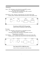
Data RS-232 Connection:
Terminal No.6: Signal being transmitted out over fiber
Terminal No.7: Signal being received in from fiber
Terminal No.8: Ground
*Terminal Block for Data Connection
Camera Site
Connect the Terminal No.7 (232T) in the terminal block connected from the transmitter
to RS-232 (232R) port of the controlled unit (pan/tilt, dome), and Terminal No.8 (GND)
is used for ground connection.
Control Site
Connect the Terminal No.6 (232R) in the data cable from the receiver to RS-232 Port
(232T) of the controlling unit (Keyboard Controller, Matrix, DVR), and the Terminal No.8
(GND) is used for ground connection.
Indicator LEDs
The stand-alone units have integral LEDs that are used to monitor the state of the unit.
There are one video LED, one power LED and four data LEDs on each unit. One,
labeled as “PWR”, lights when operating power is present. Another, labeled as “VID”,
lights when the video input/output signals are detected. The other one, labeled as
“DATA 1, DATA 2, DATA 3, DATA 4”, among them “DATA 2, DATA 3, DATA 4” are
normally on (unavailable), and “DATA 1” blink at the rate of the operating data. As
shown in the diagram in the following,
TRANSMITTER and RECEIVER:
Power: ON: (Orange) Indicates that correct power has been applied
6