1
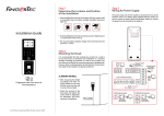
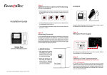
Step 1
Determine the Location and Positioning
of the Installation
• Avoid installing the terminals in locations with high moisture or
We Make Things Easy
•
condensation levels in the air
The recommended installation height of the terminal from the
ground is 1.2 meter.
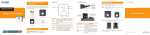
Step 3
Wiring for Power Supply
The power input ports for these models are located at the rear of
the terminals. There is no adapter plug supplied with the models,
instead you need to source for power cable (red and black cables)
to connect the power from the terminal to the AdapTec.
Kadex
Installation Guide
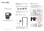
Step 2
Mounting of Terminals on A Wall
USB
Port
Back Plate
.
.
.
.
.
.
.
.
.
.
.
.
Door Lock connector.
Refer to Appendix I
GND
+12V
i-Kadex
4 feet / 1.2 meter
(recommended)
.
.
.
.
.
.
.
.
.
.
.
.
BEEP
.
.
.
.
.
.
.
.
.
.
.
.
GLED
RLED
.
.
.
.
.
.
.
.
.
.
.
.
.
.
.
.
.
.
.
.
.
.
.
.
Wiegand
IN
.
.
.
.
.
.
.
.
.
.
.
.
INWD1
GND
Power
OUT
+12V
3rd party
controller with
26 bits wiegand
output
DC12V 3A
Power
Supply
Kadex & i-Kadex
RJ45-1
Card Reader for Time Attendance &
Door Access Control System
RJ45-2
TCP/IP
• After determining the height of the terminal from the ground
level and have made the relevant marks on the wall, drill the
screws into the wall to hang the back plate.
Refer to Appendix II for dimensions and measurements of installation.
TCP/IP
1. RS485 Single Connection
485B
RX+
485A
RX-
RS232/RS485
Data Converter
485B
485A
485B
485A
RX+
RX-
RS232/RS485
Data
Converter
RJ45-3
RJ45-6
WD0
WD1
3rd party controller
with 26 bits wiegand
input
Wiegand
OUT
GND
RXD
2. RS485 Network Connection
w w w . f i n g e r t e c . c o m
INWD0
TXD
RS232
cable
RS232
GND
485+
485-
RS485
Step 5
Finalizing the installation
i-Kadex
1. Check that all cable connections are done correctly.
2. Attach the terminal to the corresponding back plates,
tighten the screws to secure the terminal on the wall
BEEP
BEEP
485B
NC2
ple
Pur y
Gre
Green
GLED
GLED
485A
COM2
3. Switch on the power to the terminal.
INWD0
RLED
GND
NO2
4. Start using the terminal.
White
Black
INWD1
INWD0
232T
NC1
GND
INWD1
232R
COM1
+12V
GND
GND
NO1
+12V
WD1
BUT
WD0
GND
Red
WIRES
Connects to the master
terminal and obtains
power supply
SEN
GND
+12V
Note: All Accessories are offered at http://accessory.fingertec.com
AdapTec
D OO R LOC K T
IM
ER
DC 12V 3A
Power Supply
RJ45-1
RJ45-2
RJ45-3
RJ45-4
Other Accessories
Back of a Master Terminal
Connection of i-Kadex to Kadex
Step 4
Setting Up Data Communications
(Skip this step if you are using USB flash disk to transfer data)
The data communication ports are positioned at the rear of the
terminals, please refer to the diagrams shown on Step 3 to determine the wiring. Plug the communication jacks (TCP/IP, RS232 or
RS485) to the corresponding ports.
TCP/IP – LAN Connection
For TCP/IP connection, plug the special RJ45 jack into the TCP/IP
(LAN) Port of the terminal. Connect the other end (normal RJ45
jack) to the local area network hub or a PC. Configure the device
ID, IP address, subnet mask and Gateway in the terminal (refer to
the hardware user manual for details).
RS232 – Serial Port Connection
Plug the communication jack that is provided in the package to
connect to the communication port of the terminal. Select wires
with label RX, TX and GND, and connect the other end of these
wires to a DB9 female connector. Configure the device ID and
baudrate of the terminal (refer to the hardware user manual for details).
Use the normal RS232 cable to plug into the RS232 port of the terminal.
RS485 – Serial Port Connection
Plug the communication jack that is provided in the package to connect to the communication port of the terminal. Select wires with label
RS485+, RS485- and GND, and connect the other end of these wires to
an RS232/485 data converter. Connect the other end of the data converter to a DB9 female connector. Configure the device ID and baudrate
of the terminal (refer to the hardware user manual for details).
AdapTec AC
The AdapTec AC is a 12VDC power supply inclusive of a 110~240VAC
switching linear power. The AdapTec supplies 12VDC power to
the FingerTec terminal and door lock system as well as charges a
12VDC 7.0Ah backup battery simultaneously. During an event of
a power failure, the back up battery automatically provides power
to the terminal and maintains the door lock system. The AdapTec
AC also prevents a secured door from being opened if it has been
tampered with.
Enclosures
FingerTec offers enclosures to protect the terminals from being
meddled with by unauthorized persons.
Door Lock Accessories
FingerTec offers various door locks accessories to complement FingerTec door access product range.
Appendix I
Power Supply & Door Lock System Wiring Diagrams
Diagram1 • Normally Close (NC)
EM
Lock (NC)
+
---
Emergency Break 2
Glass (Type NC) 3
Overwrite Switch A
(Type NC)
C
Door Lock Connectors
WIRING PORT USAGE
ALM+
ALMNC
COM
NO
ALM+
ALMNC
NO
BUT
Release Button
GND
SEN
BELGND
+12V
Diagram 2 • Normally Open (NO)
EM
Lock (NO)
+
---
Emergency Break 1
Glass (Type NO) 3
Overwrite Switch B
(Type NO)
D
Release Button
ALMCOM
SEN
BELGND
+12V
Diagram 3 • Other Accessories
Alarm device Type
NO or NC Dry contact
ALM+
ALMNC
COM
NO
BUT
Door Sensor
Doorbell
DC12V 3A
Power Supply
GND
SEN
BEL+
BELGND
+12V
Dry Contact (independent power supply for door
lock)
•NO type door lock (NOCOM)
•NC type door lock (NCCOM)
• COM1 - +12V
NO
GND
Dry Contact (independent power supply for door
lock)
•NO type door lock (NOCOM)
•NC type door lock (NCCOM)
Power Contact (using
power from terminal to
power on door lock)
NC
BEL+
DC12V 3A
Power Supply
COM
ALM+
BUT
Alarm System
(NO or NC Type – Check
in Advance Options)
Power Contact (using
power from terminal to
power on door lock)
•NO type door lock (NOGND)
•NC type door lock (NCGND)
BEL+
DC12V 3A
Power Supply
Appendix II
Terminal Dimensions and Measurements
BUT
GND
SEN
BEL-
Door Sensor
(SEN-GND)
Release button
(BUT-GND)
Door Bell
BEL+
The terminal will trigger the alarm
output (NO or NC) for the following situations:
• Door forced open (A door sensor must first be installed)
• Door open time out (A door sensor must first be installed)
• Terminal has been illegally dismantled
Front View of Kadex
Front View of i-Kadex