1
Contents
Chapter 1
Introduction
1.1 Introduction ............................................................................................................................. 9
1.2 Freescale Digital Signal Controller Advantages and Features ............................................. 10
Chapter 2
SR Motor Control Theory
2.1 Two Phase Switch Reluctance (SR) Motor........................................................................... 13
2.2 Digital Control of an SR Motor .............................................................................................. 15
2.3 Voltage and Current Control of SR Motors ........................................................................... 17
2.3.1 Voltage Control of an SR Motor ................................................................................... 17
2.3.2 Sensorless Position Estimation Using Phase Current Peak Detection ........................ 19
Chapter 3
System Concept
3.1 System Specification............................................................................................................. 21
3.2 Sensorless Drive Concept .................................................................................................... 22
3.3 Control Process .................................................................................................................... 22
3.4 System Blocks Description ................................................................................................... 23
3.4.1 Sensing of Phase Currents and DC-Bus Voltage......................................................... 23
3.4.2 Phase Current Peak Detection..................................................................................... 25
3.4.3 SR Motor Start-Up (Patent No. US6448736 B1) .......................................................... 27
3.4.4 Commutation angle control .......................................................................................... 28
3.4.5 PWM Modulation .......................................................................................................... 29
Chapter 4
Hardware
4.1 Hardware Configuration ........................................................................................................ 31
4.2 MC56F8013/23 Controller Board .......................................................................................... 32
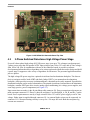
4.3 3-Phase Switched Reluctance High Voltage Power Stage................................................... 33
4.4 2-phase Switched Reluctance Motor .................................................................................... 34
Chapter 5
Software Design
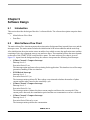
5.1 Introduction ........................................................................................................................... 35
5.2 Main Software Flow Chart..................................................................................................... 35
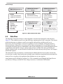
5.3 Data Flow.............................................................................................................................. 36
5.4 Processes Description .......................................................................................................... 37
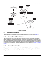
5.4.1 Process Current Peak Detection .................................................................................. 37
5.4.2 Process Manual Interface............................................................................................. 37
5.4.3 Process Application State Machine.............................................................................. 38
5.4.4 Process Ramp.............................................................................................................. 38
5.4.5 Process Commutation .................................................................................................. 38
5.4.6 Process PWM Update and DC Bus Voltage Correction............................................... 39