1
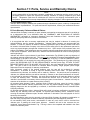
Section 9: Startup, Adjustments, and Shutdown A. Startup General Startup Information When possible, Johnston burners are factory test fired to ensure that components and systems are functional. All burners supplied on Johnston boilers are test fired as units, to as close to the minimum and maximum firing rates as practical. The fuel air ratio is adjusted as much as possible with the factory conditions. Because each field application is unique due to flue stack configurations, fuel composition variations, elevation, and other variables, the final burner setup and calibration must be conducted after system installation by a qualified burner service technician. Contact your Johnston Boiler Representative or the Johnston Boiler factory service department for scheduling and rates of factory authorized commissioning assistance. Burners supplied as stand alone items will not be fire tested. Where the word “boiler” is used, it will be synonymous with chamber or other device to which the burner is applied. Pre-Startup Checks: Boiler or Applicable Chamber Note: If your Johnston burner is to be installed on an apparatus not made by Johnston Boiler Company, follow the startup procedure given by the manufacturer of the product. The boiler/chamber is properly installed on a concrete pad, grouted and is level. The flue stack has been installed. A rain cap has been installed if directly connected to the flue gas outlet. The boiler/chamber’s piping, blowoff, blowdown, and feedwater systems have all been installed and connected according to the manufacturer’s instructions. The boiler/chamber’s doors and access openings are fully accessible. NOTE: Each Johnston burner is shipped with an order specification sheet, bills of material, piping diagram, wiring diagram, and other reference materials specific to this job. A thorough understanding of, and familiarity with, these documents is required prior to systems installation, commissioning, operation or trouble shooting. Pre-Startup Checks: Burner The electrical power supply has been run to the control panel. A disconnect has been installed at the control panel, just before the power supply enters the control panel. If the control panel was supplied by others, ensure that it is wired to match the wiring diagrams that came with your burner. All motor rotations have been checked (blower, oil pump, air compressor) against the direction of rotation labeled on the motor. Due to job-specific differences in motor setup, proper motor rotation is labeled by the factory using arrows. There is nothing about the installation that will no longer allow the burner and fuel train(s) to operate properly and be adjusted, as may be necessary. Fuel supply pressures match the specification sheet. Continuity and electrical check of any wiring that was required into the control panel. For oil firing, fuel oil has been circulated and strainers are empty and clean.