1
2.1.4 Module Slot Identification
The shelf is compliant with PICMG 3.0 R2.0, and accepts modules compliant with this standard.
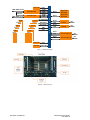
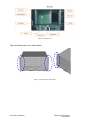
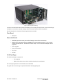
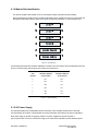
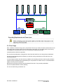
Figure 9 illustrates the locations of the module slot allocations when viewed from the front. The physical and
the logical slot allocations are the same for this shelf: the slots are numbered 1 to 6 from bottom to top.
Figure 9 – Slot Allocations
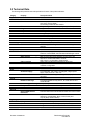
The following table shows the hardware addresses in relation to the slot numbers and slot addresses. Slots are
shown in the same order as they appear in the shelf: slot 2 above slot 1.
Slot
Hardware Address
Hardware Address
Number
(8 bit format)
(7 bit format)
6
8Ch
46h
5
8Ah
45h
4
88h
44h
3
86h
43h
2
84h
42h
1
82h
41h
Figure 10 - Shelf Addressing
2.1.5 AC Power Supply
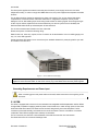
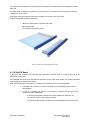
The field replaceable and hot swappable, 90VAC to 264VAC, power supplies provide power to the shelf.
The FlexChassis ATCA-SH61 is equipped with AC power inlets which are located in the rear for redundancy.
Each power supply is capable of supplying 1500W. Two power supplies are required to power a
fully-occupied shelf. The use of a third power supply is for cases where redundancy and/or additional power
Document CC09456-01
FlexChassis ATCA-SH61
User Manual