1
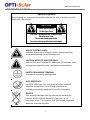
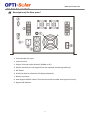
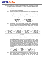
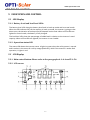
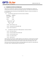
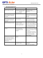
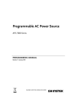
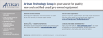
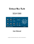
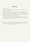
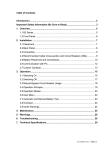
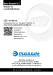
Inverter + UPS Hybrid Inverter series User’s Manual Sine Wave Output SP4000-AVR www.opti-solar.com www.opti-solar.com IMPORTANT SAFETY INSTRUCTIONS SAVE THESE INSTRUCTIONS. This manual contains important instructions that you should follow during installation and maintenance of the Inverter and the batteries. Please read all instructions before operating the equipment and save this manual for future reference. When replacing the batteries, use the same number and the same type of batteries. Do not dispose of batteries in fire; batteries may explode. Do not open or mutilate the battery or batteries, released electrolyte is harmful to skin and eyes. A battery can present a risk of electric shock and high short circuit current. The following precaution should be observed when working on batteries. Remove watches, rings or other metal objects. Use tools with insulated handles. To increase the balance of the inverter, the additional stabilizer is to be mounted at the bottom side. This unit should be installed by qualified personnel. The equipment can be operated by any individuals with no previous experience. The socket-outlet should be installed near the inverter and should be easily accessible. The total leakage current of the equipment connected to the inverter should not exceed 3.5mA. Attention: Danger of electric shock. The batteries connected to the inverter carry the charge that pose a danger of electric shock even when the inverter is disconnected from the AC mains. The battery supply should be therefore disconnected at plus and minus terminals by removing the battery fuses accessible from the rear panel of the inverter, before conducting maintenance or service work inside the inverter. The chemical substances of the lead acid batteries are hazardous. Batteries must be recycled 2 www.opti-solar.com CAUTION The inverter wiring and operation instructions in this manual must be followed strictly. The inverter must be connected to a nearby wall AC outlet, which must be easily accessible, so as to enable the inverter to be disconnected from the AC power source by pulling the power cord out of the AC socket, in case of emergency. Check that the indications on the rating plate correspond to your AC power system and to the actual electrical consumption of all the equipment to be connected to the inverter. Never install the inverter near liquids or in an excessively damp environment. Do not let foreign objects penetrate the inverter. Never block the ventilation grates of the inverter. Never expose the inverter to direct sunlight or a heat source. If the inverter is to be stored prior to installation, the storage environment must be dry. The storage temperature range is -15˚C to +55˚C. All handling operations require at least two people (unpacking, installation in rack systems). Once the inverter is installed and connected to the AC power source for the first time, it will start charging the batteries. Full charging to obtain the rated on-battery backup time requires at least 8 hours. Before and after installation, in case of any doubt, do not hesitate to contact our customer support team. 3 www.opti-solar.com Special Symbols The following are examples of symbols used on the unit to deliver you the important information. CAUTION Risk of Electric Shock Do Not Open Cover CAUTION To reduce the risk of electric shock Do not remove cover No user-serviceable parts inside For service refer to an authorized service agent RISK OF ELECTRIC SHOCK Indicates that a risk of electric shock is present and the associated warning should be observed CAUTION; REFER TO USER’S MANUAL Refer to this user’s manual for additional information, such as important operation and maintenance information. SAFETY GROUNDING TERMINAL Indicates the primary safety ground. RJ-45 RECEPTACLE For 230V units only, this receptacle provides network interface connections. Do not plug telephone or telecommunications equipment into this receptacle. RECYCLE This symbol indicates that you should not discard the inverter or the inverter batteries together with common trash. The inverter and the sealed, lead-acid batteries must be recycled. 4 www.opti-solar.com TABLE OF CONTENTS 1 OVERVIEW AND FEATURES ............................................................................ 6 2 INFORMATION PRESENTATION ..................................................................... 7 2.1 LED display models.................................................................................. 7 2.2 LCD display models ................................................................................. 7 2.3 Description of the Rear panel ................................................................. 8 3 INSTALLATION ............................................................................................... 9 4 OPERATION ................................................................................................. 10 5 INDICATION AND CONTROL ......................................................................... 13 5.1 LED Display ........................................................................................... 13 5.2 LCD Display ........................................................................................... 13 5.3 Audible alarms ...................................................................................... 15 5.4 Auto Self-test Function ......................................................................... 15 5.5 Remote Control ..................................................................................... 16 5.6 Reset the Inverter.................................................................................. 16 5.7 DIP Switch Settings ................................................................................ 16 6 COMMUNICATION INTERFACE ..................................................................... 17 7 TROUBLESHOOTING..................................................................................... 18 8 SPECIFICATIONS: SP4000-AVR ....................................................................... 19 5 www.opti-solar.com 1 OVERVIEW AND FEATURES The SP-AVR series inverters are advanced and user-friendly power supply units designed to provide pure sine-wave uninterruptible power to your connected equipment; besides the big charger capable of charging batteries with up to 35A current (depending on model), the inverter unlike the traditional ones, also provides a very short transference when blackouts happen; thus, you may apply it as a UPS, too. Further, it is also made with Wide Range AVR, offering an output as narrow as ±10% from the nominal power, while the input power range can vary as large as 140V ~ 310V in the rated 230V areas; or 70V ~ 155V in the 110V areas. With the wide AVR, you won't need to use the valuable battery energy during over- and under-voltages. The SP-AVR series provide the efficiency of over 97% under normal power conditions, and of 86% when working in the inverter mode. Two charge modes, quick and trickle charge, are applied in the charger, so as to maintain the batteries in the best condition. With outstanding performance and reliability, the unique benefits of the inverter include the following: Pure sine wave output. Microprocessor based design with true Line-Interactive structure, DC/AC Isolation. Remaining Estimated On-Battery Backup Time indication (EBT system on LCD version). Wide input range 140V~310V for 230V areas; and 70V~155V for 110V areas. Adjustable charging voltage & voltage-transfer points. Smart battery management with intelligent double stage charging control. Adjustable charging current by DIP switch for different types of batteries. Real time auto-detection of battery condition. Automatic restart after Inverter shutdown, when the AC power comes back. Smart AVR function (two buck and two boost modes). Generator compatible. Start on Batteries (cold-start) in the absence of AC mains power. “Green Power” design with auto on/off function and adjustable levels. Network manageable (optional SNMP support). Optional RS-232/USB interface for communication, compatible with all major operating systems, including Microsoft Windows, Linux, SCO UNIX and DOS. Protection for overload, short circuit and overheat; thermal controlled cooling fan. Supports solar panel input for charger (Optional) 6 www.opti-solar.com 2 INFORMATION PRESENTATION 2.1 LED display models There are variations for information representation via LED indicators for different models, still they share the same control method. Please refer to the following example: LEDs of battery voltage level and load level. LED of operation status. Control Button 2.2 LCD display models The following is one example of LCD display; the location of control buttons could be different for some models; however, the functions of buttons are the same. Main control button. LCD screen. Selection button for mode & value. 7 www.opti-solar.com 2.3 Description of the Rear panel 1. Circuit Breaker for Input. 2. Input Terminal. 3. Output Terminal and/or Outlet(s) (NEMA or IEC). 4. RS-232 Interface port (for applications with optional monitoring software) 5. DIP Switch. 6. RJ-45 Interface for a Remote LCD display (Optional). 7. Battery connector. 8. Auto-bypass ON/OFF Switch (Turn the switch ON to enable Auto-bypass function). 9. Bypass LED Indicator. 8 www.opti-solar.com 3 INSTALLATION 3.1 Inspect the packing carton for damage that may have occurred while in transit. Immediately notify the carrier and your reseller if any damage is found. Retain the package for future use. 3.2 Plug the power cord into a 3-wire grounded AC power wall receptacle. If an extension cord must be used between the Inverter and the nearest utility power source, use a 3-wire cable with rating not less than specified for the load level you are going to connect, as stated in paragraph 8 of the specifications. 3.3 Connect the DC input power cord to the battery bank. Mind the battery bank’s voltage and the polarity. The inverter must be as close as possible to the battery bank to avoid the voltage drop on the power cord. 3.4 Connect your equipment to the Inverter. To ensure your home appliances are powered and protected during utility failures, it is important to make sure that the maximum power needed by the equipment is not exceeding the rated capacity of the Inverter. Red LED will light up (LED version), or the “Over load” symbol will show up (LCD version), and alarm will beep if the load exceeds the rated value of the Inverter. If the overload is severe, the Inverter will shut down immediately to protect itself. 9 www.opti-solar.com 4 OPERATION 4.1. Once connected to the normal city power, the inverter will automatically start charging the batteries. When the inverter is OFF, the inverter would still perform the battery charging, and the status LED (in LED version) would blink green every 2 seconds; or in LCD version, the battery symbol and battery level would blink every second. If AC auto turn-on function is enabled, the inverter turns ON automatically when city power is normal. If auto turn-on is disabled, please long-press the ON/OFF button on the front panel for 1 second to turn the Inverter ON; the Inverter will give power to the outlets. 4.2. Long-pressing the ON/OFF button for 4 seconds will turn OFF the power on the outlets. But, the inverter will keep charging the batteries if the city power is normal. To stop the charging, please pull out the Inverter input power cord to shut down the inverter completely. 4.3. DC Start: During a blackout, long-press the ON/OFF button for 1 second to enter the “OFF” mode (LCD showing “OFF” or LED blinking in amber); then long-press the ON/OFF button again for 1 second, and the inverter will turn ON and enter into onbattery mode. To turn OFF the power from inverter please long-press the ON/OFF button for 4 seconds; then the status LED (in LED version) will start blinking in amber every 2 seconds; or LCD display will show “OFF” (in LCD version); then after 10 seconds the Inverter will turn OFF the power. 4.4. Auto-Bypass: When the auto-bypass function is enabled, the Inverter will transfer to by-pass mode any time when the inverter is turned OFF. It prevents the important connected equipment from a power loss if overload or any abnormal situation triggers the shut-down function of the Inverter. 4.5. When in on-battery mode if the battery voltage is too low or too high, the inverter emits an alarm, if the under voltage or over voltage is severe, the inverter turns OFF. 4.6. When a blackout happens, the buzzer emits two beeps every 8 seconds during the first minute of the blackout. You can disable the alarm by a short-pressing the main control button. Short-pressing it again re-enables the alarm. The setting can be seen on the LCD display. Note: The main control button provides test function at normal mode, but gets an alarm-reset function when in on-battery mode. 4.7. The Inverter provides two charging modes for the battery: quick charging and trickle charging. The quick charging provides higher charging current when battery is empty and reduces the charging current as the battery voltage increases. The trickle charging begins automatically after the battery is 90% fully charged. 4.8. The Green mode is set up using the UPS wizard software or through the LCD display. When “Green Power” function is enabled, the inverter turns OFF the power within 60 seconds after blackout occurs if the power consumption of the connected equipment is lower than the pre-set level (adjustable from 1% to 14% of full load). The default value of green mode setting is 0% (disabled). Please use the UPS wizard software to adjust this level. 10 www.opti-solar.com 4.9. There are two ways to change the settings of the Inverter. The first way is to use the UPS Wizard software. The second way is to make it through the LCD display, using the following steps: 4.9.1. Press the two selection buttons and at the same time for 3 seconds until the LCD display begins to blink. 4.9.2. To change the inverter O/P frequency at DC start, when the frequency value is blinking, push any selection button, or for 1 second to change the frequency setting. The setting will keep changing every 2 seconds if you keep pushing the button. Push two selection buttons at the same time for the next setting, or leave the LCD blinking without pushing any button for 30 seconds to finish setting the Inverter and to return to the normal mode. 4.9.3. To change the inverter rated voltage, when the voltage value is blinking, push any selection button for 1 second to change the rated voltage. Keep pushing the button until the required voltage appears on the LCD screen. Then, push two selection buttons at the same time to change to the next setting or leave the LCD blinking for 30 seconds to finish setting the Inverter and to return to the normal mode. 4.9.4. To change the Auto-Turn-ON setting at the recovery of utility power choose the required setting the similar way. If you do not need the Auto-Turn-ON function, please select “oFF”. Select “On” if you need you Inverter to turn ON immediately after the recovery of the utility power. The “On.S” means auto turning ON in the safe mode. When the battery has been depleted after a long blackout, after the utility has been restored, the Inverter having the Auto-Turn-ON function enabled would turn ON but would have a very short on-battery backup time if a blackout is to happen again following a short time recovery. Selecting “On.S” will ensure that the Inverter turns ON automatically only after the battery has been charged up to at least 30% of its capacity. 4.9.5. To change the green mode level browse the LCD settings until you see the “Gn.X” indication, where X is any digit 0~9. If the “Gn.0” is blinking, the green mode if disabled. The inverter will not turn OFF the power 11 www.opti-solar.com automatically if there is no load connected to the Inverter. If the “Gn.1” is blinking, the green mode level is set to 1% of full load. The inverter will turn OFF the power automatically after a blackout occurs if the load level is less than 1% of the rated full load. Push the selection button for 2 seconds at least to increase the green mode level or push the to decrease the level. Push the two selection buttons at the same time to end the setting. 12 www.opti-solar.com 5 INDICATION AND CONTROL 5.1 LED Display 5.1.1 Battery level and load level LEDs The battery level LEDs show the battery level both in back-up mode and in normal mode. When the LED indicates 20% of the capacity in back-up mode, the Inverter is going to shut down soon; the duration of backup time left depends on the load. When all five LEDs are lighted in normal mode, the battery is fully charged. The load level LEDs show the percentage of added load in relation to the Inverter’s rated capacity. When all five LEDs are lighted, the Inverter is over loaded. 5.1.2 Operation status LED The status LED shows the Inverter status. It lights in green when the utility power is normal and in amber in the event of a utility outage (blackout); while if the Inverter is under fault operation, it lights in red. 5.2 LCD Display 5.2.1 Main control button: Please refer to the paragraphs 4.1~4.6 and 5.3~5.4. 5.2.2 LCD screen 13 www.opti-solar.com No. Symbol Indication Description 1 Overload The total load of the equipment connected to the Inverter exceeds the rating of Inverter. 2 Load level The higher the load, the more bars illuminate. Normal mode When the “Green Mode” is enabled, this symbol is displayed when the load is over a preset level (adjustable, default is 0% = disabled), and disappears when the load is under a preset level. Please refer to the paragraph 4.9.5. When the “Green Mode” is disabled, the symbol is always displayed. 1) The sine wave symbol will display steadily without battery symbol when the Inverter is in the normal mode. Battery mode 2) The sine wave symbol and battery symbol will blink when the Inverter is in on-battery (inverter) mode. Test mode 3) The sine wave symbol will display steadily with blinking battery symbol when the Inverter is in the test mode. 5 Buck mode The AVR (Auto Voltage Regulator) is reducing the output voltage of the Inverter (when the input voltage is too high), and the sine wave symbol, as mentioned in item 4, is also displayed steadily to indicate that the Inverter is in the normal mode. 6 Boost mode The AVR is increasing the output voltage of the Inverter (when the input voltage is too low), and the sine wave symbol, as mentioned in item 4, is displayed to indicate that the Inverter is in the normal mode. Inverter is loaded 3 4 Timer is enabled 7 8 HIGH Fan is at “High speed” 9 10 11 12 LOW 13 14 Thermal alarm This symbol will show up in the following situations: 1) A Turn-ON / Turn-OFF schedule has been set using the monitoring software. Refer to paragraph 5.5 and the “Readme” file or “Help” function of the monitoring software. 2) The Green Mode is enabled and the load is under a preset level. The Inverter will turn OFF automatically in 60 seconds. Refer to the paragraph 4.9.5 of this User’s Manual. The temperature inside the transformer is over 90˚C. If the user does not reduce the load, the temperature will continue to rise and the inverter will shut down automatically after reaching 95˚C. The symbol will display whenever the cooling fan is running at high speed, and will disappear when it is off (or running at low speed). The audible alarm has been silenced. To reset the alarm while in onSilence mode battery mode, push the control button (not available when the battery is low or if Inverter abnormal condition is detected). The Inverter has failed and must be repaired. Contact a qualified service Inverter fault person. Battery 1) In normal operation, this symbol indicates a charged battery. normal 2) When the battery charge level is low, the word “LOW” will be added Battery low to the symbol. Battery reThe battery has failed and must be replaced. The battery is checked placement each time the Test Function is executed. required 1) The higher the battery voltage, the more bars will illuminate. Battery 2) When the Inverter is charging the battery, the battery symbol and the charge level level indicator blink together. 14 www.opti-solar.com No. 15 Mode Value AC out AC in AC out BATT. TEMP. V V Hz V ˚C Description AC output voltage AC input voltage AC output frequency DC battery voltage Inverter internal temperature The Inverter will turn OFF when the displayed value reaches zero. For TIMER Mins to OFF example, if the timer shows 0.5 Min to OFF, the Inverter will shut down in 30 seconds. The Inverter will turn ON when the displayed value reaches zero. For TIMER Hrs to ON example, if the timer shows 48 Hr to ON, the Inverter will turn ON in 2 days. The estimated remaining run time in on-battery mode. The accuracy of BATT. Mins to OFF the value is influenced by the load type, ambient temperature and battery condition (old or new). Selection Button for mode and value All the operation data is displayed on the LCD screen. By selecting the required mode (upward or downward), the related value is displayed. 5.3 Audible alarms During a utility failure or in case of an Inverter failure, the Inverter produces a sound alarm. When in on-battery mode, the Utility Failure alarm can be silenced by pushing the Silence button. However, the Battery Low warning cannot be muted. Basic Indication Table: STATUS Utility Good Utility Outage Idle mode Timer ON, (refer to Item 5.5) Normal (Utility good) Normal / On-battery On-Batt. (No load) On-Batt. (Loaded) mode Battery Low Overload Abnormal Condition Inverter fault Thermal alarm ALARM No Beep No Beep REMARK (LED) Green (flash) Amber (flash) No Beep Red (flash) No Beep Green One beep every 4 seconds (alarm can be silenced) 2 beeps every 8 seconds (during 1st minute of blackout) 4 beeps per second (alarm cannot be silenced) Continuous alarm (alarm cannot be silenced) Every other 2 seconds, 3 beeps in 2 seconds (alarm cannot be silenced) Every other 2 seconds, 3 beeps in 2 seconds (alarm cannot be silenced) Amber (flash) Amber (flash) Red Red (flash) Red (flash) 5.4 Auto Self-test Function In normal mode of Inverter, connect some load and push the Self-Test button on the front panel to perform the self-test. The Inverter will simulate a power outage and transfer to battery mode. If Battery Low warning sounds during the test, the battery is weak and requires an extended charging. 15 www.opti-solar.com 5.5 Remote Control The Inverter can be set for daily shutdown/wake up. This command must be set through the RS-232 interface. When this function is set, the timer inside the Inverter will start, and the load will be turned OFF according to the shutdown / wake-up schedule. During the period between a Turn-OFF and a next Turn-ON, the status LED would blink red every 2 seconds. If your Inverter has an LCD display, the time duration to the next Turn-ON will be shown on the LCD screen measured in hours (Refer to item 15 of the LCD description). 5.6 Reset the Inverter If any abnormal condition occurs, and the actions described in the paragraphs 4.1~4.7 cannot be executed, please unplug the AC input power cord and push the ON/OFF button for at least 15 seconds. This will reset the Inverter. 5.7 DIP Switch Settings Two options: one is for setting the charger parameters, and the other is for setting the system’s nominal voltage and frequency, which can also be adjusted using the UPS Wizard or LCD display. DIP 1 DIP 2 Charging current Up Up 35% Down Up 55% Up Down 75% NOTE of Charging current control: The setting of DIP 1 & 2 is valid only when the DIP3 = Down, which also means that the charger (built in the main PCB) is ON so that the charging current is adjustable, 25%~100%. While if the DIP3 = Up, it means that the built-in charger is OFF. Down Down 100% DIP 3 = Down, built-in charger is turned ON; DIP 3 = Up, built-in charger is turned OFF. DIP 4 is for the Green Mode setting: UP = Enabled; Down = Disabled The setting becomes active only after the inverter is restarted. 16 www.opti-solar.com 6 COMMUNICATION INTERFACE The Inverter provides two computer interfaces: RS -232 and USB (optional). The RS-232 interface also has the dry contact function (DB-9, optional). The models with USB interface are utilizing the same control port for both USB & RS -232 ports, so only one interface can be used at a time. 6.1. The definition and setup for RS-232 is shown as follows: Baud Rate : 2400 bps Data Length : 8 bits Stop Bit : 1 bit Parity : None 5 4 3 2 1 9 8 7 6 Pin #6 : RS-232 data Tx out. Pin #7 : Common of Pin #6 and Pin #9 Pin #9 : RS-232 data Rx In 6.2. The definition and setup for DB9 (optional) is shown as follows: Pin #2 : AC Power Failure Pin #4 : Common GND of Pin #2 & Pin #5 Pin #5 : Inverter Battery Low Pin #6 : Turn OFF Inverter Pin #7 : GND of Pin6 The interface with computer is shown above for your reference. Use Pin #4 as the common of Pin #2 and Pin #5, Pin #2 and Pin #4 will become close loop from open when the utility fails, Pin #5 and Pin #4 will become close loop from open when the battery level is low. The Inverter will shut down itself after receiving the high level from RS-232, sustainable for 3 seconds, which is applied between Pin #6 and Pin #7. 17 www.opti-solar.com 7 TROUBLESHOOTING Problem Inverter shows no reaction when AC input is connected Possible Cause 1. Line cord plug is loose 2. Fuse on rear panel is blown (located Inside the drawer of the inlet) 3. Dead wall socket Power output is normal, Inverter Inverter is overloaded emits continuous beep, status LED shows RED, or LCD shows “overload”. Action to Take 1. Check the line cord plug 2. Replace the fuse 3. Check the wall socket with a desk lamp. No power on outlets, Inverter emits continuous beep, status LED show RED or LCD shows “overload”. Inverter has shut down due to severe overload. Unplug excessive load from Inverter, press the Silence button to reset the buzzer, and turn ON the Inverter again. Inverter does not provide expected on-battery run time. 1. Excessive load is connected to Inverter’s outlets. 2. Battery is weak and cannot provide enough capacity. Do not operate the Inverter, leave the Inverter plugged in for 10 hours. Then test it again. If the Inverter still cannot provide the expected runtime, the battery should be replaced. Button on the front panel does not work. 1. The CPU inside the Inverter is not running correctly. 2. The button has been damaged. Pushing the Self Test button to test the Inverter running in AC mode, makes the Inverter to emit urgent beeps and the LCD display shows “Battery replacement”. Battery is weak and should be replaced. 1. Unplug the AC input power cord and push the ON/OFF button for 15 seconds to reset the Inverter. 2. Unplug all the load and the AC input power cord from the Inverter to let it turn OFF automatically, and call for service support. Replace the batteries. Inverter cannot be turned ON. 1. Battery polarity is wrong. 2. Inverter is faulty. 18 Turn OFF the Inverter and unplug the excessive load from the Inverter. Turn the Inverter back ON. 1. Check the battery connection. 2. Call for service support. www.opti-solar.com 8 SPECIFICATIONS: SP4000-AVR Input Nominal Voltage Input Frequency Efficiency (Normal mode) Noise Filtering Overcurrent Protection Voltage Range AVR Range (2 Buck, 2 Boost) Surge Protection Output Power Level Output Voltage Voltage Waveform Crest Factor Output Frequency (sync to mains) Voltage Regulation (nominal) Voltage Regulation (on-battery) Transfer Time Overcurrent Protection Battery Battery Type Voltage Charging Method Maximum Charging Current Average Charging Voltage for each battery Protection Monitoring 230V 47Hz – 65Hz, 50/60Hz autosensing 97% Full time EMI/RFI filtering Re-settable overcurrent circuit breaker protector 140V – 310V Enhanced Buck: +28% of selected nominal voltage Buck mode: +10% of selected nominal voltage Boost mode: -10% of selected nominal voltage Enhanced Boost: -25% of selected nominal voltage 440 Joules 3000W 230V Pure sine wave 3:1 Auto Select for 50/60Hz 47Hz – 55Hz for 50Hz nominal 56Hz – 65Hz for 60Hz nominal ±10% nominal voltage ±3% of selected output voltage (adjustable with the remote set-up software) Blackout: 3ms typical Over- and under-voltages: 1ms typical Battery mode to Normal mode: 1ms typical Overload alarm level 100% – 120% Overload shutdown level 120% – 190% (Adjustable by using the remote set-up software) Lead-Acid 50Ah – 500Ah (Recommended) 48Vdc Smart pulse charging with two charging modes: Quick charging when battery is not fully charged; Trickle charging after battery is 90% charged. 30A Quick charging mode: 14V maximum Trickle charging mode: 13.5V (adjustable with the remote set-up software) Overcurrent protection & charging overvoltage protection (SCR control) Thermal protection (CPU control) When the temperature inside the unit is over 45°C, the charger stops charging for 2 minutes followed by 2 minutes charging. The cycle will repeat until the temperature is lower than 44°C. Smart monitoring & warning for failed battery or open-circuit battery. Battery auto-detection each time during power ON or every 6 days. 19 www.opti-solar.com Solar Charger (optional) Rating Voltage DC Input Range Charging Method Charging Voltage Power Rating Protection Communication and Management Standard Interface Port Optional Interface Port Control Panel Audible Alarms Green Mode Function Cooling Fan Control Environmental Operating Temperature Transit/Storage Temperature Relative Humidity Operating Altitude Physical Dimensions (unit/packing) D×H×W Weight (Net/Gross) 48V 48 – 84Vdc Constant voltage with current limited by PWM control 54Vdc 1000W (54Vdc @ 18.5A) DC input polarity protection DC input short circuit protection (when battery is connected) DC output overcurrent protection UPSilon2000 compatible; optional for RS232 and/or USB. RJ45 (Surge protection), DB9, SNMP (external type) LCD Alarm on battery: Low battery & Battery over voltage Alarm on abnormal operation: Overload, Short-circuit, & Overheat 1% to 14% of full load (adjustable by using the remote set-up software) The default setting is OFF. Auto on/off, controlled by temperature & operation mode Up to 1500 meters: 0°C to 40°C (32°F to 104°F) -15°C to 55°C (5°F to 131°F) 5 – 95% (non condensing) 0 – 3000 meters 22×44×27cm / 36×61×41cm 38kg / 41kg 20