1
1
Summary .......................................................................................................................................... 4
1.1
FC5080 System features: ........................................................................................................ 4
1.2
Software functions: .................................................................................................................. 4
2
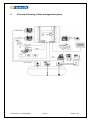
Schematic Drawing of tank management system ............................................................................ 5
3
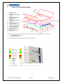
FuelCom Assembly Drawing........................................................................................................... 6
®
3.1
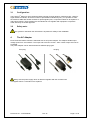
Configuration: .......................................................................................................................... 7
3.2
Safety note:.............................................................................................................................. 7
4
The AC Adapter ................................................................................................................................ 7
5
Installation of the Control Unit .......................................................................................................... 8
5.1
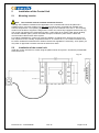
Mounting location..................................................................................................................... 8
5.2
Installation of the control unit ................................................................................................... 8
5.3
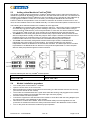
Adding a New Module to FuelCom 5080 ................................................................................ 9
5.4
Module installation procedure.................................................................................................. 9
®
6
Wiring the Control unit .................................................................................................................... 10
7
FuelCom Grounding Bar (Ex zone). ............................................................................................. 11
®
®
7.1
Assembly of Grounding bar inside FuelCom ....................................................................... 11
7.2
Installation of the cables into the cable glands. ..................................................................... 12
7.3
Connection to IS- ground. ...................................................................................................... 12
8
Wiring of the control unit to external devices ................................................................................. 13
9
Planning Sensor and Probe Installation ......................................................................................... 14
9.1
New sites ............................................................................................................................... 14
9.2
Existing sites .......................................................................................................................... 14
9.3
Intrinsically safe wiring issue ................................................................................................. 14
9.4
Grounding issue..................................................................................................................... 14
9.5
Wiring conduit safety issue .................................................................................................... 14
9.6
Cable ..................................................................................................................................... 14
9.7
4tech installation cable .......................................................................................................... 15
9.8
Sealing the conduits .............................................................................................................. 15
10
Probe and sensor introduction ................................................................................................... 16
®
10.1
FuelBar 410/420 and P44 probe ........................................................................................... 16
10.2
MiniBar ................................................................................................................................... 16
10.3
FuelBar probes, range of variation: ...................................................................................... 16
10.4
Differences in FuelBar 410/420 probes: ............................................................................... 17
10.5
Separate overfill prevention sensor: ...................................................................................... 17
®
®
®
11
The AirTrap Functionality. ........................................................................................................ 18
12
Oil separator and overflow sensor. ............................................................................................ 19
12.1
Description of the KVF oil separator ...................................................................................... 19
12.2
The NVF (PTC thermistor) Sensor installed as an Overflow Alarm. ..................................... 19
13
®
Modules of FuelCom 5080 ........................................................................................................ 20
Document no.: 15-CFC09026
Rev. B
Page 2 of 34