1
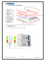
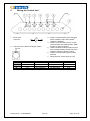
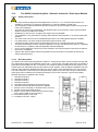
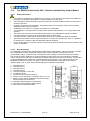
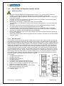
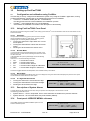
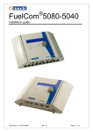
13.2 13.2.1 The AD424 Intrinsically Safe - Galvanic Isolated 4...20mA Input Module Safety instructions The input module is designed for Ex applications in zones 0, 1 or 2, but the module itself is not suitable for mounting in an explosive atmosphere, it must be installed in a safe area. The temperature class and explosion group as well as the special conditions marked on the product have to be respected! According to the EC-type examination, the following limits of Ex-Protection must not be exceeded: AD424: Uo=24,74 Io=90mA Po=0.65W Modification of the device or changes of its design are not permitted! The installation is only permitted in housings with minimum IP20 protection or in closely supervised systems. The device has to be used for its intended purpose and in an undamaged and proper condition. For replacement, only 4tech original replacement parts must be used. Components which need repair must be shipped to 4tech AS. Unauthorized repair is forbidden. Service that will influence on the explosion protection is only to be carried out by 4tech or a qualified Ex electrician in compliance with the applicable national standards. Prior to its first start-up the device has to be checked in accordance with the instructions as listed in the section “installation”. Observe the national safety rules and regulations for the prevention of accidents as well as the safety instructions given. 13.2.2 Brief Description The AD424 is an intrinsically safe galvanic isolated 4…20mA input module, which provides the user with four independent channels of transmitter power and 4…20mA inputs. The data output from the module is presented on the RS485 local bus. If more than one module of AD424 is added to the bus system, each module has to be addressed using the DIP-switch on each module. (See the AD424 installation and user manual). Each channel is labelled with letter from A to D. When a loop powered device is connected to one of the channels, a red led is set to indicate that the polarity of the connection is right. A flash on the green (RX) LED is indicating a successful transmission from a host computer. A green LED (PWR) indicates that power is applied to the module. 1. 2. 3. 4. 5. 6. 7. 8. 9. LED Red channel B LED Red channel A LED Red channel C LED Red channel D LED Green RX transmission received from host LED Green power indicates that power is applied Snap in foot for mounting on 35mm din rails. (EN 50022) Printed circuit board inside housing Button on each side to release the top of the housing. Pull to get the PCB out of the housing 10. IS Screw terminal on each side 11. Local Bus connector, 10pole. Document no.: 15-CFC09026 Rev. B Page 21 of 34