1
i-ais-AN1
AIS AtoN (Aids-to-Navigation) Station
Installation and User Manual
Rev. 2.1
2011
i-ais-AN1
Installation & User Manual
IMPORTANT NOTICES
The operator of this equipment must read and follow the descriptions in this manual.
Wrong operation or maintenance can cancel the warranty or cause injury.
Do not copy any part of this manual without written permission from iDeal Teknoloji.
If this manual is lost or worn, contact your dealer about replacement.
The contents of this manual and equipment specifications can change without notice.
The example illustrations shown in this manual can be different from the screens you
see on your display. The screens you see depend on your system configuration and
equipment settings.
Save this manual for future reference.
Any modification of the equipment (including software) by persons not authorized by
iDeal Teknoloji will cancel the warranty.
All brand and product names are trademarks, registered trademarks or service marks
of their respective holders.
Revision 2.1
2
i-ais-AN1
Installation & User Manual
SAFETY INSTRUCTIONS
The operator and installer must read the applicable safety instructions before attempting to
install or operate the equipment.
Revision 2.1
3
i-ais-AN1
Installation & User Manual
Revision History
Revision
Date
Notes
Prepared by
v1.0
12.10.2009
Draft
Taner AKDENİZ
v1.1
13.10.2009
General update
Sedef ÜSTÜNDAĞ
V1.2
19.10.2009
Update about images
Sedef ÜSTÜNDAĞ
V1.3
26.11.2009
General update
Taner AKDENİZ
V1.4
31.12.2009
General update
Taner AKDENİZ
V1.5
30.03.2010
Update for Approvals
Taner AKDENİZ
V1.6
08.10.2010
V1.7
28.10.2010
Corrections
Taner AKDENİZ
V1.8
19.04.2011
Corrections
Taner AKDENİZ
V1.9
18.07.2011
V2.0
27.07.2011
V2.1
11.10.2011
Revision 2.1
Update for Power
Consumption
Update for BSH
Requirements
Update for Remark for
VHF Antenna VSWR
BSH Cert.
Taner AKDENİZ
Taner AKDENİZ
Taner AKDENİZ
Taner Akdeniz
4
i-ais-AN1
Installation & User Manual
TABLE OF CONTENTS
1.
AIS System General Information ............................................................................................ 6
1.1.
1.2.
How does AIS Work? ........................................................................................................ 6
AIS Classes ........................................................................................................................ 7
2.
What is AIS AtoN (Aids-to-Navigation)?................................................................................. 9
3.
i-ais-AN1 General Information, Basic Parts and Configuration............................................ 10
3.1.
3.2.
3.3.
3.4.
4.
i-ais-AN1 Electronic Interface......................................................................................... 10
i-ais-AN1 Connectors ...................................................................................................... 11
Basic Configuration ........................................................................................................ 12
Mechanical Drawing of i-ais-AN1 ................................................................................... 13
Installation Guidelines ......................................................................................................... 14
4.1.
4.2.
4.3.
4.4.
4.5.
i-ais-AN1 Installation Procedure .................................................................................... 14
Antenna Installation Precautions ................................................................................... 14
Cabling ............................................................................................................................ 15
Required Tools ............................................................................................................... 16
Installation Check Out .................................................................................................... 16
5.
Post Installation Configuration ............................................................................................ 17
6.
Specifications ....................................................................................................................... 18
7.
Approvals & Declaration of Conformity ............................................................................... 20
8.
Warranty Information .......................................................................................................... 23
9.
Contact Information............................................................................................................. 24
Revision 2.1
5
i-ais-AN1
Installation & User Manual
1. AIS System General Information
The Automatic Identification System (AIS) is a short range coastal tracking system used on ships and by
Vessel Traffic Services (VTS) for identifying and locating vessels by electronically exchanging data with
other nearby ships and VTS stations. More detailed, AIS is a broadcast system, operating in the VHF
maritime mobile band that is capable of sending ship information such as identification, position,
course, speed and more, to other ships and to shore. It can handle multiple reports at rapid update
rates and uses high technology to meet these high broadcast rates and ensure reliable and robust shipto-ship operation.
It has long been realized that an automatic electronic reporting device fitted to a ship would be
beneficial to the safety of navigation and the identification and monitoring of maritime traffic. Thus,
AIS uses the maritime mobile VHF band for the transmission and reception of its data signals.
AIS allows automatic exchange of shipboard information from the vessel’s sensors, including static and
voyage related data between one vessel and another and between a vessel and a shore station(s).
Each AIS system consists of one VHF transmitter, two VHF TDMA receivers, one VHF DSC receiver, and
a standard marine electronic communications link (IEC 61162/NMEA 0183) to shipboard display and
sensor systems. Position and timing information is normally derived from an integral or external global
navigation satellite system receiver, including a medium frequency differential GNSS receiver for
precise position in coastal and inland waters. Other information broadcast by the AIS, if available, is
electronically obtained from shipboard equipment through standard marine data connections.
Heading information and course and speed over ground would normally be provided by all AISequipped ships. Other information, such as rate of turn, angle of heel, pitch and roll, and destination
could also be provided.
1.1.
How does AIS Work?
Each station determines its own transmission schedule (slot), based upon data link traffic history and
knowledge of future actions by other stations. A position report from one AIS station fits into one of
2250 time slots established every 60 seconds. AIS stations continuously synchronize themselves to
each other, to avoid overlap of slot transmissions. Slot selection by an AIS station is randomized within
a defined interval, and tagged with a random timeout of between 0 and 8 frames. When a station
changes its slot assignment, it pre-announces both the new location and the timeout for that location.
Revision 2.1
6
i-ais-AN1
Installation & User Manual
In these way new stations, including those stations which suddenly come within radio range close to
other vessels will always be received by those vessels.
The required ship reporting capacity according to the IMO performance standard amounts to a
minimum of 2000 time slots per minute, though the system provides 4500 time slots per minute. The
SOTDMA broadcast mode allows the system to be overloaded by 400 to 500% through sharing of slots,
and still provide nearly 100% throughputs for ships closer than 8 to 10 NM to each other in a ship to
ship mode. In the event of system overload, only targets further away will be subject to drop-out, in
order to give preference to nearer targets that are a primary concern to ship operators. In practice, the
capacity of the system is nearly unlimited, allowing for a great number of ships to be accommodated
at the same time.
The system coverage range is similar to other VHF applications, essentially depending on the height of
the antenna. Its propagation is slightly better than that of radar, due to the longer wavelength, so it's
possible to "see" around bends and behind islands if the land masses are not too high. A typical value
to be expected at sea is nominally 20 nautical miles. With the help of repeater stations, the coverage
for both ship and VTS stations can be improved considerably.
The system is backwards compatible with digital selective calling systems, allowing shore-based
GMDSS systems to inexpensively establish AIS operating channels and identify and track AIS-equipped
vessels, and is intended to fully replace existing DSC-based transponder systems.
1.2.
AIS Classes
The standardization and development of the “AIS Class-B,” which is more adaptable to small vessels
(non-SOLAS vessels), is making progress by reducing the price of the AIS (AIS Class-A), which is the
requirement of the Convention.
Class A: Ship borne mobile equipment intended for vessels meeting the requirements of IMO AIS
carriage requirement.
Class B: Ship borne mobile equipment provides facilities not necessarily in full accord with IMO AIS
carriage requirements.
Revision 2.1
7
i-ais-AN1
Installation & User Manual
Below table, message contents of Class A and Class B are compared.
Identifier Information
CLASS A
CLASSB
Transmit
Receive
Transmit
Receive
MMSI # (Maritime Mobile Service Identity)
X
X
X
X
Navigation Status (ex 'At Anchor. "Under Way". "Not Under Way")
X
X
X
Rate of Turn - Right or Left
X
X
X
Speed over Ground - 1/10 Knot Resolution from 0 to 102 Knots
X
X
X
X
Position Accuracy - Differential.' GPS
X
X
X
X
Longitude
X
X
X
X
Course over Ground - Relative to True North
X
X
X
X
True Heading - 0 to 359 Degrees Derived from Gyro input
X
X
X
X
Time Stamp - The Universal Time to Nearest Second
X
X
X
X
IMO Number - Unique Reference able Identification
X
X
Radio Call Sign
X
X
X
X
Name of Ship
X
X
X
X
Type of Ship/Cargo
X
X
X
X
Location on Ship of Reference Point for Position
X
X
X
X
Type of Position Fixing Device
X
X
X
X
Draught of Ship - 1/10 Meter to 25 5 Meters
X
X
X
Destination
X
X
X
Estimated Time of Arrival at Destination
X
X
X
Revision 2.1
X
8
i-ais-AN1
Installation & User Manual
2. What is AIS AtoN (Aids-to-Navigation)?
AIS AtoN is a special type of AIS station fitted to an existing physical Aid to Navigation (e.g. buoy or
lighthouse) can provide real-time status and positive identification of the AtoN. This equipment can
also provide additional information to surrounding ships or back to a shore authority on e.g. actual
tidal height and local weather. In the case of a floating aid an accurate position (corrected by DGNSS)
can be provided to check that it is on-station, and real-time 'health' information can be sent back for
performance monitoring. A variant ('synthetic AtoN') entails using a communication link from the AtoN
to an AIS-shore station, providing AIS broadcasts for the AtoN where it is impractical or uneconomic to
fit the AIS unit to the AtoN itself.
Virtual AtoN: In other cases, it may be appropriate to create an apparent ('virtual') AtoN on a display
for a certain location, even though there is no physical AtoN there. The associated information would
clearly identify this as a virtual AtoN and safeguards would be needed against false representations.
There are some cases where virtual AtoN could be very useful, for example marking a new wreck until
an actual buoy can be established, although the effectiveness of AIS as an AtoN reduces at sites close
to the 30-mile limit. As the concept becomes established it offers the potential to act as a permanent
AtoN service, but confidence that progress could be made internationally on e-navigation, for a wide
range of craft, would be needed before its use could become widespread.
Revision 2.1
9
i-ais-AN1
Installation & User Manual
3. i-ais-AN1 General Information, Basic Parts and Configuration
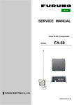
3.1.
i-ais-AN1 Electronic Interface
The definition of connectors for i-ais-AN1 is given below.
Revision 2.1
10
i-ais-AN1
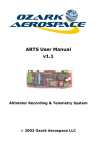
3.2.
Installation & User Manual
i-ais-AN1 Connectors
The top view of i-ais-AN1 connectors is as follows:
Revision 2.1
11
i-ais-AN1
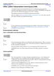
3.3.
Installation & User Manual
Basic Configuration
The basic configuration of the i-ais-AN1 is as follows.
The i-ais-AN1 can be configured with a special SW run on the PC connected to NMEA0 port.
Revision 2.1
12
i-ais-AN1
3.4.
Installation & User Manual
Mechanical Drawing of i-ais-AN1
Revision 2.1
13
i-ais-AN1
Installation & User Manual
4. Installation Guidelines
4.1.
i-ais-AN1 Installation Procedure
The i-ais-AN1 AIS AtoN equipment can be installed any flat surface with only three screws. The base
plate of the equipment is designed for an easy installation considering the harsh environments not
allow working long time.
After the fixing of screws, connection of antennas (VHF and GPS) and power cables is enough for a
basic AtoN operation.
The i-ais-AN1 should be installed and operated in a “Protected” environment as defined in IEC 60945
Section 4.4.
REMARK: For a proper operation, i-ais-AN1 should be installed with a VHF antenna which has a VSWR
value of 1.5:1 or better, with connecting RF cable.
4.2.
Antenna Installation Precautions
The antenna should be well removed from any major protrusions, such as buoy/light house rotating
beacon engine and antenna/conductor masts. It should also be as far as practical from gear doors,
access doors, or other openings that could affect its radiation pattern.
The antenna should be mounted on the maintenance ring of the buoy or light house barrier. Avoid
mounting the antenna within three feet of the any other communication antenna.
If the antenna is being installed on a composite buoy/light house, ground planes must sometimes be
added. Conductive wire mesh, radials, or thin aluminum sheets embedded in the composite material
provide the proper ground plane allowing the antenna pattern (gain) to be maximized for optimum
transponder performance.
The GPS antenna used must be of the active type and must be suitable for marine shipboard
applications (index of protection, ruggedness, means of mounting, etc.). An antenna should be
selected with a gain (in dB) depending on the length of cable between the antenna and the AtoN unit;
after subtraction of cable and connector losses a minimum total gain of 25 dB should be available at
the AtoN unit GPS antenna connector.
The GPS antenna used must be a dedicated antenna, i.e. not shared with any other GPS receiver.
Installation of the GPS antenna is critical for the performance of the built in GPS receiver which is used
for timing of the transmitted time slots.
The GPS antenna should be mounted in an elevated position and free of shadow effect from the
buoy/light house structure and should have a free view through 360 degrees with a vertical angle of 5
to 90 degrees above the horizon.
Revision 2.1
14
i-ais-AN1
Installation & User Manual
As the received GPS signal is very sensitive to noise and interference generated by other onboard
transmitters, ensure that antenna is placed as far away as possible from racon/radar transmitters and
ensure the GPS antenna is free from direct view of the racon/radar antenna beam. It is also important
that the MF/HF and other VHF transmitter antennas are kept as far away as possible from the antenna.
The VHF antenna should be a dedicated antenna, i.e. not shared with any other VHF
transmitter/receiver. It also should be suitable for marine buoy/light house applications (index of
protection, ruggedness, means of mounting, etc.)
The VHF antenna should be mounted with at least a two meter vertical separation distance from any
other VHF antenna used for speech or DCS communication, at least 2-3 meters above sea level for full
performance.
Connecting a badly mismatched VHF antenna, leaving the VHF antenna port disconnected, or shorting
the VHF antenna port will activate the VSWR alarm, cause the unit to stop sending position reports or
cause damage to the transponder.
To meet the requirements for Radio Frequency Exposure it is necessary to install the VHF antenna
correctly and operate the i-ais-AN1 equipment according to the instructions. The table below shows
suitable safety distances to other equipment that could cause interference with the AtoN
Transponder.
Object Safety distance:
Radar antenna, X-band
High efficiency engine
HF or VHF antennas
AC power cables with high currency
4.3.
1, 5 m (5 ft)
1 m (3 ft)
3 m (10 ft)
1 m (3 ft)
Cabling
The RF coaxial cables should be kept as short as possible to minimize attenuation of the signal.
Double shielded coaxial cables equal to or better than LMR200/LMR240 (for GPS) and LMR400
(for VHF) are recommended.
All outdoor connectors on the coaxial cables should be fitted with preventive isolation, such
as shrink-stocking with silicone to protect the antenna cable against water penetration.
Coaxial cables should be installed in separate signal cable channels/tubes, and at least 10 cm
away from any power supply cables. Crossing of cables should take place at right angles (90°).
Coaxial cables should not be exposed to sharp bends, which may lead to changes to the
characteristic impedance of the cable. The minimum bend radius should be 5 times the cables
outside diameter.
Revision 2.1
15
i-ais-AN1
4.4.
Installation & User Manual
Required Tools
The basic set of tools used during the installation of i-ais-AN1 is as given in the list below.
Screw drivers
Crimp tools
Utility knife
Socket Wrench Set
Wrench set
Hex Key Set
Wire cutters and strippers
4.5.
Installation Check Out
As the installation of i-ais-AN1 is completed, the following basic points should be checked as
an initial step, before the operational check out of the equipment:
12 -24 VDC Power connection
VHF Antenna connection
GPS Antenna connection
Revision 2.1
16
i-ais-AN1
Installation & User Manual
5. Post Installation Configuration
The i-ais-AN1 equipment shall be configured using a special interface software, “i-AIS NMEA Assistant”.
The assistant SW can be run on a PC connected through the NMEA0 port.
Besides the configuration of the equipment, the operational check of the equipment can be performed
using this SW.
Revision 2.1
17
i-ais-AN1
Installation & User Manual
6. Specifications
GENERAL
Operating Temperature Range
Storage Temperature Range
Humidity
Power Supply Voltage
Rated Fuse Current
-15ºC to +55º C
-30ºC to +70º C
Up to 93% at 40ºC non-condensing
12V – 24V DC (max 10V – 30V DC)
8A with slow burning fuse
Type-I (FATDMA only mode)
30mA nominal, 4A peak (during transmission) @ 12V
25mA nominal, 2A peak (during transmission) @ 24V
Supply Current
Type-III (RATDMA + FATDMA mode)
220mA nominal, 4A peak (during transmission) @ 12V
130mA nominal, 2A peak (during transmission) @ 24V
Power Consumption
(Type – I, FATDMA only mode Transmission of Msg 21 every 3
minutes in accordance with IEC
62320-2)
Size
Weight
Connectors
Case
Case IP Rating
TRANSMITTER
Operating Frequency Range
Channel Spacing
Transmitter Output Power
Modulation
RECEIVER (Type III only)
# of Receivers
Operating Frequency Range
Channel Spacing
Receiver Sensitivity
Co-Channel Rejection
Adjacent Channel Selectivity
Spurious Response Rejection
Intermodulation Response
Rejection
Blocking or Desensitization
Spurious Radiation (conducted)
Revision 2.1
< 0.8Ah/day @ 12V
152 mm x 174 mm x 146 mm
1.75kg
VHF Antenna: N Female
GPS Antenna: TNC Female
NMEA0, NMEA1, NMEA2, POWER, LANTERN, AC-RELAY:
Circular Plastic Connectors
AlMg0,5Si 6063
IP-66
156.025 – 162.025 MHz
25 kHz
12.5W (41dBm) nominal
2W (33dBm) low power mode
GMSK
2 (simultaneous operation)
156.025 – 162.025 MHz
25 kHz
Better than -107dBm
Better than 10 dB
> 70 dB
> 70 dB
> 65 dB
> 86 dB
< -57 dBm
18
i-ais-AN1
Installation & User Manual
STANDARDS
IEC 62320-2,
Maritime navigation and radiocommunication equipment
and systems – Automatic identification system (AIS) – Part
2: AIS AtoN Stations – Operational and performance
requirements, methods of testing and required test results
AIS
ITU-R M.1371-3,
Technical Characteristics for an Automatic Identification
System Using Time Division Multiple Access in the VHF
Maritime Mobile Band
IMO Res. MSC.74(69), Annex 3,
Recommendations on Performance Standards for a
Universal Shipborne Automatic Identification System (AIS)
EMC
Environment (Including vibration)
Safety
IALA Rec. A-126
The Use of the Automatic Identification System (AIS) in
Marine Aids to Navigation Services
ETSI EN 301 843-1
Electromagnetic compatibility and Radio spectrum
Matters (ERM);
Electromagnetic Compatibility (EMC)standard for marine
radio equipment and services; Part 1: Common technical
requirements
IEC 60945
Maritime navigation and radio communication equipment
and systems – General requirements – Methods of testing
and required test results
IEC 60950-1
Information Technology Equipment – Safety – Part 1:
General Requirements
APPROVALS
CE Type Approval per R&TTE Directive-99/5/EC
BSH, Statement of Conformity per IEC62320-2 & ITU-R M.1371-4
GPS RECEIVER
# of Channels
Time to First Fix
Receiver Sensitivity
Revision 2.1
16
29s Cold Start
29s Warm Start
<1s Hot Start
-160 dBm Tracking
-160 dBm Reacquisition
-144 dBm Cold Start
19
i-ais-AN1
Installation & User Manual
7. Approvals & Declaration of Conformity
Revision 2.1
20
i-ais-AN1
Revision 2.1
Installation & User Manual
21
i-ais-AN1
Revision 2.1
Installation & User Manual
22
i-ais-AN1
Installation & User Manual
8. Warranty Information
All iDeal products are warranted to be free from defects in materials or workmanship for one
year from the date of purchase. Within this period, iDeal Technologies, Inc. will, at its sole
option, repair or replace any components which fail in normal use. Such repairs or
replacement will be made at no charge to the customer for parts or labor, provided that the
customer shall be responsible for any transportation cost. This warranty does not cover
failures due to abuse, misuse, accident or unauthorized alterations or repairs.
Revision 2.1
23
i-ais-AN1
Installation & User Manual
9. Contact Information
iDeal Teknoloji Bilişim Çözümleri A.Ş.
Address:
Cumhuriyet Caddesi, Yeni Parseller Sokak, No: 20, B Blok
Kavacık / İstanbul – TÜRKİYE
e-mail:
[email protected]
Tel:
+90-216-680 07 07
Faks:
+90-216-680 07 04
Web:
http://www.idealteknoloji.com
Revision 2.1
24