1
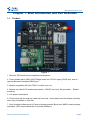
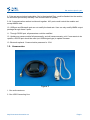
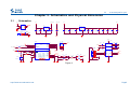
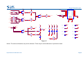
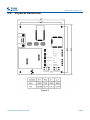
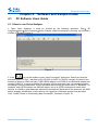
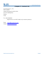
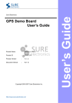
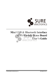
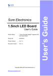
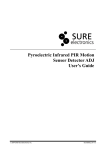
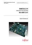
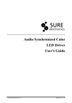
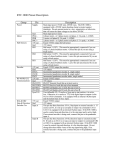
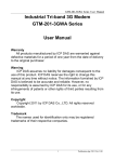
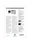
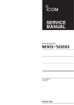
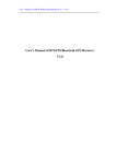
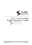
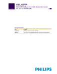
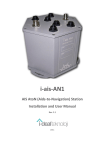
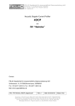
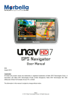
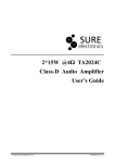
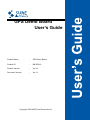
GPS Demo Board
User’s Guide
Product Name
: GPS Demo Board
Product ID
: DB-GP010
Product Version
: Ver 3.3
Document Version
: Ver 1.1
Copyright 2004-2007 Sure Electronics Inc.
Contents
We are here just for you!
Chapter 1. Brief Introduction and Port Definition ..............................2
1.1. Product ......................................................................................2
1.2. Accessories...............................................................................3
Chapter 2. Fast Guide...........................................................................4
Chapter 3. Schematics and Physical Dimension ...............................5
3.1
Schematics................................................................................5
3.2
Physical Dimension..................................................................7
Chapter 4. Software and Sample Codes .............................................8
4.1 PC Software Users Guide ........................................................8
4.1.1 How to use Orion Analyzer ..........................................................8
4.1.2 How to set baud rate .....................................................................9
4.2
Sample Codes..........................................................................11
Chapter 5. Contact US ........................................................................12
http://www.sure-electronics.net
Page1
We are here just for you!
Chapter 1. Brief Introduction and Port Definition
1.1. Product
Figure 1
1. Great for GPS based tools or appliance development.
2. Three useable ports, USB->UART Bridge based on CP2102, legacy RS232 port, and an
optional Bluetooth simulated RS232 port.
3. Module compatible with Ublx TIM-LC module in pin out.
4. Module use uNav 8130 baseband processor, 1008 RF front-end, 4th generation, -152dbm
sensitivity.
5. Low power consumption
6. Could locate with the antenna inside the room and 1 meter away from the window (normally
when over 6 satellites in view site).
7. Orion Analyzer software and U-Center software provided, Baud rate, NMEA output package
selectable. (GPS module baud rate is constant 9600bps.)
http://www.sure-electronics.net
Page2
We are here just for you!
8. Pulse per second signal selectable. (Not in the standard Rom, could be flashed into the module,
we would not provide any warranty if the module failed in update.)
9. All 3 communication method could work together. All 3 ports could control the module and
accept NMEA data.
10. USB port and Bluetooth port can not modify the baud rate. User can only modify NMEA output
package through these 2 ports.
11. Through RS232 port, all parameters could be modified.
12. Update may cause module fail permanently, and will cause warranty void. If user wants to do
update, a RS232 port should be used (not USB bridged type) to update firmware.
13. Bluetooth optional. Communication password is 1234.
1.2. Accessories
Figure 2
1. One active antenna
2. One USB Connecting Line
http://www.sure-electronics.net
Page3
+3.3V
Nema Output Busy
Updating Firmware
Pulse Per Second
+5V CMOS LEVEL
223
+5V
+3.3V CMOS LEVEL
223
223
223
223
223
223
Chapter 2. Fast Guide
We are here just for you!
+5V
GND
GPS_Dataout
+3.3V
GND
GPS_Dataout
GPS_Datain
Pulse Per Second
Press And Hold During Press For Reset
Firmware Upgrade
Figure 3
1.Connect the SMA connector of the Active antenna to the demo board and tie the screw (Shown
in Figure 1). Put the antenna to outdoor and keep the top side face the sky. The antenna has
integrated magnet, so it can be magnetized on any iron surface such like roof of your car. Try to
place it with a large viewable angle of the sky, if covering with any metal material, the signal would
be weak.
You could only use 3.3V type active antenna with this demo board, 5V active antenna will not work.
Keep the top of the antenna face the sky, or the signal may be too weak. Most active antennas are
anti water type, they could work in raining days.
2. Connect the USB->UART Bridge based on CP2102 to your host computer with the USB
connector. And tie miniusb to the demo board. Power your host computer and install the driver.
This GPS module is compatible with NMEA2.1 protocol, so it could work with most GPS software
that accepts NMEA protocol. For testing use, you could find Orion Analyzer software and u-center
evaluation software in the accessory CD. It is only for testing and studying use. We do not provide
any support on how to use Orion Analyzer and u-center, please view the user’s guide from Orion
Analyzer and u-center carefully. And notice don’t try update firmware with Orion Analyzer or
u-center, it may damage your module.
Your demo board should work after those steps, if you have any further questions, please refer to
the schematics and user’s guide carefully, and you could also email to
[email protected], we will try to solve all questions.
http://www.sure-electronics.net
Page4
Chapter 3. Schematics and Physical Dimension
Schematics
+5V
VCC_ANT
+5V
VCC_ANT
VCC
105
C6
C7
105
104
U2
CY T8117-3.3V
+ C2
+ C3
IN
OUT
100uF/16V
C8
22uF/16V tan
105
2
1
C9
+ C4
105
22uF/16V tan
C10
C11
C12
C13
C14
104
104
104
104
104
2
100uF/16V
3
2
1N5819
2
2
2
DJ005B D5
1
1
2
3
C5
OUT
GND
IN
1
U1
CY T8117-3.3V
1
3
2
USBRX
USBTX
5
6
7
8
+ C1
J2
e are here just for you!
CON8A
1
1
2
3
4
1
J1
GND
+5V
1
3.1
W
+5V
VCC
RFIN
VCC
PPS
BB
31
32
33
34
35
36
37
38
10
9
8
7
6
5
4
3
2
1
GPSTXD
GPSRXD
VCC
R9
10K
R12
DNI
1
VCC
S2
3
SWITCH
R10
DNI
R13
471
1
6
2
7
3
8
4
9
5
VCC
224
6
1
13
7
8
14
V+
C1+
C1C2+
V-
C2-
R1in
T2out
R1out
T2in
R2in
T1out
R2out
T1in
1
3
4
C15
2
224
1
C17
2
224
1
5
12
10
9
11
232RX
232TX
MAX3232
2
GND
RF_ON
IO3
RXD1
TXD1
TXD0
RXD0
GPIO15
GND
VCC
11
B+
11
S1
V_BAT
RESET
IO10
IO6
IO5
IO7
IO0
IO1
IO4
GND
4
SWITCH
3
21
22
23
24
25
26
27
28
29
30
C18
2
224
1
2
2
10K
J3
DB9
C16
2
VCC
16
U5
1
GND
ANT_PAD
15
14
13
12
11
10
GND
GND
GND
GND
GND
GND
GND
GND
GND
RF
B-
BAT1
R6
1
R7
270R
Li-ion/3V
GND
RF_IN
GND
V_ANTENNA
VCC_RF
SPI_SDI/IO12
SPI_SDO/IO13
SPI_SCK/IO14
SPI_XCS0
IO2
RTC_SDA/IO9
RTC_SCK/IO8
WAKEUP/IO11
1N5819
2
4
D6
1
2
VCC
Fuse_100mA
2
F1
VCC_ANT
16
17
18
19
20
HPM103H-6
5
4
3
2
RFIN
P1 SMA
15
GPS1
Figure 4
http://www.sure-electronics.net
Page5
We are here just for you!
VCC
3
1
USBTX
14
U3B
4
3
74HC04
7
74HC00
14
U4B
4
VCC
R8
10k
R11
10k
R14
10k
R15
10k
6
5
VCC
8
14
U3D
8
9
GL-6B
PIO(11)
PIO(10)
PIO(9)
PIO(8)
PIO(7)
PIO(6)
PIO(5)
PIO(4)
PIO(3)
PIO(2)
PIO(1)
PIO(0)
GND
34
33
32
31
30
29
28
27
26
25
24
23
22
14
15
16
17
18
19
20
21
9
10
74HC00
UART-TX
UART-RX
UART-CTS
UART-RTS
PCM-CLK
PCM-OUT
PCM-IN
PCM-SY NC
AIO(0)
AIO(1)
RESET
3.3V
GND
74HC04
7
74HC00
7
3V3TX
5VTX
U4C
10K
GPSRXD
74HC04
7
14
R20
VCC
U3C
6
5
1
2
3
4
5
6
7
8
9
10
11
12
13
GND
USB DSPI-CSB
SPI-MOSI
SPI-MISO
SPI-CLK
USB D+
GND
10k
BTTX
BTRX
14
R5
2
U4A
7
VCC
14
U6
7
232TX
VCC
BTTX
+5V
3V3RX
R3
R4
PAD
TP3
PAD
TP5
PAD
TP7
+5V
PAD
TP2
PAD
TP4
PAD
TP6
PAD
TP8
PAD
TP9
VCC
331
101
101
101
Q1
9014
10K
D1
D2
D3
D4
LED/G
LED/G
LED/R
LED/B
5VTX
3V3TX
R19
GPSRXD
101
5VRX
3V3RX
D7
7
74HC04
1
5VRX
1
101
2
U3F
12
13
TP1
2
R18
74HC00
R2
2
R17
14
7
R1
1
11
13
PAD
14
12
U4D
7
14
VCC
1K
74HC04
1
U3E
10
11
BTRX
2
USBRX
VCC
2
GPSTXD
VCC
R16
14
232RX
+5V
LED/Y
1
PPS
U3A
2
1
PPS
74HC04
7
VCC
Figure 5
Notice: The above schematics are just for reference. There may be a little difference in production batch.
http://www.sure-electronics.net
Page6
3.2
We are here just for you!
Physical Dimension
Figure 6
http://www.sure-electronics.net
Page7
We are here just for you!
Chapter 4. Software and Sample Codes
4.1
PC Software Users Guide
4.1.1 How to use Orion Analyzer
1. Open Orion Analyzer. It could be located by the following operation: Start
All
Programs uNav Orion Analyzer Orion Analyzer. When the program is running, you will see a
window as shown in Figure 9.
Figure 7
2. Click
icon on the toolbar to open “New Connection” dialog box. Select port from the
pull-down menu of “Port”. Interface built in RS-232 to UART is COM1-2 normally, but that built in
modem of laptop is COM3 normally. USB-RS232 adapter use COM3-8, and Bluetooth adapter will
occupy COM4-15. In some occasions the situation may be changed. User can choose right port
according to above presentation. Select right baud rate from the pull-down menu of “Baudrate”, for
example, most GPS modules use 4800 as default, but as to GPRS modules and some other
devices, it is 9600 or other baud rate adjusted by themselves. Baud rate of this product is set 9600
before shipping. Modification of this value is not suggested. Otherwise product may be failed.
Click “Create” button to finish setting New Connection. As shown in figure 10.
http://www.sure-electronics.net
Page8
We are here just for you!
Figure 8
If it has already connected to PC, you will see the port is opened in the bottom. After 1-5 minutes, you
will see a window as below.
Figure 9
3. You could refer to the user’s guide of Orion Analyzer for more information.
4. Every demo board was tested for 3 times before shipping. If it could not run, please make sure
that the connection is correct.
5. It can work with almost all navigation software, and its setting is similar to Orion Analyzer. You
could check the user’s manual of those software for more information.
4.1.2 How to set baud rate
Baud rate can be set via Orion Analyzer as to serial interface. Click
icon on the toolbar.
Then select “Output Configuration” from the pop-up dialog box to activate the pull-down menu of
baud rate. You can select right baud rate. Click “Sent” button. If the message box at the bottom of
http://www.sure-electronics.net
Page9
We are here just for you!
the window is said that “The message has been sent”, it means that baud rate has been set. Click
“Close” button to close this dialog box. If product can receive and send message normally, baud
rate has been modified successfully.
Figure 10
http://www.sure-electronics.net
Page10
We are here just for you!
Figure 11
Notice: Improper modifications maybe damage the product.
4.2
Sample Codes
N/A
http://www.sure-electronics.net
Page11
Chapter 5. Contact US
We are here just for you!
Sure Electronics Co., LTD.
Floor 4, A zone,
Qinhuai Technology Innovation center,
NO.105-2, DaMing Road,
Nanjing,
China
Tel: +86-25-66606340
(English service, from GMT1-10AM, only for technical questions)
Email:
[email protected]
Website: www.sure-electronics.net
http://www.sure-electronics.net
Page12