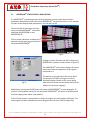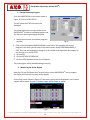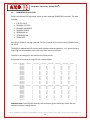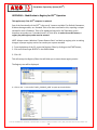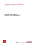
1
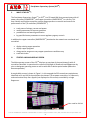
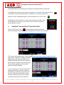
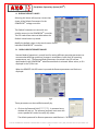
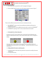
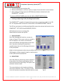
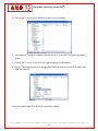
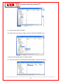
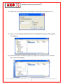
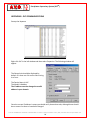
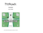
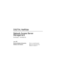
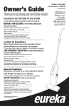
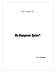
PRECIPITATOR SUPERVISORY SYSTEM PSStm 5146-G COMMERCE AVENUE MOORPARK CA 93021 (805) 531-8900 FAX (805) 531-8903 www.avcspecialists.com SPECIALISTS, INC. Precipitator Supervisory System (PSSTM) Table of Contents I. Notices and Installation Considerations ........................................................................................ 2 II. WHAT IS THE PSSTM? ............................................................................................................................ 4 III. STARTUP AND MAIN DISPLAY SCREEN ............................................................................................ 4 IV. POWERCONtm AND RAPPERCONtm MONITOR SCREENS .................................................................. 5 V. POWERCONtm (T/R SET) STATUS DISPLAY AND CONTROL .................................................................. 6 A. DISPLAY DEFAULT VALUES .............................................................................................................. 7 B. DISPLAY OR EDIT REMOTE VALUES ................................................................................................. 7 a. Selecting Default or Remote Operation ...................................................................................... 8 b. Editing Individual Parameters and Saving them .......................................................................... 8 c. Creating an Operating Profile, Recalling Stored Profiles ............................................................. 9 C. VIEW AVERAGES .............................................................................................................................. 9 D. VIEW STATUS ................................................................................................................................... 9 E. VIEW PRE‐TRIP ............................................................................................................................... 10 F. VIEW SUMMARY ............................................................................................................................ 10 G. VIEW LIMITS .................................................................................................................................. 10 VI. RAPPERCONtm STATUS DISPLAY AND CONTROL ............................................................................ 11 1. Change Operating Program ........................................................................................................... 12 2. Monitoring the Active Rapper ....................................................................................................... 12 VII. POWERCON STATUS LOGS ............................................................................................................ 13 APPENDIX A ‐ Modification to Registry for PSStm Operation ..................................................................... 14 APPENDIX B ‐ DCS COMMUNICATIONS ..................................................................................................... 18 APPENDIX C – SCHEMATICS....................................................................................................................... 20 5146-G COMMERCE AVENUE MOORPARK CA 93021 (805) 531-8900 FAX (805) 531-8903 www.avcspecialists.com 1 SPECIALISTS, INC. Precipitator Supervisory System (PSSTM) I. Notices and Installation Considerations Notices Danger During normal operation of this device, hazardous voltages are present which can cause severe injury or death. High voltages are present on the terminal blocks, circuit boards, power distribution and control devices. These voltages are present beyond the control enclosure in which this equipment is installed. Limitation of Liability A.V.C. Specialists, Inc. reserves the right to make changes in the devices or the device specifications identified in this Installation and Operating Manual without notice. A.V.C. Specialists advises customers to obtain the latest versions of device specification and operating firmware before installing this equipment. In the absence of written agreement to the contrary A.V.C. Specialists, Inc. assumes no liability for A.V.C. Specialists, Inc. applications assistance, customer’s system design, or infringement of patents or copyrights of third parties by or arising from the use of devices described herein. A.V.C. Specialists does not warrant or represent that any license, either expressed or implied, is granted under any patent right, copyright, or other intellectual property right of A.V.C. Specialists, Inc. covering any combination, machine, or process in which such device might be used. Except to the extent prohibited by applicable law, under no circumstances shall A.V.C. Specialists, Inc. be liable for consequential damages sustained in connection with said product. A.V.C. Specialists, Inc. neither assumes nor authorizes any representative or other person to assume for it any obligation or liability other than such as is expressly set forth herein. POWERCONtm, RAPPERCONtm, PRECIPITATOR SUPERVISORY SYSTEMtmt, PSStm and HOPPER HAMMERtm are trademarks of A.V.C. Specialists, Inc. All other trademarks are property of their respective owners. The information contained in this document is believed to be accurate at the time of publication, however, A.V.C. Specialists, Inc. assumes no responsibility for any errors that may appear here and reserves the right to make changes without notice. 5146-G COMMERCE AVENUE MOORPARK CA 93021 (805) 531-8900 FAX (805) 531-8903 www.avcspecialists.com 2 SPECIALISTS, INC. Precipitator Supervisory System (PSSTM) Installation and Maintenance Considerations Installation and maintenance of the POWERCONtm control and auxiliary equipment should only be performed by qualified, competent personnel that have appropriate training and experience with high-voltage and current devices. Every effort has been made to ensure the installation instructions presented in this document are clear and easy to understand; however, if you are not sure how to perform any of the instruction provided, DO NOT CONTINUE THE INSTALLATION, OPERATION OR REPAIR of this equipment. Warning Failure to observe the following information may result in severe injury or death. During normal operation of this device, hazardous voltages are present on the terminal strips, circuit boards, auxiliary equipment and external circuits. Follow standard safety precautions while performing any installation or service work. Warning This equipment should be installed in a switchgear cabinet or similar enclosure to ensure that the equipment is not accessible to non-qualified personnel. Do not use this device for primary protection functions. These include applications where the device performs energy limiting functions or provides protection of people from injury. Primary protective equipment includes but is not limited to circuit breakers, ground fault interrupters, fuses, etc. The POWERCONtm control may be used to provide secondary protection functions. Do not HIPOT/Dielectric test this equipment. Do not remove or install any circuit board with power applied to the control. The field devices operated by this equipment are often attached to equipment that operates at very high-voltages. Proper grounding of field devices is essential to provide protection of this equipment and service personnel. 5146-G COMMERCE AVENUE MOORPARK CA 93021 (805) 531-8900 FAX (805) 531-8903 www.avcspecialists.com 3 Precipitator Supervisory System (PSSTM) SPECIALISTS, INC. TM II. WHAT IS THE PSS ? The Precipitator Supervisory Systemtm (or PSStm) is a PC‐based HMI that communicates with all power controllers (POWERCONtm) and rapper controllers (RAPPERCONtm) in a facility. This user‐friendly and intuitive supervisor system allows operators to monitor and control the performance of the T/R controllers (POWERCONtm): track status of voltage, current and power modify parameters to improve operation provide alarm and warning notification log specified status parameters to meet regulatory agency controls In addition the rapper controllers (RAPPERCONtm) attached to the network are monitored and controlled: display existing rapper operation display rapper programs change active program to vary rapper operation as conditions vary track fault issues III. STARTUP AND MAIN DISPLAY SCREEN The Main operator screen of the PSSTM displays an overview of the precipitator(s) with all controllers identified. In operation this screen will highlight all Powercons and Rappercons by color to designate operating status as well as with text to advise special modes (Manual or Remote operation). A sample Main screen is shown in Figure 1. In this example the PSS controls two precipitators, identified as 1A and 1B. Each precipitator has sixteen T/R set power controllers, or Powercons, and one hundred forty‐four rappers (not displayed on this screen) controlled by a single Rappercon. Color code for STATUS Fig 1 5146-G COMMERCE AVENUE MOORPARK CA 93021 (805) 531-8900 FAX (805) 531-8903 www.avcspecialists.com 4 SPECIALISTS, INC. Precipitator Supervisory System (PSSTM) The RAPPERCON 1A and 1B programs and groups are displayed while in operation. In this figure two Powercons are shown in operation, 1A‐A1 and 1A‐A3. Powercon 1A‐A1 is displayed as dark red, signifying that the Powercon is running at a high limit. Powercon 1A‐A3 is displayed as green, alive and well but in an “OFF” state. The Rappercons also conform to a color code convention to make it easy for the operator to identify current status of each controller and know which rapper(s) is active. IV. POWERCONtm AND RAPPERCONtm MONITOR SCREENS Click on any T/R set in Unit 1A precipitator and the screen will focus the selected precipitator unit (the same goes for Unit 2A in our example). Fig 2 This is a very informative screen in that it displays the active state of every component of the precipitator. Powercontm voltage controllers, Rappercon(s), and individual rapper(s) are displayed to allow instant status recognition by the operator. Rappers are normally green if not actively rapping, red if active and yellow if in a fault condition. In our example sixteen T/R Sets (Powercontm voltage controllers) are shown, complete with address or identifier, color status and (as seen in Fig 2) a text identifier to show that two of the Powercons are in Manual mode (M for Manual and R for Remote). Fig 3 5146-G COMMERCE AVENUE MOORPARK CA 93021 (805) 531-8900 FAX (805) 531-8903 www.avcspecialists.com 5 SPECIALISTS, INC. Precipitator Supervisory System (PSSTM) Other conditions that appear are yellow, if the POWERCONtm is faulted for any reason, and blue if the POWERCONtm is currently running in Power Off Rapping (shown in Figure 3). V. POWERCONtm (T/R SET) STATUS DISPLAY AND CONTROL Once the individual precipitator unit is displayed, click on the T/R set icon ( ) to pop up the status display, and edit screens, for the selected POWERCONtm voltage controller. The main POWERCONtm screen is shown in Figure 4. This screen shows the instantaneous status values for the most important data as well as the operational status and any alarm that might be active. Fig 4 In addition, pushbuttons down the left side allow the operator to Start or Stop the controller, Clear or Ack(knowledge) warnings or alarms. Five blue pushbuttons across the bottom allow the: Display and editing of Default Parameters Display and editing of Remote Parameters View the 6 Minute Averaged variable data View pre‐trip data View overall status of the POWERCONtm View and edit limits View a summary of the status variables 5146-G COMMERCE AVENUE MOORPARK CA 93021 (805) 531-8900 FAX (805) 531-8903 www.avcspecialists.com 6 Precipitator Supervisory System (PSSTM) SPECIALISTS, INC. A. DISPLAY DEFAULT VALUES Selecting this button will pop‐up a screen that shows all the Default Parameters for the POWERCONtm voltage controller. The Default Parameters are stored in non‐ volatile memory in the POWERCONtm controller. The PSS reads these status variables when the Default Values button is pressed. Modify the default values via the touch screen of each individual POWERCONtm controller. Fig 5 B. DISPLAY OR EDIT REMOTE VALUES Remote Mode of operation is a useful tool for testing different operating parameters to accommodate differing conditions (changes in atmosphere, boiler fuels or operating temperatures, etc). The Remote Mode parameters are stored in the PSS and are downloaded to the POWERCONtm when Remote Mode is activated. When active, an R is displayed in the T/R Set icon. When the REMOTE VALUES button is pressed the Remote parameters and limits are displayed: Fig 6 These parameters can be modified manually by: Click on the Password field (*********). A password entry window will pop‐up. The operator/engineer must enter the correct password in order to modify any values. The default password for Remote parameter modification is “4170005”. 5146-G COMMERCE AVENUE MOORPARK CA 93021 (805) 531-8900 FAX (805) 531-8903 www.avcspecialists.com 7 Precipitator Supervisory System (PSSTM) SPECIALISTS, INC. Once the password is entered click on OK. The keypad will disappear. Click on CHANGE VALUES and the screen will change to appear as shown in Figure 7. Fig 7 There are three different primary functions that are accessed by this screen. The POWERCONtm can be run with the stored Remote variables by clicking on the Default/Remote button. Individual parameters can be modified and saved to disk or saved to the POWERCONtm. A POWERCONtm operating “Profile” can be created and saved and recalled. a. Selecting Default or Remote Operation At power‐on the PSStm assumes Default mode. Accessing the Remote Mode edit screen displays the Default/Remote button, which, based on which mode is active, will appear as follows: Pressing the AVC in Default Mode will cause the PSSTM to activate Remote Mode and download the Remote parameters to the POWERCONtm controller (these values are stored on the PSSTM). b. Editing Individual Parameters and Saving them 1. Clicking/pressing the value field of the parameter that you wish to modify will activate its edit mode. 2. The keypad will pop‐up. 5146-G COMMERCE AVENUE MOORPARK CA 93021 (805) 531-8900 FAX (805) 531-8903 www.avcspecialists.com 8 Precipitator Supervisory System (PSSTM) SPECIALISTS, INC. 3. Type the desired value and press OK. 4. Press the SAVE button. It will turn red for a couple of seconds while it saves the data. 5. After making all changes press the RSTR (Restore) button to download to the POWERCONtm controller. To return to DEFAULT MODE press the red AVCs In REMOTE MODE button. c. Creating an Operating Profile, Recalling Stored Profiles The POWERCONtm is capable of automatically generating an operating profile for the T/R Set. For complete details on how this is done refer to the POWERCON 900tm Manual. The PSS has two buttons in the Remote Mode Edit screen that activate the function in the POWERCONtm: GET PROFILE and GEN(ERATE) PROFILE. GET Profile will retrieve a stored profile. GEN Profile will create a new profile. C. VIEW AVERAGES Press View Averages will switch to a screen as shown in Figure 8. This screen is also very useful in that the operator can monitor instantaneous values and 6 Minute Averaged values at the same time. Very when checking for anomalies or sporadic events that can be affecting performance of the precipitator. Spikes in the instantaneous values may not affect the 6 Min Avg but still have negative impact on performance of the T/R Set and the precipitator. D. VIEW STATUS Press View Status to switch the screen to display a three‐column list of Status and Settings, Alarms and Communications Status flags. The system time and date is shown as well. This screen displays a color based round button next to any state that is true. If an alarm or fault occurs the operator can quickly view which was the cause. Fig 9 Fig 10 5146-G COMMERCE AVENUE MOORPARK CA 93021 (805) 531-8900 FAX (805) 531-8903 www.avcspecialists.com 9 Precipitator Supervisory System (PSSTM) SPECIALISTS, INC. E. VIEW PRE‐TRIP If a POWERCONtm should trip, for any reason, the values just prior to the trip are stored into registers for viewing and troubleshooting. The data set includes Primary Volts and Amps, Primary Power, Secondary kV and ma, Spark Rate and Phase Angle. In addition Fig 11 Fig 12 Fig 13 F. VIEW SUMMARY The Summary screen displays key instantaneous values for all POWERCONtm controllers in the precipitator unit. Values are either summed or averaged, depending on the nature of the data, across the bottom of the screen. G. VIEW LIMITS Pressing the VIEW LIMITS button will add the programmed limit values to the POWERCONtm main screen. This is very useful in that it allows the operator to view the current, instantaneous values against the set limits. If a specific T/R Set is continuously running at a high or low limit this screen will show which limit is causing the issue. 5146-G COMMERCE AVENUE MOORPARK CA 93021 (805) 531-8900 FAX (805) 531-8903 www.avcspecialists.com 10 Precipitator Supervisory System (PSSTM) SPECIALISTS, INC. VI. RAPPERCONtm STATUS DISPLAY AND CONTROL If a RAPPERCONtm is operating as part of the precipitator control system there will be a pushbutton identified with the name of the RAPPERCONtm on the main screen. In this example the main screen displays dual precipitators, Unit 1A and Unit 1B. On the left side of the screen note that there are two RAPPERCONtm controllers, identified as RAPPERCON 1A and RAPPERCON 1B. Click on either red button to display the operator monitor and control screen for the selected RAPPERCONtm. Fig 14 Fig 15 Clicking on either will cause the PSS to display the RAPPERCONtm operator screen, shown in Figure 15 The RAPPERCONtm main screen displays all the key information about the operation of the rappers connected to it. The buttons on the left side of the screen allow the operator to START running the currently selected Program (shown on this screen along with the active Group and the Board and Terminal address for the active rapper(s). Additionally, pressing the PAUSE button will cause the RAPPERCONtm to stop rapping for 12 minutes. If no keyboard activity for this period the RAPPERCONtm will return to operation and continue rapping from where it was paused. If the CLR clear button is pressed after a change of program the new program will begin. If no new program has been selected the current program will start over from the beginning. 5146-G COMMERCE AVENUE MOORPARK CA 93021 (805) 531-8900 FAX (805) 531-8903 www.avcspecialists.com 11 Precipitator Supervisory System (PSSTM) SPECIALISTS, INC. 1. Change Operating Program From the RAPPERCONtm main screen shown in Figure 15 click on VIEW STATUS. This will cause the STATUS screen to be displayed: This screen displays the current status of the RAPPERCONtm as well as available programs and any alarms or warning messages may exist. 1. Notice that there are six resident programs possible. Fig 16 2. Click on the field labeled RUN PROGRAM #, note that in this example the current program is #4, which you will note in the center section under PROGRAM NAMES, is POR_Test. Use the keyboard to change it to the number that represents the program to run next (ex: 5 to run OB‐TEST). 3. Click on SET. 4. Click on RETURN TO PREVIOUS 5. Click the STOP button and then the CLR button. The new program will be loaded and begin running. 2. Monitoring the Active Rapper Note the CH1 and CH2 Board and Terminal values. As the RAPPERCONtm runs a program the display will show the currently active rappers. On the Unit screen (shown in Figure 17) the active rappers will be displayed in red. Inactive rappers will be shown in green. A faulted rapper will be shown in yellow. Fig 17 5146-G COMMERCE AVENUE MOORPARK CA 93021 (805) 531-8900 FAX (805) 531-8903 www.avcspecialists.com 12 SPECIALISTS, INC. Precipitator Supervisory System (PSSTM) VII. POWERCON STATUS LOGS Every 6 minutes the PSS logs status values for each attached POWERCON controller. This data includes: IE DUTY CYCLE PRIMARY VOLTAGE PRIMARY AMPERAGE PRIMARY POWER SECONDARY KV SECONDARY Ma SPARK RATE Each day, at 12AM, a new log is started. The file is named for the current date (12162012=Dec 16, 2012). The logfile is updated every 6 minutes with the above referenced data in “csv” format for easy importing into spreadsheets, with each entry date and time stamped. The data is the average for the previous six minute period. An example of a section of a log (PSS #1) is shown below: 5/30/2012 7:57 FIELD NAME FIELD 1A‐A1 FIELD 1A‐A2 FIELD 1A‐A3 FIELD 1A‐A4 FIELD 1A‐B1 FIELD 1A‐B2 FIELD 1A‐B3 FIELD 1A‐B4 FIELD 1A‐C1 FIELD 1A‐C2 FIELD 1A‐C3 FIELD 1A‐C4 FIELD 1A‐D1 FIELD 1A‐D2 FIELD 1A‐D3 FIELD 1A‐D4 5/30/2012 8:03 FIELD NAME FIELD 1A‐A1 FIELD 1A‐A2 FIELD 1A‐A3 FIELD 1A‐A4 FIELD 1A‐B1 FIELD 1A‐B2 FIELD 1A‐B3 FIELD 1A‐B4 FIELD 1A‐C1 FIELD 1A‐C2 FIELD 1A‐C3 IE Duty Cycle Primary Volts 6 6 6 6 6 6 6 6 6 6 6 6 6 6 6 6 IE Duty Cycle Primary Amps 148 236 346 396 371 312 108 145 264 148 236 346 148 236 346 312 Primary Volts 6 6 6 6 6 6 6 6 6 6 6 206 239 339 107 146 265 396 371 239 339 107 Primary Power Secondary KV Secondary mA Spark Rate 13 1 25.5 34 21.6 4.7 38.5 118 61.2 20.4 51.5 320 20.9 6 60 96 17 5 59.5 91 20.2 5.9 59.5 86 5.8 0.7 23 15 12.2 0.9 25 31 37.2 8.7 38 180 13 1 25.5 34 21.6 4.7 38.5 118 61.2 20.4 51.5 320 13 1 25.5 34 21.6 4.7 38.5 118 61.2 20.4 51.5 320 20.2 5.9 59.5 86 Primary Amps Primary Power Secondary KV Secondary mA Spark Rate 20.8 3.9 36.5 90 22.1 4.9 39 121 59.2 19.2 50.5 307 5.6 0.6 23 14 12.4 0.9 25 32 37.5 8.8 38 181 20.8 6.1 60 96 17 5 59.5 91 22.1 4.9 39 121 59.2 19.2 50.5 307 5.6 0.6 23 14 Important note: The DATALOG directory will continue to grow indefinitely unless files are moved to another holding location. 16 20 4 0 0 0 29 15 2 16 20 4 16 20 4 0 20 20 10 29 16 1 0 0 20 10 29 5146-G COMMERCE AVENUE MOORPARK CA 93021 (805) 531-8900 FAX (805) 531-8903 www.avcspecialists.com 13 SPECIALISTS, INC. Precipitator Supervisory System (PSSTM) APPENDIX A ‐ Modification to Registry for PSStm Operation This applies only if the PSStm computer is replaced. Part of the functionality of the PSStm is the use of “common variables” for Default Parameters, 6 Minute Average values, etc. Standard Think n Do does not allow for this, requiring a unique variable for each I/O address. Think n Do added this feature for AVC Specialists, and is therefore not present on a "standard install" of Think & Do. In order to use this feature, a registry key and registry value must be created. NOTE: Always create a Windows "System Restore Point" and back up registry prior to making changes. Improper registry entries can render your system unusable. 1 ‐ From the desktop of the PC, access the Registry Editor by clicking on the START button, 2 ‐ Click on RUN and type REGEDIT in the RUN window 3 ‐ Click OK This will startup the Registry Editor that will allow you to create these registry entries. The Registry tree will be displayed: 4 – Click on the ‘+’ to the left of ‘HKEY_CURRENT_USER’ to open up the sub folders 5146-G COMMERCE AVENUE MOORPARK CA 93021 (805) 531-8900 FAX (805) 531-8903 www.avcspecialists.com 14 SPECIALISTS, INC. Precipitator Supervisory System (PSSTM) 5 – Click on the ‘+’ to the left of ‘Software’ to open up its sub‐folders 6 – Scroll down to ‘Think & Do Software’ and click on the ‘+’ to the left. This opens up the sub‐ folders. 7 – Click on the ‘+’ next to ‘Think & Do I/O View’ to open up its sub‐folders. 8 – Click on ‘Think & Do I/O View’ to highlight the folder and then click on the EDIT menu, then NEW and then KEY. A new sub‐folder under Think & Do I/O View will be created. 5146-G COMMERCE AVENUE MOORPARK CA 93021 (805) 531-8900 FAX (805) 531-8903 www.avcspecialists.com 15 SPECIALISTS, INC. Precipitator Supervisory System (PSSTM) 9 – Name the new folder ‘OPTIONS’ 10 – Right click on the ‘Options’ folder and click on NEW and DWORD Value A new item will be displayed in the Options folder. 11 ‐ Name this new item ‘EnableModbusMultiMapMode’ (without the quotes) 5146-G COMMERCE AVENUE MOORPARK CA 93021 (805) 531-8900 FAX (805) 531-8903 www.avcspecialists.com 16 SPECIALISTS, INC. Precipitator Supervisory System (PSSTM) 12 – Double click on this item to open a new window. Set the value for this new item to ‘1’. 13 – Enter a ‘1’ in the Value data field and click OK. The added data item value will be updated in the Registry. 14 ‐ You have successfully modified the Registry to support the new feature. Click on File and Exit to return to the desktop. 5146-G COMMERCE AVENUE MOORPARK CA 93021 (805) 531-8900 FAX (805) 531-8903 www.avcspecialists.com 17 SPECIALISTS, INC. Precipitator Supervisory System (PSSTM) APPENDIX B ‐ DCS COMMUNICATIONS Startup the Kepware Right click AVC in the left window and then select Properties. The following window will appear: The General tab should be displayed by default. If it does not click on the tab to bring it to front. The Device Name is AVC. The Model is Modbus. The IP address must be changed to a valid address in your domain. Once the correct IP address is setup you should verify these other tabs, although there should be no reason for them to have been changed. 5146-G COMMERCE AVENUE MOORPARK CA 93021 (805) 531-8900 FAX (805) 531-8903 www.avcspecialists.com 18 SPECIALISTS, INC. Precipitator Supervisory System (PSSTM) Most do not matter but be certain that the following settings are as shown: After verifying these settings click Apply and OK to return to the main screen. At this point the host should be able to access the Tag database on the Kepware system. The Tagnames are, by default, H00001 with properties and description in columns to the left. 5146-G COMMERCE AVENUE MOORPARK CA 93021 (805) 531-8900 FAX (805) 531-8903 www.avcspecialists.com 19 SPECIALISTS, INC. Precipitator Supervisory System (PSSTM) APPENDIX C – SCHEMATICS 5146-G COMMERCE AVENUE MOORPARK CA 93021 (805) 531-8900 FAX (805) 531-8903 www.avcspecialists.com 20