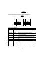
1
External & PCI/ISA card
External version
CORIOgen Eclipse
Release 2.1
DRAFT
Internal PCI/ISA version
User's Manual
Box indicates required cutting size.
PRINT MULTIPLE COPIES IN COLLATE MODE ONLY!
Out-line frame details:W: 15.70, H:20.80, D:4.62, L:2.62, cms.
Both versions
Discard this whole page and replace with front cover, and add rear cover.
Both versions
Internal PCI/ISA version
External version
Introduction
About this manual
Please note that this manual covers two versions of the CORIOgen Eclipse: the external
version, and the internal PCI/ISA card version. Whilst they share much of the internal
circuitry with each other, some control methods are not available on the internal card
version. Therefore, some parts of the manual may not apply to the version you have
bought. Side-tabs are used in the manual to highlight areas that apply to the internal
version, the external version, or both.
Features
The CORIOgen Eclipse provides high quality scan conversion (converting computer-type
video signals into television-type video signals), along with easy to use genlock and
overlay features. Its features and controllability make it the ideal method of overlaying
computer titles and graphics - for studio use, data/time overlay, presentations, video
titling and exhibitions.
The external unit is controllable via the on-screen display and push-buttons, infra-red
remote control or directly by a computer's RS232 port - so all features can be easily
accessed. The internal unit is limited to RS232 as standard, as it is intended mostly for
system integration - infra-red control is possible with an optional Infra-Red Receiver
Module. All settings can also be stored in non-volatile memory, and the external version
also features button-lock and Microsoft® serial mouse emulation.
For use in conjunction with other video equipment, the unit's built-in synchronization
(genlock) ability also means it can lock to an external video signal. Fine tuning of the
subcarrier phase adjustment is also possible.
This manual outlines the many features of the CORIOgen Eclipse, how to use them, and
how to get the best out of them. The different control methods are explained to allow you
to choose the most appropriate for your own uses.
Credits
CORIOgen Eclipse hardware and software ©1997-2000 Vine Micros Ltd.
Vine Micros Ltd, Vine House, Continental Approach,
Westwood Industrial Estate, Margate, Kent, CT9 4JG. UK.
Telephone: 01843 873300
Int: +44 1843 873300
Fax:
Int: +44 1843 873301
01843 873301
Internet web-site address: http://www.vinemicros.com
email: [email protected]
Designed and Manufactured in the United Kingdom.
Hardware and internal software designed by: R.P.D. Mallett and A.W. White B.Eng
AMIEE.
CORIOgen Eclipse instructions release 2.0 (c) December 2000. Written by R.P.D.
Mallett.
CORIO is a registered trademark of Vine Micros Ltd.
Disclaimer
No warranty is made either expressed or implied including but not limited to any implied
warranties of merchantability or fitness for a particular purpose. In no event shall Vine
Micros Ltd or any supplier of this product be liable for errors found within, or be liable
for any direct indirect or consequential damages or loss in connection with the purchase
or use of this hardware software or manual. The sole and exclusive liability to Vine
Micros Ltd regardless of the form of action shall not exceed the replacement cost of this
product.
By using this product you have indicated that you have agreed to the terms listed above.
If you do not wish to agree or the above terms are contrary to your conditions of purchase
you may return the complete package unused to your supplier.
All trademarks and copyrights are acknowledged. E&OE.
Important
The CORIOgen Eclipse has many unique
features and operating methods, and because
of this it is important that the user acquaints
his/herself with the operating instructions
that follow the hardware sections.
Without doing so, the full potential of the
unit may not be utilized.
Contents
Hardware Checklist (external version)
1
Hardware Setup (external version)
2
Connecting the CORIOgen Eclipse to a computer and monitor
2
Connecting the video outputs
2
Connecting the video input (for Genlock , Overlay, or Mix functions)
3
Connecting the serial cable (optional)
3
Connecting a mains adaptor
3
When you first turn on
3
Front-Panel Control (external version)
4
Control methods
4
Illuminated buttons
4
Sounder
5
Special button usage on Power-up
5
Special multi-hold buttons
5
Hardware Checklist (internal version)
6
Hardware Installation (internal version)
7
Preventing static damage to your card and PC
7
CORIOgen Eclipse PCI/ISA dual format
7
Installation of the card in a PC
8
Cable connections - PCI format
9
Cable connections - ISA format
10
Connecting the VGA Y-Splitter cable
10
Connecting the Video Breakout cable
10
Video Inputs (for Genlock , Overlay, or Mix functions) - marked '1' on each
connector
11
Video Outputs - marked '2' on each connector
11
Connecting the serial cable
11
When you first turn on
11
Reset switch (internal version)
13
Performing a Factory Reset
13
NTSC selection
13
Infra-Red Remote Control
14
Introduction
14
For external version...
14
For internal PCI/ISA version...
14
What this section covers
14
RESET
15
STORE
15
U.SCAN / O.SCAN
15
FREEZE
15
AUTOSET
15
FILTER
16
SIZE & POS
17
ZOOM
17
MODE (Overlay mode)
17
KEY
18
FADE
18
LOCK - External version only.
18
LEVEL
19
How to do a 'manual set'
19
On-Screen Display
21
Introduction
21
Activating & Navigating the On-Screen Display (OSD)
21
Flicker Red.
21
Auto Set
22
Overlay...
22
Signal Type - selecting the video input
22
Mode
22
Keyer
22
Key Level
23
Fade Speed
23
SC Phase
24
Exit
24
Screen Size...
24
Out H-Centre - altering the display's horizontal screen position
24
Out H-Width - altering the display's width
24
Out V-Centre - altering the display's vertical screen position
24
Out V-Height - altering the display's height
24
Exit
25
Manual Set...
25
VGA Left
25
VGA Width
25
VGA Top
25
VGA Bot (bottom)
25
VGA Store
25
Exit
25
Advanced...
Advanced Menu
Advanced...
25
26
26
Video Standard - PAL/NTSC
26
Sense - for AutoSet function
26
Brightness
26
RGB Term. - Input impedance
27
RS232 - Control/Mouse
27
Baud rate - for RS232 control
27
RS232 ID
28
Sound - on/off
28
IR (Infra-red) - on/off
28
Sync Out - comp. sync polarity
28
Disp Credits (internal PCI/ISA version only)
29
Total Lines - information
29
Vert Freq - information
29
Exit
29
RS232 Control
30
Setup
30
Sending commands
30
Responses to commands
30
Notes on sending commands
30
Restricting RS232 commands to certain units
31
Changing Baud Rates
31
Using Genlock, Overlay, and Mix
35
Basic functional diagram of the overlay circuit
35
Advantages of this circuit
35
Keyer circuit
35
Overlay mode function
36
Overlay mode in everyday use
37
Use with a monochrome composite video source
37
Use with RGB Out
37
Limitations of the genlock circuit
38
Mouse Emulation (external version)
39
Introduction
39
Hardware setup
39
CORIOgen Eclipse setup
39
Using the mouse emulator
39
Toggling Zoom/Pan and Mouse modes
40
Warranty & Returns Procedure
41
Warranty
41
Are you sure there's a fault?
41
To return a unit for repair
41
Technical Support
42
Internet / E-mail support
42
Telephone support
42
FAX support
42
Appendix A - Get the most from your unit
Hints & Tips
Appendix B - Troubleshooting
43
43
45
The picture on the video display is black and white
45
There is no picture on my video monitor
45
The picture on my video monitor is unstable or blank
45
There is no picture on the computer monitor
45
The display on the video monitor has a huge border around it
45
The unit does not respond to the Infra-red remote control
46
There is excessive flicker on the video monitor
46
The video monitor image is distorted
46
Some colours come out incorrectly on the video monitor
46
How can I reduce smearing?
46
How do I use the unit with a VCR?
47
Why don't I get better VHS recordings when using a SCART lead?
47
The recorded image is poor
47
The mouse emulation isn't working
47
Genlocking is unstable
47
Unit will not lock up to an external source
47
I get random colours on screen when overlaying or mixing
48
Appendix C - Technical Specifications
Input - from computer video card
49
49
Signals
49
Resolutions
49
Outputs - to video monitors, etc.
50
Signals
50
Image Scaling & Positioning
51
Control Methods
51
RS232 wiring
52
Sub-carrier lock & sync pulses
52
Genlock Overlay circuit
52
Power requirements - external version
52
Power requirements - internal PCI/ISA version
53
Colour sub-carrier frequency adjustments
54
European EMC 'CE' mark statement
55
EMC standards applied & passed
55
Grounding
55
FCC statement
56
External version
FADE
MODE
FREEZE +
O/SCAN -
MENU
Hardware Checklist (external version)
Infra-red receiver
Your package should contain:
CORIOgen Eclipse unit (as pictured above).
PC Monitor Cable.
Composite Video Lead.
S-Video Lead.
RC04 Remote Control with two AAA batteries.
CORIOgen Eclipse Instruction Manual.
Mains Adaptor - if you have not purchased a mains adaptor with this unit please
see the 'Technical Specifications' section for the appropriate type.
1
External version
Hardware Setup (external version)
We recommend switching off all equipment before starting the setup.
Connecting the CORIOgen Eclipse to a computer and monitor
Disconnect the monitor from the computer at the computer's video output. Connect this
cable to the 'PC OUT' socket on the back of the CORIOgen Eclipse. Apple Macintosh
computers may require an additional cable. This will let you see the monitor as before,
even when there is no power to the CORIOgen Eclipse.
Use the supplied computer-to-unit (15 pin to 15 pin) cable to connect the CORIOgen
Eclipse to the computer monitor output. Apple Macintosh computers may require an
additional cable. Connect this to the 'PC IN' socket on the back of the CORIOgen
Eclipse and to the monitor output on the computer.
RS232
PC In
PC Out Composite S-Video
In Out
In
RGB Out
Out
Power
Rear of CORIOgen Eclipse showing connectors
Connecting the video outputs
The CORIOgen Eclipse provides three different output types to allow connection to
various video displays and capture equipment (such as TVs and VCRs). The choice of
output type depends on what your equipment can accept.
Composite Video - use the composite video lead provided to connect from the
composite video output on the back of the CORIOgen Eclipse to the composite
video input of your target video equipment - eg. video monitor, TV, VCR, etc..
S-Video - use the S-Video lead provided to connect from the S-Video output on
the back of the CORIOgen Eclipse to the S-Video input of your target video
equipment. S-Video provides improved performance over Composite Video.
RGB / SCART connection. Most European TVs and Video recorders use this
connection, and the cable for this is optional. Connect the SCART cable to your
TV or video, and the 15-pin HiD plug into the correct connector on the back of
2
Connecting the video input (for Genlock , Overlay, or Mix functions)
The CORIOgen Eclipse has the ability to synchronize its video output with another video
signal (called 'genlocking'), or it can even superimpose its video output on top of another
video signal (called 'overlay' or 'mix'). This is done by connecting a video signal to one
of the CORIOgen Eclipse's inputs, and selecting the appropriate genlock/overlay setting
(see later in the manual).
Feed your video signal (if you want to genlock or overlay) into either the Composite
Video IN or S-Video IN connectors. You should also ensure that the signal used is of the
right standard (PAL/NTSC), and that it is a clean, stable, standard signal. Video signals
with a lot of noise, tape 'drop-out', or glitches may not be suitable - you will be likely to
get poor performance with such a video input.
Connecting the serial cable (optional)
The CORIOgen Eclipse can be controlled from a computer, and used as a remote
Microsoft® serial mouse emulator by connecting its RS232 port to a computer's RS232
port. See the sections on 'Mouse Control' and 'RS232 Control' later in this manual on
how to use these features.
Connecting a mains adaptor
The CORIOgen Eclipse requires a 12v DC (minimum 350mA) power supply - see
'Technical Specifications' for further information on suitable power supplies. Plug the
mains adaptor into a mains outlet and switch on at the mains outlet.
When you first turn on
Make sure that all leads are connected and that all other equipment is turned on - your
computer monitor should be functioning normally. Select the correct line input (AUX or
AV channel) on the target video equipment. The TV should now be displaying the same
picture as is on the computer monitor.
When the CORIOgen Eclipse is switched on, the green LED indicator on the front
panel will illuminate and the OSD (on-screen display) will display the version and
copyright details. If this does not happen refer to the troubleshooting section.
If there is a picture on the video monitor, but it is the wrong shape, position or
colour it may be necessary to alter some of the status settings before a good picture
is displayed. For example: it may be necessary to switch to PAL or NTSC
settings. Further details on selecting the correct settings for your display follows
in the Advanced Features section.
If there is no picture on the video monitor then go to the troubleshooting section.
3
External version
the CORIOgen Eclipse. For a VCR, this is equivalent to connecting using
composite video, since a VCR cannot use RGB signals.
Control methods
There are 3 ways to control the CORIOgen Eclipse:
1. By the buttons on the front panel
2. By the infra-red remote control unit
3. Directly from the computer via the serial (RS232) port
This section will describe what you can do with the 'quick-set' buttons on the front,
which are detailed at the bottom of the front-panel. The text at the top of the panel refers
to use when the on-screen display (OSD) menu is enabled when the MENU button is
pressed - and this, along with the infra-red and serial port control, is described later. The
text at the bottom of the panel refers to the 'quick-set' buttons detailed here.
FADE
MODE
FREEZE +
O/SCAN -
Shown below is a diagram that indicates the main features of the front panel.
MENU
External version
Front-Panel Control (external version)
Infra-red receiver
Front of CORIOgen Eclipse showing panel buttons
Illuminated buttons
These indicate the current state of the unit, and are also used to change the unit's state.
MENU. This is used to initiate front panel control of the unit via the on-screen
display (OSD), and to select the various options and features to change, and is
described in a later section. It illuminates green when power is on, and flashes if
a button or infra-red lock is active.
O/SCAN -. This enables and disables overscan mode - see the next section for
more details on what 'overscan' is. The button is illuminated when overscan is
selected.
4
MODE. This button cycles through the genlock and overlay modes available. It
illuminates whenever genlock or overlay is active. You should select the right
Signal Type before using this button (see On-Screen Display section).
FADE. This button will fade the converted computer signal in and out, and
flashes red when faded out.
Sounder
An internal sounder (buzzer) is used to confirm that a setting has changed with the
buttons, or to indicate that the CORIOgen Eclipse is saving settings to non-volatile
memory. You will hear it a fair bit during normal use, but it can be disabled if needed.
Special button usage on Power-up
Certain buttons can be held down when applying power to the unit, to perform certain
special functions:
Factory Reset. Hold down both the O/SCAN and FREEZE buttons when turning
the unit on. This will reset the unit to Factory settings (and set the unit into PAL
video mode). It should only be used if the unit's settings give an invalid output
that the user cannot exit from, as all user-settings will be erased by this.
Set to NTSC mode. This is done by holding the O/SCAN button down when
turning on the unit. This changes the non-volatile PAL/NTSC setting to NTSC,
and will be remembered even when power is removed.
Set to PAL mode. This is done by holding the FREEZE button down when
turning on the unit. This changes the non-volatile PAL/NTSC setting to PAL,
and will be remembered even when power is removed.
Special multi-hold buttons
Certain buttons can be held together when the unit is on to perform other functions.
Store Current Settings. This is done by holding the MENU and FREEZE
buttons in together for about 2 seconds, and can be done at any time. This stores
the current settings (e.g. Overscan, Overlay mode, etc.) in Non-Volatile Memory,
which will be read back the next time the unit is turned on.
This option will emit a high-pitched beep when complete to indicate that data has been
successfully stored. If you manage to store an invalid setting, you may need to do a
Factory reset (see above).
If you hear high pitch beeps at other times, it indicates that other data is being stored into
memory - eg. information the CORIOgen Eclipse has deduced about the graphics
resolution coming from your computer, such as when you change your screen resolution.
5
External version
FREEZE +. This button freezes the converted computer signal. The button
flashes when active.
Hardware Checklist (internal version)
Your package should contain:.
CORIOgen Eclipse PCI/ISA card with white support pillar attached.
PC Monitor Y-splitter Cable.
Video Breakout Cable (with 2 x composite video, 2 x S-Video, and 1 x
RGB/SCART connections).
5-Pin mini-DIN to 9-way RS232 Cable.
CORIOgen Eclipse Instruction Manual.
Internal PCI/ISA version
Please note that this unit gets its power from a spare hard-drive connector cable
within the PC. If you do not have a spare connection, you will need to use an
optional hard-drive connector Y-splitter cable.
If you wish to use the Infra-red control features of the units, you will also need:
Infra-Red Receiver Module.
RC04 Infra-Red Remote Control Handset.
(These items are not supplied as standard, as they will normally only be used once during
the card's initial setup. Therefore a single Receiver Module & Remote Control can be
used on multiple CORIOgen Eclipse PCI/ISA cards.)
6
Hardware Installation (internal version)
Preventing static damage to your card and PC
The CORIOgen Eclipse card is an electronic circuit, and as such is susceptible to static
damage. To minimise the risk it should be handled by the edges only, and care should be
taken that you don't touch the board's circuitry. Leave the card in the Anti-Static
packaging until you are ready to install it in your computer.
Your PC is also susceptible to static damage, so follow the PC manufacturer's guidelines
for installing an internal card. Never touch the internal components on the circuit board
of the PC unless directed to. Seek help from your PC supplier if you are at all unsure
about what to do.
This card can be altered to be either PCI or ISA format, simply by undoing the four
'hex-nuts' holding the back-plate to the 15-pin HiD connections, rotating the back-plate
180 degrees, and securely replacing the 4 'hex-nuts'.
In the diagram below, the PCI format is shown in detail.
The actual look, and therefore the connections, will be different depending on which way
round the back-plate is. The diagrams that follow will help to determine which way your
card is configured.
7
Internal PCI/ISA version
CORIOgen Eclipse PCI/ISA dual format
Holes
HD Power
Connector
Pillar
Pins
CORIOgen Eclipse in ISA configuration
Pins
Pillar
HD Power
Connector
Internal PCI/ISA version
Holes
CORIOgen Eclipse in PCI configuration
Installation of the card in a PC
Please note: if you are at all unsure about how to install a card into your PC, seek help
from your PC retailer or supplier.
Follow the steps below carefully. Vine Micros' warranty does not cover badly installed
cards.
1. Ensure your PC is turned off and unplugged at the mains.
2. Disconnect all cables from the PC.
3. Remove the cover of the PC - take care not to lose any screws.
4. Check that there is a spare 4-pin 'Hard-drive' power connector fly-lead - as used
to power hard disk drives and CD ROM drives. This may be secured with a
cable-tie, and will therefore require loosening. If no spare fly-lead is found, you
will need to use a Y-splitter to split the power cable into two (not included).
5. Locate a spare slot to take either a PCI or an ISA card according to the format of
the CORIOgen Eclipse card, and check that the Hard-drive power connector
fly-lead will reach the slot's position. You may need to reconsider the slot to
install into depending on the length of this power fly-lead.
6. Remove the blanking plate and securing screw from that slot position.
7. Carefully insert the CORIOgen Eclipse card into the required slot, and replace
the screw that has been removed in step 6.
8
8. Check that the card is secure, will not move, and that any neighbouring cards
will not touch the CORIOgen Eclipse card (and vice-versa) even if they move
slightly.
9. Connect the Hard-drive power connector fly-lead to the CORIOgen Eclipse
card.
10. Replace the cover of the PC.
11. Reconnect all normal cables, and see the next section on how to wire up the
card.
Cable connections - PCI format
RS232
TX/RX
Reset
switch
RGB/SCART
Output
Plug
1 2
PC Out
1 2
PC's VGA output
CORIOgen Eclipse card
See the next page for ISA format connections.
9
CV Input
CV Output
SV Input
SV Output
Internal PCI/ISA version
NB: Cables not shown to scale
Socket
Cable connections - ISA format
RGB/SCART
Output
1 2
PC Out
1 2
Plug
Internal PCI/ISA version
Reset
switch
CV Input
CV Output
SV Input
SV Output
RS232
TX/RX
Socket
NB: Cables not shown to scale
PC's VGA output
CORIOgen Eclipse card
See the previous page for PCI format connections.
Connecting the VGA Y-Splitter cable
It is recommended to do this with the PC still turned off.
1. Plug the 15-pin Hi-D plug on the Y-Splitter cable (there's only one) into your
graphic card's output connector.
2. Your monitor can then be connected to the PC Out connector on the Y-Splitter
cable - which is the shorter cable with the 'hex-nuts' on it.
3. Connect the remaining 15-pin in-line 'socket' connector to the appropriate
connector on the CORIOgen Eclipse card (only one will fit).
Because the Y-Splitter cable is so short it should not degrade the video performance of
your graphic card.
Connecting the Video Breakout cable
This cable plugs into the 15-pin Hi-D socket on the CORIOgen Eclipse card, to provide a
multitude of video inputs and outputs.
10
Video Inputs (for Genlock , Overlay, or Mix functions) - marked '1' on each
connector
The CORIOgen Eclipse has the ability to synchronize its video output with another video
signal (called 'genlocking'), or it can even superimpose its video output on top of another
video signal (called 'overlay' or 'mix'). This is done by connecting a video signal to one
of the CORIOgen Eclipse's inputs, and selecting the appropriate genlock/overlay setting
(see later in the manual).
Video Outputs - marked '2' on each connector
The CORIOgen Eclipse provides three different output types to allow connection to
various video displays and capture equipment (such as TVs and VCRs). The choice of
output type depends on what your equipment can accept.
Composite Video - use the composite video lead provided to connect from the
composite video output (2) on the breakout cable to the composite video input of
your target video equipment - eg. video monitor, TV, VCR, etc..
S-Video - use the S-Video lead provided to connect from the S-Video output (2)
on the breakout cable to the S-Video input of your target video equipment.
S-Video provides improved performance over Composite Video.
RGB / SCART connection. Most European TVs and Video recorders use this
connection, and the cable for this is optional - use a SCART plug to SCART plug
lead, with all pins connected. For a VCR, this is equivalent to connecting using
composite video, since a VCR cannot use RGB signals.
Connecting the serial cable
The CORIOgen Eclipse PCI/ISA card needs to be controlled from the computer's RS232
port - or you will not be able to select many of the unit's functions. Alternatively, you
can use the optional Infra-Red Receiver Module in combination with the RC04 remote
control.
When you first turn on
Make sure that all leads are connected and that all other equipment is turned on - your
computer monitor should be functioning normally. Select the correct line input (AUX or
AV channel) on the target video equipment. The video display should now show the
same picture as is on the computer monitor.
If there is a picture on the video monitor, but it is the wrong shape, position or
colour it may be necessary to alter some of the status settings before a good picture
11
Internal PCI/ISA version
If you want to use this ability, feed your video signal into either the Composite Video IN
or S-Video IN connectors (both marked '1'). You should also ensure that the signal used
is of the right standard (PAL/NTSC), and that it is a clean, stable, standard signal.
Video signals with a lot of noise, tape 'drop-out', or glitches may not be suitable - you
will be likely to get poor performance with such a video signal.
is displayed. For example, it may be necessary to switch to PAL or NTSC
settings. Further details on selecting the correct settings for your display follows
in the RS232 Control section.
Internal PCI/ISA version
If there is no picture on the video monitor then go to the troubleshooting section.
12
Reset switch (internal version)
Reset switch activation.
Performing a Factory Reset
1. Close down & turn off your computer.
2. Locate the micro-switch as shown in the diagram above.
3. Using a very small screwdriver, gently hold down the lever in the direction
shown in the diagram above.
4. Power-up the computer.
5. Release the micro-switch's lever about 1 second after turning on the computer.
Factory reset only occurs if the micro-switch is activated whilst the computer is being
turned on - it will not occur at any other time.
(Pressing the micro-switch emulates the depression of both the + and - buttons on the
external version of the CORIOgen Eclipse.)
NTSC selection
When doing a Factory Reset, you also change the unit to work in PAL. If you require it
to operate in NTSC, you will need to use the RS232 Control method to select NTSC
mode, and then do a 'Store Settings' so that it is used in the future.
Alternatively, if you have the Infra-Red Receiver Module, you can select NTSC from the
Advanced menu using the on-screen display.
13
Internal PCI/ISA version
A reset switch is viewable beside the 5-pin mini-DIN connector on the back-plate of the
card. It is a small micro-switch, and allows the user to restore the unit to Factory
Settings. This may be necessary if moving the card from one PC to another (eg. if the
RS232 baud rate is different, and you want to reset it to the default of 9600 baud).
Infra-Red Remote Control
Introduction
By now you should have the unit powered up and working with
your computer and TV. If you don't get an image on your TV,
please refer to the Troubleshooting section at the back of this
manual.
This unit has been designed for ease of use, and you should find
most of the controls simple to understand and apply.
RESET
1
3
MODE
KEY
FADE
AUTOSET
LEVEL
LOCK
SIZE
For external version...
L.CLICK
If at any time you find that the remote control or front-panel
buttons are not working, then you may have inadvertently
pressed the LOCK button on the remote control. Lock mode is
indicated by the green power button on the unit flashing - see
later for a description of how to turn this feature on and off.
STORE
2
POS
FILTER
D.CLICK R.CLICK
MOUSE
PAN
ZOOM
U.SCAN FREEZE
O.SCAN
For internal PCI/ISA version...
Remote Control RC04
The Infra-Red Remote Control is not supplied as standard with
the internal version. If you have purchased the Infra-Red
Receiver Module, its lead can plug into the internal card's 5-pin
mini-DIN (RS232) connector. You can then use the correct
remote control (optional) by aiming it at the Infra-Red Receiver
Module, to control the internal card.
In any case, this section contains information detailing each
function of the unit, and will therefore be needed even if you use
RS232 control.
What this section covers
Both versions
All the infra-red remote control features of the CORIOgen Eclipse.
It explains the setup and adjustments for the unit and what effect they have on the
final image.
How to store the settings so they are remembered by the unit for next time.
Therefore the following is required reading!
14
RESET
As its name implies, this resets the unit back to the last-saved user settings. It is useful if
you want to clear any changes made to screen size or position. If you've saved an invalid
setting to the non-volatile memory, you may want to do a Factory Reset - as described in
the Front Panel Button section.
STORE
This button is used for saving new settings to the unit's memory and will be remembered
even after the unit has been switched off. Just about all feature settings can be saved even Zoom mode and position. Note that Button Lock can be saved, but Remote Control
Lock cannot.
A high-pitched beep will be heard when this function is complete.
U.SCAN / O.SCAN
(Underscan / Overscan.) Pressing this button will toggle you between Underscan and
Overscan modes.
Underscan (sometimes known as Compress mode) will leave a border around your
image.
Overscan has no border and the displayed image (when set correctly) is larger
than your TV monitor screen.
This function is also available via the front-panel button labelled 'O/SCAN'.
The position and size of the image in both modes is user-adjustable, and the method of
doing so will be described later under the SIZE and POS functions.
FREEZE
The Freeze function allows you to freeze the current image on the screen, and most of the
settings of the unit itself. Pressing the freeze button again will unfreeze the image.
No other features are accessible whilst in Freeze mode, with the exception of RESET,
MODE and FADE. These functions are also available via the front-panel buttons of the
same name.
AUTOSET
This is a powerful feature of the CORIOgen Eclipse unit. Once activated this feature will
scan the incoming computer image to determine its size and position - thus optimising it
for display on the desired TV unit.
15
Both versions
Note that the freeze function will only freeze the image on the T.V monitor - the image
on the computer monitor will not be affected by this function and will carry on displaying
images as normal.
When your unit first encounters a new screen resolution or refresh rate, it will make a
guess on how best to display this on a TV. Sometimes, the guess needs 'refining', and
this function makes the unit itself search for the image edges to improve on this.
Until you run this feature (assuming you have not previously done so), the unit
will have 'guessed' the right settings in order to give a video output that is centred
and sized correctly. This 'first guess' is exactly that: a guess - as graphics cards in
computers have very few 'standard' resolution/refresh rate settings, and all other
settings vary drastically from computer to computer.
This feature requires that the top, bottom, left and right edges are of a certain
minimum brightness - i.e. certainly not black, but the actual level can be adjusted
and the method to do so is described later. Almost all Windows programs will
use the full size of the display which is fine, but some DOS programs (especially
at the DOS prompt) may not do so which will cause a problem for the unit.
Only use this feature when the full area of the computer screen is being used - this
will ensure that the unit 'sees' the edges correctly, and performs its task without
errors.
If you have a problem, a 'Manual Set' mode is available to fine tune the values
created by this mode. Or simply reactivate this feature when your computer
screen is being more fully used.
Once complete, the Auto Set routine will remember this particular computer
resolution so that you should not need to re-do the routine (you'll hear a
high-pitched beep to indicate this). The only exception is if you change the
refresh rate (when Auto Set should be run again), or do an Factory Reset (which
will delete all settings learnt by the unit).
A high-pitched beep will be heard when this function is complete.
FILTER
Both versions
This button will toggle between 2 and 4 line flicker reduction modes. Depending on what
you are displaying, the size of the image, fonts you are using and the computer image
resolution will depend on what flicker reduction best suits your image.
4-line filter will soften the image slightly but will retain most of the image detail
and make the image more stable (this is also the unit's default setting). This is
perfect for higher resolutions and CAD drawings.
2-line filter will sharpen the image but you might get a slight loss of fine image
detail and some flickering. It may also improve the display when in Zoom mode.
16
SIZE & POS
These buttons allow you to adjust the Underscan or Overscan size and position on the TV
(whichever is currently selected). You can then use the arrow keys to adjust the
horizontal and vertical size or position of the image being displayed.
Please note: you should ideally have done an AutoSet before making these adjustments,
so that the unit knows the size of the "incoming" computer image.
The CORIOgen Eclipse has 2 modes of display as mentioned earlier (Underscan
or Overscan). So it is important to have the correct one selected before
proceeding to change the values. The 'O/SCAN' red LED will be lit in Overscan
mode - i.e. when the image should fill the screen. Underscan modes should
always be adjusted to leave a slight black border around the image.
Only SIZE or POS is active at any one time, but you can easily switch from one to
the other.
The values are also separately stored for NTSC and PAL outputs - adjusting one
will not affect the other.
Once adjusted, STORE the setting for future use.
Note that you are setting the screen size for one particular TV (the one you are
watching the results on), and the size may appear different on another TV. This
is not a fault with the unit, but merely demonstrates that no two TVs are exactly
alike.
ZOOM
This function allows you to view a section of the video image at twice the normal size,
and is useful for showing computer images and programs in more detail. This could be
useful in training applications.
Enter the Zoom function by pressing ZOOM on the IR remote control. Pressing ZOOM
again will return you to the normal viewing size.
It is possible to STORE this setting to make the unit start-up (from power on) in
Zoom mode, and in a particular pan position. This may be useful for certain
applications - such as video conferencing when using a video-in-a-window card.
You can adjust other settings whilst in Zoom mode.
You may need to press the PAN button to restore control over the Zoom position,
after adjusting other settings.
MODE (Overlay mode)
This cycles through the different genlock / overlay modes available, which are (in order):
17
Both versions
You can then 'pan' around the image by using the arrow keys to slide the image
around.
PC Out - normal computer to video scan conversion.
Genlock - as PC Out, but synchronized to a video input.
Overlay - the converted computer video signal is superimposed on top of a video
input.
Mix - the converted computer video signal, and the video input, can be faded
between one another.
The MODE button on the unit illuminates when in genlock, overlay or mix mode.
This button can be pressed when the video image is frozen.
PLEASE NOTE that only one input (composite video or S-video) can be active at any
one time, and should be set prior to using the genlock/overlay/mix modes - see next
section "On-Screen Display". Otherwise, you may get a scrambled picture.
Detailed descriptions of each mode are in the "Using Genlock, Overlay, and Mix"
section.
KEY
This allows adjustment of the Key Level used when in Overlay mode.
Press the up-arrow key to increase this value, and the down-arrow key to reduce
it.
A higher value will mean that fewer colours (just the brighter ones) will be
overlaid.
A lower value will allow more colours to be overlaid.
Full details can be found in the "Using Genlock, Overlay, and Mix" section..
FADE
This will fade the converted computer signal in or out (toggling from one to the other).
The FADE button on the unit flashes when the image is faded out.
This button can be pressed when the video image is frozen.
Both versions
Full details can be found in the "Using Genlock, Overlay, and Mix" section..
LOCK - External version only.
Pressing this button once will disable your CORIOgen Eclipse's front panel buttons. To
re-enable the front panel buttons simply press the LOCK button again. This setting can
be STOREd, to prevent others from adjusting the unit without the remote control.
Pressing the button twice (within 1.5 seconds of each press) will lock both the front-panel
buttons and the remote control - use with care! This setting cannot be stored, because of
course the remote control (and buttons) are disabled by this time.
18
The Power LED will flash slowly when the front-panel buttons are disabled.
The Power LED will double-flash when both buttons and remote control are
disabled.
Remove and then restore power to the unit to bring the remote control back to life
if you have disabled both the buttons and the infra red remote control.
The Factory Reset method (described in the Front-Panel section) will still work if
you have STOREd a button lock and don't have the remote control handy to
correct this.
This feature is intended for use where the settings of the unit should not be disturbed eg. in an educational environment, or at an exhibition.
LEVEL
This button allows internal settings to be adjusted, by subsequently pressing a number
button (within 1.5 seconds), and then the up/down arrow-keys to adjust the level itself.
LEVEL 1 - will adjust the brightness of the image coming from the unit. This is
very useful to match this unit's brightness with that from a video player, but be
careful not to 'over-saturate' the signal when increasing the brightness, or some
colours (eg. yellow) may become very washed out.
LEVEL 2 - will adjust the AutoSet sense level, from 1 through to 3. A lower
setting (using the down arrow-key) will allow darker image edges to be detected.
The default is 1. If after running AutoSet you are left with an image that is too
big for the TV screen it may be because the image is too dark and the unit cannot
find the edges of the picture. Altering the sense setting will change the brightness
needed for the unit to find the correct edges satisfactorily. Run AUTOSET after
changing the sense setting to ensure a good image on the TV.
E.g. Press LEVEL followed by 1, and then adjust the picture brightness with the up and
down arrow keys.
This feature times-out after about 10 seconds to prevent further accidental changes.
This function should only be needed when the AutoSet has failed for some reason, or the
Computer image that you are using has a dark background which Auto Set cannot see.
Please read the notes on AutoSet & Level adjustments in the Infra-red Remote Control
section before adjusting these parameters, in case something else will solve the problem.
With these adjustments you can manually set whichever area of the computer's image is
to be used for display on your TV.
It is highly recommended that this method is only used when in Underscan mode, or you
will not know if you've adjusted the values correctly.
19
Both versions
How to do a 'manual set'
Press AUTOSET on remote control twice (within 1.5s) - two 'beeps' will be heard.
Adjust Top and left-hand edge by pressing the arrow keys.
Press AUTOSET again.
Adjust Bottom and right-hand edge by pressing the arrow keys.
Press AUTOSET - this will give a high beep to indicate that this has been saved.
Both versions
Manual set mode times-out after 20 seconds - ignoring any settings.
20
On-Screen Display
(This feature is only usable on the internal PCI/ISA version if the Infra-Red Receiver
Module is being used in combination with a remote control.)
Introduction
As well as being controlled via the Infra-Red hand controller, the CORIOgen Eclipse can
be controlled further using an On Screen Display menu (OSD).
The external unit's OSD can be activated and controlled by using the front panel buttons
marked MENU, + and -.
For the internal PCI/ISA unit, the 3 buttons on the remote control detailed in the
'Infra-Red Remote Control' section in this manual do the same thing.
SIZE
L.CLICK
POS
FILTER
D.CLICK R.CLICK
MENU
-
+
MOUSE
PAN
New function for these buttons, when used with
the CORIOgen Eclipse PCI/ISA internal card
I.e. L.CLICK becomes MENU, D.CLICK becomes -, and R.CLICK becomes +.
Activating & Navigating the On-Screen Display (OSD)
Pressing the MENU button will activate the On Screen Display (OSD) function,
presenting you at the start of the Menu Structure. The top line of the OSD is the menu
name you are currently in, whilst the lower line will indicate what sub-menu is available,
or the feature that can be altered.
You can 'navigate' to the next feature in the menu list by pressing the MENU button
again. At the end of every menu or sub-menu list, will be an 'Exit...' option, and + will
then exit back to the previous menu, or terminate the OSD.
In any case, the OSD will terminate after approximately 25 seconds of inactivity.
Flicker Red.
Performs the same function as mentioned with the infra-red remote control FILTER
button (flicker reduction), where you can set the flicker reduction to either 2 line or 4 line
use.
21
Both versions
Once in menu mode the buttons - and + can be used for adjusting the various settings
that will be displayed. Sub-menus (indicated by '...' trailing the sub-menu text on the
lower OSD line) can be entered by pressing +.
Auto Set
When 'AutoSet 0' is displayed press the + button to start this function. The number will
increment as the feature gradually progresses, ending in a high-pitched 'beep' (on the
external version).
Overlay...
Signal Type - selecting the video input
This selects either 'CVid' (composite video) or 'SVid' (S-Video) input. When genlocking,
overlaying or mixing, you must specify which input to use. The default is composite
video, but you can easily select the appropriate input and STORE it.
Press - to select CVid, and + to select SVid.
Do this before using Genlock, Overlay or Mix modes, or you may get a
scrambled picture on the output.
It is recommended that you remove unused inputs from the unit - e.g. if you're
using a composite video input, disconnect the S-video input. This helps to
prevent 'crosstalk' between two different signals.
See the "Using Genlock, Overlay, and Mix" section for more information.
Mode
This changes the unit's overlay mode - make sure you've selected the right Signal Type
first.
Press the + and - buttons to cycle through the four different options :
PC Out disables all genlocking and overlay functions, so that video inputs can be
removed and the unit then functions as a normal scan convertor.
Genlock will lock the unit to an incoming signal.
Overlay will lock the unit to an incoming signal and overlay the computer's image
on top of it. A key signal is generated internally, based on the computer image's
brightness - see Key Level later.
Both versions
Mix is similar to Genlock, but the Fade option behaves slightly differently.
If you lose the video picture, because a valid video signal is not present, press +
until the PC Out mode is re-selected.
See the "Using Genlock, Overlay, and Mix" section for more information.
Keyer
This changes the unit's built-in overlay circuit, to give different levels of softness and
hardness to the computer's image when in Overlay mode.
PC Out, Genlock, and Mix mode are not affected by this feature.
The Key Level function also affects Keyer results.
22
Press the + and - buttons to cycle through the four different options :
V.Soft (Very Soft) - use where you would like your overlaid graphics to blend in
with the background video image. Most colours will blend with the video rather
than replace it, depending on the Key Level.
Soft - similar to V.Soft, but more colours appear 'hard', i.e. replace the
background video rather than blend with it. Very dark colours may not appear at
all.
Normal - is the recommended setting (and the default). This should give a good
range of colours that blend (the darker colours), and replace (the brighter
colours). Dark colours may not appear at all.
Hard - almost all colours will either not appear (those darker than the Key Level)
or replace the background image (those brighter than the Key Level), with the few
colours in between blending with the video background.
See the "Using Genlock, Overlay, and Mix" section for more information.
Key Level
A value ranging from 0 to 250, in steps of 5, which determines which colours are bright
enough to appear overlaid. Colours whose brightness (i.e. luminance) is above the Key
Level will overlay - with most of the remaining colours not appearing. 'In-between'
colours (i.e. those around the Key Level value) will appear blended with the background
video to various degrees, depending on the Keyer setting.
Press the + and - buttons to increase and decrease this value.
Decreasing the value will allow more colour shades to overlay, since their
brightness is more likely to be above the Key Level.
Increasing the value will reduce the number of colour shades that appear overlaid,
since less of them (i.e. only the bright ones) will have brightness values above the
Key Level.
Note that picture noise can become prevalent where the colour being overlaid
exactly matches the Key Level, since minor changes in the computer video signal
will give large (amplified) changes in the overlaid result. Experiment with
different Keyer and Key Level settings.
See the "Using Genlock, Overlay, and Mix" section for more information.
Fade Speed
This value affects the speed at which the fade will be done, when either the FADE button
on the remote control or the front-panel is pressed.
23
Both versions
In general, white is the easiest "colour" to overlay since it's the brightest. This is
followed by yellow, cyan, green, magenta, red and then blue. Pure blue is often
tricky to overlay (since it is very dark), so it is best avoided.
Press the + and - buttons to increase and decrease fade speed.
The minimum value of 1 will fade the slowest, in about 2 seconds.
The default of 5 will take about 0.5 of a second.
The maximum value of 25 will fade almost instantly.
See the "Using Genlock, Overlay, and Mix" section for more information.
SC Phase
This value allows fine adjustment of the sub-carrier phase when genlocking, overlaying,
or mixing. This should never normally require alteration.
Press the + and - buttons to increase and decrease SC Phase.
The minimum and maximum values are -12 degrees and +12 degrees, and are
provided for fine-tuning of the overlaid signal's colour phase.
Leave the value at 0 degrees if you at all unsure about changing it.
Other Vine Micros products are available giving a full 360 degree adjustment.
See the "Using Genlock, Overlay, and Mix" section for more information.
Exit
To exit these adjustments press the + button when 'Exit...' is displayed.
Screen Size...
This allows entry into a sub-menu (using + button), to set the SIZE and POS settings also
found on the infra-red remote control.
Out H-Centre - altering the display's horizontal screen position
Pressing the + button will move the image to the right, pressing the - button will
move it to the left.
Adjust until the image is centred horizontally on the screen.
Out H-Width - altering the display's width
Press the + button to increase the width of the picture and - button to decrease it.
Both versions
Adjust until the desired width of the image is obtained.
Out V-Centre - altering the display's vertical screen position
Press the - button to move the picture up the screen and + button to move it down.
Adjust until the image is centred on the screen vertically.
Out V-Height - altering the display's height
Press the + button to increase the picture height and - button to decrease it.
Adjust until the desired height of the image is obtained.
If you wish to go back and change any of the above adjustments press the MENU button
until the desired adjustment is being displayed, then + or - to alter its setting.
24
Exit
To exit these adjustments press the + button when 'Exit...' is displayed.
Manual Set...
This function should only be needed when the AutoSet has failed for some reason, or the
Computer image that you are using has a dark background which Auto Set cannot see.
Please read the notes on AutoSet & Level adjustments in the Infra-red Remote Control
section before adjusting these parameters, in case something else will solve the problem.
With these adjustments you can manually set whichever area of the computer's image is
to be used for display on your TV.
It is highly recommended that this mode is only used when in Underscan mode, or you
will not know if you've adjusted the values correctly. The 'VGA Store' option can be used
to save your new settings in the unit's memory.
Follow the method listed below, pressing MENU between each step, to optimise your
display:VGA Left
Adjust this value using the - button until you notice that some of the image is lost,
and then press + to come back one step.
VGA Width
Do the same for the right hand image, but this time pressing + until the image
just starts to be lost, and then press - once.
VGA Top
Press the + button until the top edge of image is lost, or becomes dis-coloured
then press - once.
VGA Bot (bottom)
Press the - button until the bottom edge of image is lost, then press + once.
VGA Store
Press + once to store your new settings. They will now be remembered in the CORIOgen
Eclipse's memory even after the power is switched off.
Exit
To exit these adjustments press the + button at this prompt, this will return you to the
main menu structure.
Advanced...
These options are described in the next section.
25
Both versions
If you wish to go back and change any of the above adjustments press the MENU button
until the desired adjustment is being displayed then + or - to alter its setting.
Advanced Menu
These features control the basic operation of the unit in order to comply with the
operating environment - e.g. selecting PAL or NTSC video standards, adjusting RS232
controls, etc.
They are accessed in the same way as the previous features - i.e. press the MENU button
repeatedly until the LCD displays the message 'Advanced...'. Then press the + button to
select the Advanced sub-menu.
Subsequent pressing of the MENU button will select the next Advanced feature to alter.
Any of these new settings can be stored using the 'Store Settings' multi-buttons (hold
MENU and the + button together for approximately 2 seconds).
Advanced...
Video Standard - PAL/NTSC
The CORIOgen Eclipse can switch between PAL and NTSC standards with ease.
Press the - button to switch to NTSC mode. Press the + button to switch to PAL.
Screen Size settings are remembered separately for PAL and NTSC, so changing
the Screen Size settings in NTSC will not affect the PAL settings.
If you are using the Overlay features of the unit, make sure you select the correct Video
Standard for the reference video signal being used - the two should be the same.
Sense - for AutoSet function
The sense level relates to how the Auto Set routine views the video input from the
computer. If running Auto Set produces a resultant image that is too big for the TV it
may be because the image is too dark for the CORIOgen Eclipse to correctly find the
edges of the picture. Altering the sense setting will change the brightness needed to find
the edges satisfactorily.
Both versions
A setting of 1 will sense 30% brightness levels, 2 will sense 60%, and 3 will sense
90% (approximately). 1 is the default, and should be fine for almost all screen
displays.
Run the AUTO SET after changing the sense setting to ensure a good image on
the TV. If the image is still not good enough it may be necessary to set the
CORIOgen Eclipse manually - see Manual Set.
To increase the sense value press the + button. To decrease it the press the button.
Brightness
This level will adjust the scan-converted computer signal brightness.
Increase this value to make the signal brighter, decrease it to dim the image.
26
The default value of 130 should give a normal 1v peak-peak signal on the
composite video output when fed a normal PC's white level. This value should
only be adjusted if this is not the case.
Setting the level too high can easily result in some colours (notably yellow) being
'clipped' or over-saturated.
RGB Term. - Input impedance
This relates to whether or not the CORIOgen Eclipse is terminating the computer
monitor output from the computer with a 75 Ohm impedance.
Usually the CORIOgen Eclipse will set the termination automatically ('Auto'
mode), by sensing whether a computer monitor is linked into the circuit as well
(i.e. to the 'PC OUT' connector).
However, if necessary, it is possible to turn the termination off - for example if the
CORIOgen Eclipse does not sense that the monitor is attached, which would
result in 'double-termination' of the RGB signals.
Press the - button to turn the termination off, the + button to switch to automatic
mode.
RS232 - Control/Mouse
This switches the use of the RS232 serial port between computer control and Microsoft®
serial mouse emulation
In order to use the remote control to emulate a mouse, this RS232 adjustment
must be set to 'Mouse' mode. Similarly, to use a serial link from the computer to
control the CORIOgen Eclipse, it must be set to RS232 Control mode.
Note that the default is 'Control' mode - you must switch to 'Mouse' mode in order
to enable the mouse emulation.
Press the - button to switch to Mouse mode, and the + button to switch to RS232
Control mode.
Press the + or - buttons to change to the required number. The CORIOgen Eclipse
does not display the actual baud rate, but a number relating to it. The table in a
later section on 'RS232 Control' shows which Baud rate each number relates to.
For example: to set to 9600 Baud the number must be 23.
"9600,N,8,1" is the default setting - i.e. no parity is used, 8 data bits are required,
and 1 stop bit.
This number is only used in RS232 'Control' mode. 'Mouse' mode ignores this
number, and always uses 1200 baud.
27
Both versions
Baud rate - for RS232 control
In order to control the CORIOgen Eclipse from the computer it is necessary to set the
same baud rate for both the unit and the controlling computer.
RS232 ID
This ID code can be used where multiple CORIOgen Eclipses are all linked via a serial
cable to the same computer. The ID can be altered so that each unit's ID is unique, and
thus each unit could be adjustable by itself - with one serial port. This feature is
described further in the "RS232 Control" section.
Sound - on/off
The internal sounder is used to give an indication of whether a variable has been
changed, or if the CORIOgen Eclipse is saving settings to non-volatile memory. If you do
not wish any audible indications to be present, the sounder can be switched off.
Normal beeps indicate that a feature or value has been changed.
High-tone beeps indicate that something has been written to the unit's
Non-Volatile Memory - for example when doing a Store Settings, Factory Reset,
AutoSet, or when a new screen resolution/refresh rate combination has been
detected.
Press the - button to turn the sound off, the + button to turn it on again.
IR (Infra-red) - on/off
As there are many different methods of controlling the CORIOgen Eclipse, multiple uses
could be confusing.
This feature is useful where 2 or more units are present in an environment, so that
only one unit will respond to the infra-red remote control.
It can also be used in situations where stray or random IR signals may be picked
up - or even to prevent others from remotely altering the unit's features.
In order to switch off control from the infra-red remote control press the - button,
or press the + button to accept it.
Both versions
Note that this is a separate feature to the LOCK button found on the remote
control.
Sync Out - comp. sync polarity
The CORIOgen Eclipse can output either negative going or positive going composite
sync on pin 13 of the RGB Out connector. It is necessary to switch the CORIOgen
Eclipse to give the correct sync. outputs for your display.
By default a negative-going composite sync signal is output.
Press + to change to positive-going (+CS), or - to select negative going (-CS).
Note that when using the a SCART cable this feature must be set to negative
going (-CS) sync.
28
Disp Credits (internal PCI/ISA version only)
By default, the CORIOgen Eclipse PCI/ISA will always display 'credit' information when
powering-up. However, this feature can be turned off in situations where a system
integrator needs to remove this.
Set to 'On' to always show this message when powering-up.
Set to 'Off' to not show this message when powering-up.
Note that you'll need to do an immediate STORE in order to remember any
change in this setting, or it will have no effect.
Total Lines - information
This simply details how many scan lines are in the incoming PC picture - including
blanked lines that are not normally viewable, so a 1024x768 image might actually have a
total of 806 lines in it, with 38 of them used for 'vertical blanking'.
Vert Freq - information
Again, this is just for information, and shows the vertical refresh rate of the incoming PC
signal. Multiply this by the 'Total Lines' value to give the horizontal refresh rate. Whilst
high refresh rates are generally more acceptable when displayed on computer monitors,
the CORIOgen Eclipse prefers a low refresh rate so that it's capture circuitry has more
time to capture more pixels, thus giving a clearer picture.
Both versions
Exit
To exit these adjustments press the + button at this prompt, this will return you to the
main menu structure.
29
RS232 Control
Setup
All of the functions of the CORIOgen Eclipse can be controlled from the Computer,
using the RS232 port on the unit.
Using an appropriate lead and software, it is easy to communicate with the CORIOgen
Eclipse, but before communications can be established first set the computer's serial port
to:
8 bit data, no parity, 1 stop bit.
Either no flow control, or hardware (RTS/CTS) flow control.
Set the Baud rate on the computer and the CORIOgen Eclipse to the same value
(usually 9600).
Sending commands
Commands are sent over the RS232 in one of two ways:
Send the 'adjust name' followed by = and a number (plus a carriage return) to alter
any setting you see displayed on the lower line of the LCD display. E.g. If you
were using a terminal emulator program, you could type the following command
to immediately set flicker reduction to 2 lines:Flicker Red = 2
Send just the 'adjust name' (plus a carriage return) to retrieve back the current
value for a setting. E.g. Typing the following returns the correct value back from
the CORIOgen Eclipse unit (e.g. '2'):Flicker Red
Responses to commands
Both versions
The response from the CORIOgen Eclipse can be one of three things:
? if something is not understood, e.g. an adjust name is misspelt (note that this
can happen whilst sending an invalid command, not just at the end of the
command);
> if the command has been executed;
nnnnn (i.e. a five digit number from 0 to 99999, followed by a CR and LF) if a
setting value is returned. Numbers are padded to the right with spaces.
Notes on sending commands
Settings that are one of two values (e.g. NTSC or PAL), have to be sent as 0 or 1.
30
Similarly, options with, for example 4 settings (eg. the Mode feature) need to be
sent as a number from 0 to 3.
You only have to send a maximum of 4 characters in order for the command
name to be recognised - e.g. "Flicker Red = 2" could be shortened to "Flic = 2".
Spaces and line-feeds (ASCII code 10) are completely ignored.
You must always send a carriage-return (ASCII code 13) at the end of your
command or value request.
The CORIOgen Eclipse's response should at most be within 40ms of the receipt of
the carriage-return character. But of course delays due to slow baud rates will
play a greater part than this.
The CORIOgen Eclipse's input buffer is limited to 32 bytes, so do not send any
more characters (including CR, LF, etc.) than this.
For more information on controlling the different functions see the relevant
sections earlier in this manual.
Restricting RS232 commands to certain units
If you have a number of units all connected to the same PC's serial port (i.e. running in
parallel), then you can use the RS232 ID feature to restrict certain commands to go to
only certain CORIOgen Eclipse units. The following points outline this method:
Make each 'RS232 ID' setting unique to each CORIOgen Eclipse, unless you want
two or more units to respond to the same commands, in which case make them
the same ID value. The default value is 0.
Send the command 'ID Restrict nnn' where nnn is the number of the CORIOgen
Eclipse unit you wish to control (from 0 to 255).
Follow this with whatever commands you wish to send. Units where 'RS232 ID'
is not identical to the 'ID Restrict' value will not respond to or acknowledge these
commands.
Changing Baud Rates
Details on how to change the Baud rate are in the Advanced Features section of this
manual, but the relationship between number and baud rate is given in the table below.
Any odd number up to 191 can be selected, but only certain Baud rates are generally
used. The most common ones are outlined in the table below. For numbers not included
in the table, the baud rate associated with those numbers can be found by using the
following equation:
31
Both versions
To disable this feature, you have to make the RS232 ID the same on all units
(recommended value 0), and of course set 'ID Restrict' to this value.
Baud =
230400
Number + 1
Therefore if the number displayed on the CORIOgen Eclipse is 23 then
Baud = 230400 = 9600
23 + 1
No.
Baud Rate
No.
Baud Rate
1
115200
15
14400
3
57600
23*
9600*
5
38400
47
4800
7
28800
95
2400
11
19200
191
1200
*23, Baud rate = 9600 is the default setting.
Both versions
Table of available adjustments
Adjustment Values*
Comment
Auto Set
0 or 1
Set to 1 to initiate AutoSet
Baud Rate
0 to 191
Actual baud rate = 230400/(n+1)
Brightness
0 to 250
Adjusts the scan-converted picture brightness.
Buttons
Off, On
Off=disable front-panel (only available through RS232
control - use with caution).
Disp Credits
Off, On
Determines whether credits are displayed when
powering-up the unit - internal PCI/ISA version only.
Fade
0 or 1
Set to 0 to fade out the PC signal, and 1 to fade it back in
again.
Fade Speed
1 to 25
Sets fade speed to very slow (1) or very fast (25).
Flicker Red.
2, 4
Lines of flicker reduction
ID Restrict
n
Restricts RS232 control only to those units which have
RS232 ID already set to this value.
Image Freeze
Off, On
On=Image Frozen. Do not adjust any other settings
(except Mode and Fade) when this is active.
32
Off, On
On=Infra-red remote control is enabled.
Key Level
0 to 250
Adjusts Key Level used when in Overlay mode.
Keyer
V.Soft, Soft, Sets the Overlay circuit's Keyer type - see 'Using
Normal,
Genlock, Overlay, and Mix' section for more details.
Hard
(Send a number from 0 to 3.)
Locked
Off, On
On=Disables all front-panel buttons and infra-red remote
control functions - use with caution..
Mode
PC Out,
Genlock,
Overlay,
Mix
Sets the overlay mode to use (send a number from 0 to 3).
Overscan
Off, On
On=Overscan
Out H-Centre: n
Adjusts image left/right position
Out H-Width: n
Adjusts image width
Out V-Centre: n
Adjusts image up/down position
Out V-Height: n
Adjusts image height
Pan X Pos:
n
Adjusts Pan left/right position when in Zoom mode
(higher value = Panned to the right).
Pan Y Pos:
n
Adjusts Pan up/down position when in Zoom mode
(higher value = Panned to the bottom).
Reset
Off, On
On=does a reset to user settings. Automatically goes
back to Off.
RGB Term.
Off, Auto
Auto=try to detect if monitor is attached, and terminate
RGB appropriately.
RS232
Mouse,
Control
If you change this to Mouse, RS232 commands will no
longer function!
RS232 ID
0 to 255
Sets the unit's RS232 identification, where multiple units
are controlled from one serial port.
SC Phase
-12 to +12
Fine-adjusts the unit's colour subcarrier phase (default 0).
Sense
1 to 3
Adjusts the AutoSet feature's sensing level
Signal Type
CVid, SVid Selects the video input connector to use as the source.
33
Both versions
Infra Red
Sound
Off, On
Turns the internal speaker on or off (external version)
Store Settings -, *
Sets the current settings as the power-on default.
Sync Out
0 to 1
0=-CS (negative comp. sync), 1=+CS (positive comp.
sync) on pin 13 of RGB Out connector.
Total Lines
Read only
Returns number of lines in PC image - including vertical
blanking lines.
Vert. Freq
Read only
Returns vertical frequency of PC image (to nearest 1Hz).
VGA Bot/4:
n
Tells the unit where the bottom of the image is within the
PC signal. (divided by 4).
VGA Left:
n
Tells the unit where the left-hand edge of the image is
within the PC signal.
VGA Store
-, *
Stores the VGA settings, so they are used in the future.
VGA Top/4:
n
Tells the unit where the top of the image is within the PC
signal. (divided by 4).
VGA Width:
n
Tells the unit how wide the image is within the PC
signal.
Video Std
NTSC, PAL Sets the video standard
Zoom
Off, On
Turns zoom mode on and off
Both versions
*Where two or more values are given separated by commas (eg. "Off, On" or "NTSC,
PAL"), the first relates to the setting used when '0' is sent to the unit, and the second
relates to the setting used when '1' is sent to the unit, etc.
34
Using Genlock, Overlay, and Mix
Probably the reason why you bought the CORIOgen Eclipse was to use these features, so
this section is dedicated to describing these in more details.
Basic functional diagram of the overlay circuit
Video input
PC In
Video
Out
Video
Mixer
Scan convertor
and Genlock
Keyer
Key
RGB
Out
The above diagram gives an idea of how the unit's overlay circuit functions.
Video (either composite or S-video) is fed into the unit, and the Scan Convertor circuitry
is 'locked' onto this. The Scan Convertor output is fed to the Video Mixer, where it is
mixed accordingly to the Key signal from the Keyer circuit.
Note that the RGB Output does not pass through the Video Mixer and hence cannot
support overlay features.
Advantages of this circuit
A different method of overlaying is to fully decode the incoming video signal into
separate components (RGB or YUV), mix this with the scan convertor components, and
re-encode back to video. The CORIOgen Eclipse's method provides several advantages
over this method:
Signal delays (from video input to output) are minimized to approximately 20ns.
Sync pulse widths and subcarrier frequency of the video input remain unchanged.
Video input sync & subcarrier SC/H timings are unaffected.
Keyer circuit
The exact method that the Keyer generates the Key signal depends on the overlay mode
being used (Genlock, Overlay, Mix), and other signals such as Keyer (V.Soft / Soft /
Normal / Hard), Key Level, and whether the computer overlay portion is faded or not.
35
Both versions
The video input signal is never decoded, so remains at a very high bandwidth especially true when using a composite video input.
The following table should help to explain the difference between these four modes of
operation.
Overlay mode Description
Effect of fade
PC Out
Outputs only the computer image. Video input is Fades computer
ignored.
image to black level.
Genlock
Outputs only the computer image. All sync,
Fades computer
subcarrier and video levels are generated by the image to black level.
scan convertor, but locked to the video input.
This allows use in situations where a TV or video
monitor should be 'in-sync' with other equipment.
Overlay
Overlays computer image on top of video input,
based on Key Level and Keyer setting. Sync and
subcarrier signals are direct from the video input
(i.e. unit does not re-generate them).
Fades computer
overlay image out, to
reveal video input
behind it.
Mix
Overlays whole computer image (even black
areas) on top of video input. Sync and subcarrier
signals are direct from the video input (i.e. unit
does not re-generate them).
Fades completely
between computer
image and video
input.
Overlay mode function
This is the most complex to understand, but in general:
The colour content of a computer graphic pixel is ignored - the luminance is of
sole importance. White is the brightest (highest luminance), followed by yellow,
cyan, green, magenta, red, blue (and black).
Colours much brighter in luminance that the Key Level are overlaid - i.e. they
replace the video background.
Both versions
Colours slightly above the Key Level are slightly transparent.
Colours at the Key Level are blended approximately 50% with the video
background.
Colours slightly below the Key Level are more transparent.
Colours well below the Key Level are not displayed at all.
The level at which colours become opaque or transparent is set by the Keyer value
(V.Soft / Soft / Normal / Hard).
With a Hard Keyer setting, colour luminances do not have to be much higher or
lower than the Key Level to become fully overlaid or not displayed at all.
36
With a V.Soft Keyer setting, a broad range of colour luminances will blend in
with the video input.
Overlay mode in everyday use
The most common application is to overlay some form of graphics or text on to a video
background, but by changing the text or graphics slightly, and careful alteration of the
unit's settings, you can easily improve overlay quality.
Use anti-aliased text fonts wherever possible. This ensures that the edges of the
fonts are smoothed, so that the overlay circuit's softer Keyer settings will blend
them in to the video background - resulting in a far more professional result.
Choose darker colours in your text and graphics carefully. The wrong colour (eg.
dark blue) may not overlay at all. Use a slightly lighter tone to improve overlay.
If you are overlaying very similar text or graphics, choose the one Keyer setting
and Key Level that will work best for all of them, and then STORE it. The unit
will remember this setting until it is next changed (or erased).
Always experiment with the Keyer setting and Key Level for the text or graphics
you want to overlay. There will be an optimum setting.
Use with a monochrome composite video source
Such a video source won't have a subcarrier burst for the CORIOgen Eclipse to lock on
to, so be aware of the following points:
You can feed a monochrome source into the unit provided that you do not use the
Genlock mode (use Mix mode instead). In Genlock mode, a subcarrier signal will
be present that will not be valid.
Use with RGB Out
If you are using the RGB/SCART lead at the same time as using the Genlock, Overlay or
Mix modes, be aware of the following:
The RGB/SCART lead uses the composite video output signal, along with the red,
green and blue signals, to feed a TV or VCR.
If you are using either the Overlay or Mix modes, a suitable composite video
output signal is only present if your Signal Type (i.e. input source) is also set to
composite video.
37
Both versions
For optimum clarity, feed the monochrome signal into the luminance (Y) pin on
the S-Video input. You can leave the chrominance signal unconnected. This will
give a sharper overlay signal, and without chroma-artefacts that may be present if
colours are attempted to be overlaid. This will also allow you to use the Genlock
mode, but you will need to make up a special cable for this arrangement.
PC Out and Genlock modes are fully compatible with the RGB/SCART lead,
irrespective of the Signal Type.
If you have made your own RGB output lead, using the composite sync signal on
pin 13 (instead of the composite video signal), this limitation does not apply.
Limitations of the genlock circuit
The CORIOgen Eclipse is designed to work with a reasonably stable video input signal,
but can handle most VCR playback and other non-stable sources.
Both versions
If you experience problems such as colour loss (total or brief), sync loss, or picture
disturbance at the top of the screen, the most likely cause is a poor quality video
signal - such as one containing dropouts, sync loss, sync glitches, drifting colour
subcarrier frequencies, etc..
38
Introduction
The CORIOgen Eclipse has an RS232 communications port that can be made to emulate
a Microsoft® Serial Mouse, and all the features are controlled from the infra-red remote
control. This section details how to setup and use this feature.
Please note that it is not possible to emulate a PS/2-type mouse with the CORIOgen
Eclipse.
Hardware setup
Setup of this feature requires the connection of an RS232 lead. Either:
use a (null-modem) serial cable to link from the CORIOgen Eclipse's RS232
connection to the first spare COM port on your PC (usually COM2, but use
COM1 if it's available);
or, disconnect your serial mouse from your PC and use Vine's RS232 Sharer
Cable (optional) to link from your PC to the CORIOgen Eclipse - plugging the
mouse back into the RS232 sharer unit.
CORIOgen Eclipse setup
Make sure that RS232 mode is set to Mouse (and not 'Control') within the Advanced
menu of the On-screen Display. ('Control' mode is the default.)
Using the mouse emulator
The Eclipse uses the computer's standard mouse driver saving the need to load additional
software, just turn your computer on with CORIOgen Eclipse attached as described
above.
If you are using an RS232 sharer cable, both the existing mouse and the CORIOgen
Eclipse will share the same COM port and software driver.
If you are using a separate COM port for the CORIOgen Eclipse, your PC may recognise
that a Mouse is attached when booting up. If it doesn't, run "Add New Hardware" from
the Control Panel to automatically install the "Standard Serial Mouse" driver.
You can now use the four arrow buttons to move your mouse pointer around the
screen.
L.CLICK (left click) has the same function as a single left click of a standard
mouse button.
D.CLICK (double click), has the same function as a double left click of a standard
mouse button.
39
External version
Mouse Emulation (external version)
External version
R.CLICK (right click), has the same function as a single right click of a standard
mouse button.
Toggling Zoom/Pan and Mouse modes
Both the Pan feature and Mouse emulation feature can be used at the same time, and you
can toggle the arrow-key usage by pressing the PAN button on the remote control.
If you find the arrow-keys not controlling the mouse pointer, simply press PAN
once to de-select PAN mode.
Similarly, to re-activate PAN mode (to slide a zoomed image around the screen),
press PAN again
40
Warranty & Returns Procedure
Warranty
Your unit comes with a two year warranty (valid from date of purchase), which covers
faults in the CORIOgen Eclipse hardware that arise from defects due to material or
construction, when under normal use. The CORIOgen Eclipse will be repaired or
replaced, as Vine Micros sees fit, free of charge within this period.
This warranty does not cover damage due to negligence, mishandling, accident, improper
maintenance, modification, or repair of the unit by anyone other than Vine Micros or
their authorised representative.
Note that under all circumstances the warranty only covers losses up to the value of the
replacement cost of the CORIOgen Eclipse unit described in this manual (see
'Disclaimer' earlier in this manual).
Are you sure there's a fault?
Please consult the appendix on trouble-shooting, and the Technical Support page, before
sending a unit back. Most 'faults' are due to incorrect usage. If your CORIOgen Eclipse
is not behaving as you think it should, it may be worth trying an Factory Reset - this will
restore the unit to factory conditions. (Note that a Factory Reset will set your unit to
PAL.)
To return a unit for repair
First contact your supplier, who will obtain an authorisation number from Vine Micros.
Please enclose with the unit details of why it has been returned, and failure details if
appropriate. Proof of purchase should also be included.
Both versions
Units should be returned via insured courier or registered post (thus allowing a trace to
be made if goods are lost in transit), clearly stating the returns number allocated as this
will speed up processing. Goods on their way to Vine Micros are the responsibility of the
sender, and Vine Micros cannot be responsible for transit losses.
41
Technical Support
Internet / E-mail support
Internet e-mail: [email protected]
Web site: http://www.vinemicros.com - includes an FAQ section.
Telephone support
In UK: 01843 873322, outside UK: +44 1843 873322
FAX support
Please photocopy this page, fill in as much of the following as possible, and FAX it to:
In UK: 01843 873312, outside UK: +44 1843 873312
Your name/company:
Your FAX number:
Unit: CORIOgen Eclipse ......
Serial number:
Place of purchase:
Invoice number:
PC being used with:
Resolution PC run at:
Software being used:
Both versions
Nature of problem:
42
Appendix A - Get the most from your unit
The aim of this section is to help you exploit some of these applications and functions to
get the best possible results from your unit.
1. Use S-Video in preference to Composite Video, if your equipment has such an
input. S-Video keeps the colour and brightness in a video signal separate,
whereas composite video requires extra filters to separate them electronically these filters degrade the image.
2. Don't forget the ZOOM. If you have problems reading the small text, then
selecting the ZOOM mode will make things much easier, especially if using the
Composite Video output. This is particularly useful for presentations.
3. Zoom modes may require a different Flicker Reduction setting. Lowering the
Flicker Reduction value may help to increase legibility of small text.
4. If you don't wish to record the display, use an RGB cable to link directly to the
video monitor. RGB cables, such as SCART in Europe, will send the signal
directly to the video monitor's CRT RGB circuits - bypassing any
colour-decoding circuitry that tends to 'smudge' Composite Video or S-Video
signals.
5. The lower the graphics resolution and refresh rate, the better the image quality.
All scan convertors store the computer image to be converted to video in their
own internal memory, and to do so the computer image has to be 'sampled'
many times during each scan-line. Each sample stores one pixel of information
in the memory. The number of samples taken is proportional to the image
quality - i.e. the more samples the better. Higher graphic resolutions take less
time to display each scan-line than lower ones, so it means that there will be
more samples per line for lower resolution modes because there's more time for
more samples to be taken - and hence will give a better image quality.
6. The lower the graphics resolution, the better the 'vertical' image quality. Video
monitors have a fixed number of lines available for displaying pictures - for
PAL it is 576, for NTSC it is 480, although some of these are off the top and
bottom edges of the screen. So the more scan-lines a graphics resolution has
(e.g.. an 800x600 resolution has 600 scan-lines), the more difficult it is for your
unit to squeeze all these lines into the limited number available on the monitor.
So lowering your graphic resolution will help improve image quality.
(Remember to run AutoSet after you change the resolution)
43
Both versions
Hints & Tips
Both versions
7. Cables and Connectors. Using good quality cables and connectors like the ones
supplied with your unit and ensure that all connectors are properly connected to
help maintain a high picture quality.
8. Designing your Display or Presentation. When setting up an image for display
or putting together your presentation, keep in mind that people might have to
view it from a distance. Using a font that is well defined, graphics and pictures
that are uncluttered will all add to the legibility of your display or presentation.
Try to make text well spaced and larger than you normally use. Think about the
colours you are going to use, colours that standout from each other are better for
viewing from a distance. As mentioned earlier choosing the right screen
resolution will also add to the clarity and quality of your display. It is worth
spending some time experimenting with different screen resolution and settings
which will optimise your unit to use its full potential.
9. Freeze function. This function is useful if you wish to change to another image
or layout while maintaining an image on your monitor, Let's say that you wish
to change from a program that is displaying text to a program that displays a
graphic. Before you close the text display program freeze the image on the video
monitor that you are using, you are then free to change to the graphic image
program. Once this is done you can unfreeze the image on the video monitor
which will then display your new image. All that the people watching the video
monitor would have seen is the text image followed by the graphics image they
will not have seen you close one program then open another.
10. Use anti-aliased text wherever possible to overlay on to a video signal - it will
result in a far more stable picture.
11. Always experiment with different Key Level and Keyer settings when
overlaying - there will always be an optimum setting.
44
Appendix B - Troubleshooting
If problems are experienced, please go through these help topics to help you resolve the
problem - otherwise see the 'Technical Support' page.
The picture on the video display is black and white
If you are using the S-Video or Composite outputs, then make sure that all these cables
are connected correctly. Make sure that the unit is adjusted to the right video standard
PAL/NTSC. Ensure that the colour controls on your video monitor are all set correctly.
Selecting the right video standard is vital when overlaying.
There is no picture on my video monitor
If you're using the unit with a laptop computer, you may need to tell the laptop that an
external display device is connected. Some laptops automatically detect external video
connections, but others will need setting up to do so - often in the form of pressing two
keys simultaneously on the keyboard.
If the Green Power LED on the unit is off, ensure that the mains adaptor is connected
properly and is switched on and that the mains socket or extension cable you are using is
on. If the LED on the unit is on, then check that the monitor output from the computer is
connected to the unit's PC IN socket. Check that the output you are using from the unit is
also connected at the unit and the video monitor. Check that your video monitor is
switched on and set to the correct input (AUX or A/V selected), also make sure that the
brightness and contrast are set correctly.
Check that the FADE button is not flashing - if it is, then the computer video signal is
faded out. Press the FADE button once to bring it back again.
There is no picture on the computer monitor
Check that the monitor output from the computer is connected to the unit's PC IN socket.
Check that your computer monitor is connected to the PC OUT socket on the back of the
unit. Check that your computer monitor is turned on and the brightness and contrast
levels are set correctly.
The display on the video monitor has a huge border around it
You're almost certainly running the unit with a laptop computer, at a resolution lower
than the laptop's own screen. When this happens, the laptop fits the smaller resolution
into the larger with a border around the edge. Since the laptop's screen is of a fixed
resolution, the only two solutions are: 1) change the resolution you're running at to match
45
Both versions
The picture on my video monitor is unstable or blank
If the MODE button is illuminated, it means the unit is in Genlock, Overlay or Mix
modes, and therefore is expecting a valid video signal on one of the inputs. Check that
this is the case, or press the MODE button repeatedly until the light goes out, and you
will then be in PC Out mode.
the laptop's own internal screen; 2) disable the laptop's own screen, so you just see the
image on the video monitor.
The unit does not respond to the Infra-red remote control
Ensure that the batteries in the remote control unit are correctly inserted and that they
have enough charge left. Make sure that there is no obstruction in front of the unit's
Infra-red window.
Ensure that Infra-red control is enabled, as it is possible to disable this in the Advanced
menu. Also ensure that you have not 'locked' the unit - see the LOCK button description
in the Remote Control section.
There is excessive flicker on the video monitor
Try using a different flicker mode. Turning the contrast down and the brightness up on
the video monitor can have a large effect on flicker. Ensure that you are not running an
interlaced VGA mode (such as those running at 43Hz).
The video monitor image is distorted
This often occurs where some of the areas of the image are very dark and others are very
bright. These extreme changes in the image are difficult for your video monitor to deal
with. Try adjusting the contrast and brightness settings on your video monitor to rectify
the problem. On some TVs (usually old ones), this effect is unavoidable as they may not
be designed with computer images in mind, and therefore show 'bowing' at the sides for
some graphic images. The only solution is to adjust the brightness and contrast on your
video monitor - the unit is not at fault and cannot correct problems with your video
monitor.
If the problem still persists it may be due to the screen size settings, try adjusting the
image and its position on the screen.
Some colours come out incorrectly on the video monitor
Try altering the colour, contrast and brightness settings on your video monitor. These are
usually set up for viewing TV programs which is very different from viewing computer
graphics.
Both versions
If you are using the RGB video output from the unit make sure that the cable is correctly
attached to both the unit and the monitor.
If you have altered the brightness value to too high a value, then this may make yellow
appear very washed out and even white. In some circumstances, it can cause flashes
within solid green areas. Either reduce the brightness setting, or do a Factory Reset to
restore the original settings (see earlier in this manual on how to do this).
How can I reduce smearing?
Smearing usually occurs on Composite Video connections, and is generally unavoidable unless you can switch to using S-Video or RGB connections. It occurs because the
brightness and colour information is transmitted as one signal, and the two parts have to
46
be 'bandwidth-limited' to avoid them interfering with each other. Using good quality
video cable will help towards reducing this affect.
S-Video will give far less smearing than composite video, but RGB will be better still.
How do I use the unit with a VCR?
Connect one of the unit's video outputs (probably the Composite Video lead, or maybe
the SCART lead) to the VCR's input. Note that you won't be connecting to the aerial
socket on the VCR, but to one of the VCR's auxiliary (AUX) inputs. You have to
therefore tell the VCR which input to use - often it's channel 0, or AUX 1, AUX 2, etc.
Why don't I get better VHS recordings when using a SCART lead?
Whereas your VCR might have a SCART connector, it won't have the RGB pins
connected on it - and will simply use the Composite Video signal instead - so you won't
get the true benefit of RGB.
The recorded image is poor
Standard VHS videos are not very good at recording the fine detail present in computer
graphics. S-VHS decks offer much better quality, whilst professional decks will be even
better. Colour smearing is usually the first thing that causes a problem, but this is
because your video isn't capable of recording the picture in its full resolution - it is not a
fault with the unit or your video. Try lowering the computer screen resolution - this will
bring the video bandwidth more in-line with the signal that your video is used to dealing
with.
The mouse emulation isn't working
Check that the unit is setup for the mouse and not for serial control instead. Check that
the infra-red remote control has good batteries installed and that the unit is configured to
work from the remote.
If you're using an RS232 sharer lead from Vine Micros, always use it in conjunction with
a serial mouse, or your PC probably won't recognise that anything is connected.
Genlocking is unstable
The unit is designed to synchronize itself to a fairly stable reference source. A video
player playing a poor quality video tape will not do this and may therefore cause the unit
problems. You should also ensure that the correct video standard (PAL or NTSC) is
selected on the unit to match the incoming reference signal.
Unit will not lock up to an external source
This may be due to the 'Signal Type' not being set properly. Since the unit needs to know
which input to use (composite or S-video), it is vital to set this properly.
47
Both versions
If you're using a null-modem RS232 cable (specially made for the unit's 5-pin connector),
check that it is connected correctly to both the RS232 port on the back of the CORIOgen
Eclipse and to the serial port that the computer uses for the mouse. Re-run the Windows
Add New Hardware function, and it should detect a mouse being present.
I get random colours on screen when overlaying or mixing
This means that the unit cannot 'lock' to the video source's sub-carrier frequency. If there
is no way to correct this on the video source, see the description in Appendix C of the
sub-carrier frequency adjustment.
Both versions
IF YOUR PROBLEM IS NOT LISTED HERE PLEASE SEE THE TECHNICAL
SUPPORT SECTION.
48
Appendix C - Technical Specifications
Input - from computer video card
Signals
5
4
10
15
3
9
14
2
8
13
1
7
12
6
11
15pin socket viewed externally
Red, green and blue @ 0.7v peak white (0.8v absolute maximum).
Connection & usage of 'PC IN' connector for the external version:
Pin Use
Pin Use
1 Red 0.7v max. / 75 Ohms
9
Passed to PC OUT pin 9
2 Green 0.7v max. / 75 Ohms
10 Ground
3 Blue 0.7v max. / 75 Ohms
11 Ground
4 ID 2, passed to PC OUT pin 4
12 ID 1, passed to PC OUT pin 12
5 Ground
13 Horizontal Sync TTL
6 Red ground
14 Vertical Sync TTL
7 Green ground
15 Passed to PC OUT pin 15
8 Blue ground
The internal version's Y-splitter cable passes all the signals from the graphic card to the
monitor output, except: pin 9 (not connected), and pins 10 and 11 which are joined
together at the graphic card and passed to the monitor on pin 10 (ground).
Resolutions
Absolute maximum 1600x1200.
24 bit compatible - 23 bits stored.
24kHz to 100kHz horizontal scan rate.
Virtually any vertical scan rate accepted - horizontal scan rate is more important.
Separate TTL-level HSync & VSync positive or negative going.
49
Both versions
Maximum 1024x768 with no line dropping in NTSC, 1280x1024 in PAL.
Outputs - to video monitors, etc.
Signals
Standard VGA output to go back to monitor.
PAL & NTSC switchable.
Composite Video: 1 volt peak-peak on phono socket.
S-Video: 1 volt peak-peak on 4-pin mini-DIN.
RGB 0.7v p-p with switchable positive or negative going composite sync signal on
either a 15-pin HiD connector or a SCART socket (detailed below).
5
4
10
15
2
3
9
14
8
13
1
7
12
6
11
15pin socket viewed externally
Connection & usage of pins on external version's RGB OUT connector:
Pin Use
Pin Use
Red 0.7v max. / 75 Ohms
9
2
Green 0.7v max. / 75 Ohms
10 No connection
3
Blue 0.7v max. / 75 Ohms
11 No connection
4
No connection
12 No connection
5
Reserved
13 TTL composite sync through 1k
6
Red ground
14 No connection
7
Green ground
8
Blue ground
15 Composite Video output 1.0v p-p
connected direct to comp.video out
Both versions
1
50
+5v through 220 Ohm
Connection & usage of pins on internal PCI/ISA card's 15-pin HiD socket:
Pin Use
Pin Use
1 Red 0.7v max. / 75 Ohms
9
+5v through 220 Ohm
2 Green 0.7v max. / 75 Ohms
10 S-Video Luminance (Y) output
3 Blue 0.7v max. / 75 Ohms
11 S-Video Chrominance (C) output
4 S-Video Luminance (Y) input
12 Ground
5 S-Video Chrominance (C) input
13 Ground
6 Ground
14 Composite Video input
7 Ground
15 Composite Video output
8 Ground
1
3
5
7
9 11 13 15 17 19 21
2 4 6 8 10 12 14 16 18 20
SCART socket. Pin 21 is case.
Connection & usage of pins on internal PCI/ISA version's SCART cable:
Pin Use
Pin Use
15 Red 0.7v max. / 75 Ohms
11 Green 0.7v max. / 75 Ohms
19 Composite Video output 1.0v p-p
connected direct to comp.video out
7 Blue 0.7v max. / 75 Ohms
5,9,13,14,17 are all grounded
16 +5v through 220 Ohm
Autoset feature automatically scales computer image.
Underscan & Overscan settings user-adjustable.
2x Zoom & panning.
Proprietary 2 or 4 line flicker reduction.
Control Methods
Infra-red remote control supplied.
Control via push buttons & on-screen display.
51
Both versions
Image Scaling & Positioning
Proprietary scaling method.
Control via RS232 port using simple text commands.
RS232 wiring
The following diagram (rear view of unit) shows the pinout of the 5-pin mini-DIN
connector. To create a null-modem cable (i.e. to link a PC direct to the unit), create a
cable with connections as detailed in the table.
5
4
2
3
1
5 way mini-DIN socket
5-pin mini-DIN plug...
Pin CORIOgen Eclipse Use
... to standard 9-pin RS232 socket
Pin PC Use
1 RX - data sent from computer
3
TX - from computer
2 Ground
5
Ground
3 CTS - clear for unit to send
7
RTS - from computer
4 TX - data sent to computer
2
RX - to computer
5 RTS - request computer to send
8
CTS - to computer
Also, link together pins 1, 4 and 6
(DCD/DTR/DSR) for hardware
handshaking
Sub-carrier lock & sync pulses
Sub carrier locked to line frequency in PC Out mode.
Sync pulse widths conform to video standards.
Genlock Overlay circuit
Will lock to either a standard stable composite or S-video signal (1v p-p).
Internal sync circuit will remove some sync noise and head-switch glitches.
Both versions
Independently locks to sync & subcarrier.
Subcarrier lock range +/- 200Hz NTSC, +/- 250Hz PAL approximately.
Fine subcarrier phase adjustment over +/- 12 degree range.
Power requirements - external version
Consumes approx. 350mA @ 12v.
Voltage requirements: minimum smoothed 12 volts DC, maximum 16v DC.
Requires 'centre-pin positive' 2.1mm DC power plug input.
52
Reverse polarity protected.
Internal 1.6A fuse.
Power requirements - internal PCI/ISA version
Requires spare hard-disk drive power connector to supply 12 volts DC.
Both versions
Consumes approx. 350mA.
53
Colour sub-carrier frequency adjustments
Adjustment of external version:
back of unit
PAL Clock Adjustment Preset
Bottom View of Unit
NTSC Clock Adjustment Preset
Adjustment of internal PCI/ISA version:
NTSC Clock Adjustment Preset
PAL Clock Adjustment Preset
Both versions
These adjustments are factory set before supply and should not need to be altered - it is
not advisable to adjust these without proper measurement equipment to correctly set the
internal frequencies.
Under rare circumstances, it may be necessary to adjust these to maintain a colour lock to
a video source. This should only be necessary where the video source's sub-carrier
frequency is outside the lock-range of the unit.
It is a good idea to display a colour bar image or an image with lots of different colours
in it on your computer while making this adjustment (especially for NTSC). Using a
preset adjustment tool, adjust the desired clock preset until the displayed colours are
correct.
IF YOU ARE AT ALL UNSURE ABOUT DOING THIS PLEASE CONTACT
TECHNICAL SUPPORT.
54
European EMC 'CE' mark statement
EMC standards applied & passed
Emissions: EN 55022 (ITE emissions standards), Class B
Immunity: EN 50082-1 (Generic Immunity standard for residential, commercial and
light industrial)
Grounding
Both versions
When used, it is assumed that the unit is grounded by normal means (e.g. via the
computer video input cable, or video output cable to display device). Use of the
equipment without any form of grounding may affect radiated emissions, but will not
affect the product's safety.
55
FCC statement
Class A Device: This equipment has been tested and found to comply with the limits for
a Class A digital device, pursuant to Part 15 of the FCC Rules. These limits are designed
to provide reasonable protection against harmful interference when the equipment is
operated in a commercial environment. This equipment generates, uses, and can radiate
radio frequency energy and, if not installed and used in accordance with the Instruction
Manual, may cause harmful interference to radio communications. Operation of this
equipment in a residential area is likely to cause harmful interference in which case the
user will be required to correct the interference at his own expense.
Caution: This equipment is intended for use in the manner prescribed in the Instruction
Manual. Any user changes or modifications not expressly approved by TV One
Multimedia Solutions could void the user's authority to operate the equipment.
Connecting this equipment to external devices requires no specially shielded cabling for
FCC compliance. The Instruction Manual shows the proper connection of this
equipment for operation that insures FCC compliance.
Direct all inquiries regarding FCC compliance to:
TV One Multimedia Solutions
1445 Jamike Drive #8
Erlanger, KY 41018
Ph 859-282-7303
Both versions
Fx 859-282-8225
56