1
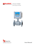
Industrial Process Controller
Model PC200
CTL-UM-00483-EN-04 (May 2014)
User Manual
Industrial Process Controller, Model PC200
Page ii
May 2014
User Manual
CONTENTS
Scope of This Manual . . . . . . . . . . . . . . . . . . . . . . . . . . . . . . . . . . . . . . . . . . . . . . . . . . . . . . . . . . . . . . . . . . . .5
Unpacking the PC200 . . . . . . . . . . . . . . . . . . . . . . . . . . . . . . . . . . . . . . . . . . . . . . . . . . . . . . . . . . . . . . . . . . . 5
Safety Considerations . . . . . . . . . . . . . . . . . . . . . . . . . . . . . . . . . . . . . . . . . . . . . . . . . . . . . . . . . . . . . . . . . . . 5
Safety Terminology and Symbols . . . . . . . . . . . . . . . . . . . . . . . . . . . . . . . . . . . . . . . . . . . . . . . . . . . . . . . . . 5
Safety Instructions . . . . . . . . . . . . . . . . . . . . . . . . . . . . . . . . . . . . . . . . . . . . . . . . . . . . . . . . . . . . . . . . . . 6
Disposal . . . . . . . . . . . . . . . . . . . . . . . . . . . . . . . . . . . . . . . . . . . . . . . . . . . . . . . . . . . . . . . . . . . . . . . . .6
Safety Rules and Precautionary Measures . . . . . . . . . . . . . . . . . . . . . . . . . . . . . . . . . . . . . . . . . . . . . . . . . . . .6
PC200 Batch Controller Description . . . . . . . . . . . . . . . . . . . . . . . . . . . . . . . . . . . . . . . . . . . . . . . . . . . . . . . . . . 7
Functions and Features . . . . . . . . . . . . . . . . . . . . . . . . . . . . . . . . . . . . . . . . . . . . . . . . . . . . . . . . . . . . . . . 7
Flow Meter Input . . . . . . . . . . . . . . . . . . . . . . . . . . . . . . . . . . . . . . . . . . . . . . . . . . . . . . . . . . . . . . . . . . . 7
Control Inputs . . . . . . . . . . . . . . . . . . . . . . . . . . . . . . . . . . . . . . . . . . . . . . . . . . . . . . . . . . . . . . . . . . . . . 7
Control Outputs . . . . . . . . . . . . . . . . . . . . . . . . . . . . . . . . . . . . . . . . . . . . . . . . . . . . . . . . . . . . . . . . . . . .7
Power Supply . . . . . . . . . . . . . . . . . . . . . . . . . . . . . . . . . . . . . . . . . . . . . . . . . . . . . . . . . . . . . . . . . . . . . .7
Configuration of the Unit . . . . . . . . . . . . . . . . . . . . . . . . . . . . . . . . . . . . . . . . . . . . . . . . . . . . . . . . . . . . . . 8
Display Information . . . . . . . . . . . . . . . . . . . . . . . . . . . . . . . . . . . . . . . . . . . . . . . . . . . . . . . . . . . . . . . . . .8
Installation . . . . . . . . . . . . . . . . . . . . . . . . . . . . . . . . . . . . . . . . . . . . . . . . . . . . . . . . . . . . . . . . . . . . . . . . . . 9
Installation Conditions . . . . . . . . . . . . . . . . . . . . . . . . . . . . . . . . . . . . . . . . . . . . . . . . . . . . . . . . . . . . . . . .9
Mounting the PC200 . . . . . . . . . . . . . . . . . . . . . . . . . . . . . . . . . . . . . . . . . . . . . . . . . . . . . . . . . . . . . . . . .9
Wiring the PC200 . . . . . . . . . . . . . . . . . . . . . . . . . . . . . . . . . . . . . . . . . . . . . . . . . . . . . . . . . . . . . . . . . . . . . 11
Voltage Selection Sensor Supply . . . . . . . . . . . . . . . . . . . . . . . . . . . . . . . . . . . . . . . . . . . . . . . . . . . . . . . . 11
Terminal Connectors . . . . . . . . . . . . . . . . . . . . . . . . . . . . . . . . . . . . . . . . . . . . . . . . . . . . . . . . . . . . . . . . 11
Operation . . . . . . . . . . . . . . . . . . . . . . . . . . . . . . . . . . . . . . . . . . . . . . . . . . . . . . . . . . . . . . . . . . . . . . . . . . 17
Control Panel . . . . . . . . . . . . . . . . . . . . . . . . . . . . . . . . . . . . . . . . . . . . . . . . . . . . . . . . . . . . . . . . . . . . . 17
Operator Information and Functions . . . . . . . . . . . . . . . . . . . . . . . . . . . . . . . . . . . . . . . . . . . . . . . . . . . . . . 18
Operator Alarms . . . . . . . . . . . . . . . . . . . . . . . . . . . . . . . . . . . . . . . . . . . . . . . . . . . . . . . . . . . . . . . . . . . 20
Configuration . . . . . . . . . . . . . . . . . . . . . . . . . . . . . . . . . . . . . . . . . . . . . . . . . . . . . . . . . . . . . . . . . . . . . . . 21
Programming the Setup Level . . . . . . . . . . . . . . . . . . . . . . . . . . . . . . . . . . . . . . . . . . . . . . . . . . . . . . . . . . 21
Transmitter Connections . . . . . . . . . . . . . . . . . . . . . . . . . . . . . . . . . . . . . . . . . . . . . . . . . . . . . . . . . . . . . 27
Transmitter Pulses Per Unit . . . . . . . . . . . . . . . . . . . . . . . . . . . . . . . . . . . . . . . . . . . . . . . . . . . . . . . . . . . . 28
Maintenance . . . . . . . . . . . . . . . . . . . . . . . . . . . . . . . . . . . . . . . . . . . . . . . . . . . . . . . . . . . . . . . . . . . . . . . . 29
Repair . . . . . . . . . . . . . . . . . . . . . . . . . . . . . . . . . . . . . . . . . . . . . . . . . . . . . . . . . . . . . . . . . . . . . . . . . 29
Technical Specifications . . . . . . . . . . . . . . . . . . . . . . . . . . . . . . . . . . . . . . . . . . . . . . . . . . . . . . . . . . . . . . . . . 30
General . . . . . . . . . . . . . . . . . . . . . . . . . . . . . . . . . . . . . . . . . . . . . . . . . . . . . . . . . . . . . . . . . . . . . . . . 30
Troubleshooting . . . . . . . . . . . . . . . . . . . . . . . . . . . . . . . . . . . . . . . . . . . . . . . . . . . . . . . . . . . . . . . . . . . . . . 32
Record of Configuration Settings . . . . . . . . . . . . . . . . . . . . . . . . . . . . . . . . . . . . . . . . . . . . . . . . . . . . . . . . . . . 33
May 2014
Page iii
Industrial Process Controller, Model PC200
Page iv
May 2014
User Manual
SCOPE OF THIS MANUAL
This manual is divided into two main sections:
• The daily use of the unit is described in “Operation” on page 17. These instructions are meant for users.
• The remaining chapters provide a detailed description of all software settings and hardware installation guidance. These
instructions and are meant exclusively for electricians/technicians.
This manual describes the standard unit as well as most of the options available. For additional information, please contact
your supplier.
IIMPORTAN
Read this manual carefully before attempting any installation or operation.
Keep the manual in an accessible location for future reference.
UNPACKING THE PC200
NNOTE: If damage to the shipping container is obvious, request that the carrier be present when the product is unpacked. All
claims for equipment damage during transit are the sole responsibility of the recipient.
After carefully unpacking the unit, check for any visible sign of damage. If found, notify the carrier for insurance purposes and
call the factory for possible replacement. Keep all packing material in the event that the unit must be returned to the factory.
NNOTE: Operating temperature is 32…130° F (0…55° C) with a maximum humidity of 85% non-condensing. Always select a
mounting location with proper ventilation and environmental protection.
SAFETY CONSIDERATIONS
Safety Terminology and Symbols
Indicates a hazardous situation, which, if not avoided, is estimated to be capable of causing death or serious personal injury.
Indicates a hazardous situation, which, if not avoided, could result in severe personal injury or death.
Indicates a hazardous situation, which, if not avoided, is estimated to be capable of causing minor or moderate personal
injury or damage to property.
May 2014
CTL-UM-00483-EN-03
Page 5
Industrial Process Controller, Model PC200
Safety Instructions
• LIFE SUPPORT APPLICATIONS: THE PC200 IS NOT DESIGNED FOR USE IN LIFE SUPPORT APPLIANCES, DEVICES, OR
SYSTEMS WHERE MALFUNCTION OF THE PRODUCT CAN REASONABLY BE EXPECTED TO RESULT IN A PERSONAL
INJURY. CUSTOMERS USING OR SELLING THESE PRODUCTS FOR USE IN SUCH APPLICATIONS DO SO AT THEIR OWN RISK
AND AGREE TO FULLY INDEMNIFY THE MANUFACTURER AND SUPPLIER FOR ANY DAMAGES RESULTING FROM SUCH
IMPROPER USE OR SALE.
• ELECTROSTATIC DISCHARGE INFLICTS IRREPARABLE DAMAGE TO ELECTRONICS! BEFORE INSTALLING OR OPENING THE
UNIT, INSTALLERS MUST DISCHARGE THEMSELVES BY TOUCHING A WELL-GROUNDED OBJECT.
• THIS UNIT MUST BE INSTALLED IN ACCORDANCE WITH THE EMC (ELECTROMAGNETIC COMPATIBILITY) GUIDELINES.
• CONNECT A PROPER GROUNDING TO THE ALUMINUM CASING AS INDICATED.
Disposal
Dispose of this product according to local regulations regarding waste electronic equipment. Dispose of the battery
separately. The separate collection and recycling of your waste equipment will help to conserve natural resources and ensure
that it is recycled in a manner that protects the environment.
Safety Rules and Precautionary Measures
The manufacturer accepts no responsibility whatsoever if the following safety rules and precaution instructions and the
procedures as described in this manual are not followed.
• Modifications of the PC200 implemented without preceding written consent from the manufacturer will result in the
immediate termination of product liability and warranty period.
• Installation, use, maintenance, and servicing of this equipment must be carried out by authorized technicians.
• Check the mains voltage and information on the manufacturer's plate before installing the unit.
• Check all connections, settings and technical specifications of the various peripheral devices with the PC200 supplied.
• Open the casing only if all leads are free of potential.
• Never touch the electronic components (ESD sensitivity).
• Never expose the system to heavier conditions than allowed according to the casing classification (see manufacturer's
plate and “Installation Conditions” on page 9).
• If the operator detects errors or dangers, or disagrees with the safety precautions taken, then inform the owner or
principal responsible.
• Adhere to the local labor and safety laws and regulations.
Page 6
CTL-UM-00483-EN-03
May 2014
User Manual
PC200 BATCH CONTROLLER DESCRIPTION
Functions and Features
The batch controller model PC200 is a microprocessor-driven instrument designed for batching and filling both small and
large quantities, as well as displaying total, accumulated total and flow rate.
This product is designed with a focus on:
• Ease-of-use with the numerical keyboard.
• Ruggedness for its application with a robust enclosure, keyboard and proper mechanical relays.
• Clear operator information: all relevant data can be monitored in one glance.
• User-friendly installation with quality plug-and-play terminals; suitable for both AC and DC applications (standard).
• A wide range of inputs, outputs and functions for a broad fulfillment in many applications.
Flow Meter Input
One flow meter: a passive or active pulse signal output can be connected to the PC200. The input circuit supports low and
high frequency flow meters. A power supply is available to power the sensor with 8 / 12 or 24V DC.
Control Inputs
The PC200 has six control inputs:
• Start
• Hold
• Resume
• Reset totalizer
• Reset cycle counter
• Lockout the entire keyboard
Control Outputs
The PC200 has five control outputs—two mechanical relay outputs and three transistor outputs. The two mechanical relay
outputs (make and break) are used for batching with two-stage control or one-stage control. Three transistor outputs are for
connection to PLCs or other controlling equipment. The function of relay R2 and the transistor outputs can be configured to:
• Batching
• Two-stage control
• High flow rate alarm
• Low flow rate alarm
• No‑flow alarm
• Any alarm
• Scaled pulse output
• Pre-warn or end of batch signal
Power Supply
AC power supply: as standard, the PC200 will operate on 110…230V AC.
DC power supply: as standard, the PC200 can also operate on 24V DC.
May 2014
CTL-UM-00483-EN-03
Page 7
Industrial Process Controller, Model PC200
Configuration of the Unit
The PC200 is designed for many types of applications. Use the SETUP level to configure your PC200 to your specific
requirements. For details, see “Configuration” on page 21 and “Record of Configuration Settings” on page 33.
The SETUP level includes several important features, such as K-factors, measurement units and selection of the control
outputs. All settings are stored in EEPROM memory and will not be lost in the event of power failure.
Display Information
The PC200 has a large transflective LCD with a bright LED backlight and displays symbols and digits for measuring units,
status information and keyword messages.
All total, accumulated total and batch counter information is stored in EEPROM memory and will not be lost in the event of
power failure.
Page 8
CTL-UM-00483-EN-03
May 2014
User Manual
INSTALLATION
• MOUNTING, ELECTRICAL INSTALLATION, STARTUP AND MAINTENANCE OF THIS INSTRUMENT MAY ONLY BE CARRIED
OUT BY TRAINED PERSONNEL AUTHORIZED BY THE OPERATOR OF THE FACILITY. PERSONNEL MUST READ AND
UNDERSTAND THIS OPERATING MANUAL BEFORE CARRYING OUT ITS INSTRUCTIONS.
• THE PC200 MAY ONLY BE OPERATED BY PERSONNEL WHO ARE AUTHORIZED AND TRAINED BY THE OPERATOR OF THE
FACILITY. OBSERVE ALL INSTRUCTIONS IN THIS MANUAL.
• ENSURE THAT THE MEASURING SYSTEM IS CORRECTLY WIRED ACCORDING TO THE WIRING DIAGRAMS. PROTECTION
AGAINST ACCIDENTAL CONTACT IS NO LONGER ASSURED WHEN THE HOUSING COVER IS REMOVED OR THE PANEL
CABINET HAS BEEN OPENED (DANGER FROM ELECTRICAL SHOCK). THE HOUSING MAY ONLY BE OPENED BY
TRAINED PERSONNEL.
• OBEY ALL SAFETY PRECAUTIONS MENTIONED IN “Safety Considerations” on page 5.
Installation Conditions
Figure 1: Acceptable installation conditions
Consider the IP classification of the casing (see the manufacturer's plate) when selecting a location for the PC200. An IP65
(NEMA 4X) casing should NEVER be exposed to weather conditions.
When used in very cold surroundings or varying climatic conditions, take the necessary precautions against moisture by
placing a dry sachet of silica gel, or similar material, inside the instrument case.
Mounting the PC200
Mount the PC200 on a solid structure to avoid vibrations. The basic unit is equipped for panel mount. To install:
1. Measure and cut the mounting hole to the dimensions shown in Figure 2 on page 10.
2. Install the gasket around the mounting bezel.
3. Insert the unit through the front panel cutout.
4. Secure the unit to the panel with the mounting clips.
May 2014
CTL-UM-00483-EN-03
Page 9
Industrial Process Controller, Model PC200
Figure 2: Enclosure dimensions
Figure 3: Grounding enclosure
IIMPORTAN
Installations must have a reliable ground connection for the sensor and the metal casing.
Installations must have an effective screened cable for the input signal and grounding of its screen to the ground terminal or at the
sensor itself, whichever is appropriate to the application.
Page 10
CTL-UM-00483-EN-03
May 2014
User Manual
WIRING THE PC200
At installation, be sure to comply with the following requirements:
• Disconnect power to the unit before attempting any connection or service to the unit.
• Avoid using machine power service for AC power. When possible, use a dedicated or lighting circuit.
• Do not bundle or route signal lines with power lines.
• Keep all lines as short as possible.
• Use shielded wire for all input wiring.
• Observe all local electrical codes.
TO PREVENT ACCIDENTS, POWER SHOULD NOT BE APPLIED UNTIL ALL OTHER CONNECTIONS HAVE BEEN COMPLETED.
Voltage Selection Sensor Supply
Sensor supply
8.2…12 or 24V DC
A power supply for the sensor is available. The flow meter can be powered with 8.2, 12 or 24V DC.
Total power consumption
Max. 50 mA @ 24V
The voltage is selected with the two switches at the rear of the enclosure.
Switch positions
Voltage Selection
Figure 4: Switch setting sensor supply voltage
Switch 1
Switch 2
Voltage
on
on
24V DC
on
off
8.2V DC
off
off
12V DC
Table 1: Switch positions
Terminal Connectors
Figure 5: Overview of terminal connectors
May 2014
CTL-UM-00483-EN-03
Page 11
Industrial Process Controller, Model PC200
Terminal #01-02; lock keyboard:
Use the LOCK KEYBOARD function to connect a lock or jumper in order to disable the complete keyboard while the functions
from the terminals remain available. Certain keys on the keyboard can be locked-out with SETUP 85 or passcode-protected
with SETUP 84. Terminal #11 can block the batch process.
Terminal #03-07; flow meter input:
• A high or low frequency NPN signal can be connected to the PC200. For low frequency sensors like a reed switch, a low
pass filter on terminal #07 eliminates contact bounce. For higher frequencies, use terminal #06.
• Use terminal #05 for a 12V DC sensor supply. Use terminal #29 for 8.1, 12 or 24V DC.
• The screen of the signal wire must be connected to the common ground terminal #03 (unless earthed at the sensor itself ).
Terminal #04 is not used.
• Active signals switching between 0…8V DC, 0…12V DC or 0…24V DC can be connected as well.
Reed - switch signal input
INTERNAL
EXTERNAL
+ 3.2V DC
1M
7
low-pass filter
selection REED-LP
Common ground unit
3
SIGNAL
shielding
REED
SWITCH
shielding
NPN
GND
Figure 6: Reed switch signal input
NPN signal input - above 150Hz
INTERNAL
EXTERNAL
+ 3.2V DC
100K
6
Common ground unit
3
SIGNAL
GND
Figure 7: NPN signal input
Active signal input
INTERNAL
EXTERNAL
5 or 29
6
SIGNAL
3
GND
(8.1V, 12V, 24V)
shielding
Common ground unit
Figure 8: Active signal input
Page 12
CTL-UM-00483-EN-03
May 2014
User Manual
Terminal #08-09; External control start:
Use the EXTERNAL CONTROL START function to remotely start the batch controller. The input must be switched with a
potential-free contact to the GND terminal number #08 for at least 100 msec.
External START input
INTERNAL
EXTERNAL
+ 3.2V DC
1M
9
low-pass filter
SIGNAL
shielding
Common ground unit
8
START
SWITCH
GND
Figure 9: External start input
Terminal #08-10; External control hold:
Use the EXTERNAL CONTROL HOLD function to interrupt the batch process and bring it to HOLD status. The input must be
switched with a potential-free contact to the GND terminal #08 for at least 100 msec.
External HOLD input
INTERNAL
EXTERNAL
+ 3.2V DC
1M
low-pass filter
10
SIGNAL
shielding
Common ground unit
8
HOLD
SWITCH
GND
Figure 10: External hold input
Terminal #08-11; External control reset batch:
Use the EXTERNAL CONTROL RESET BATCH function to remotely clear the batch process in HOLD status. The input must be
switched with a potential-free contact to the GND terminal #08 for at least 100 msec.
You can also use terminal #11 to block the batch process: as long as this input is switched to terminal 8, it is not possible to
start a batch (the START button on the keyboard is blocked as well).
May 2014
CTL-UM-00483-EN-03
Page 13
Industrial Process Controller, Model PC200
External RESET BATCH input
INTERNAL
EXTERNAL
+ 3.2V DC
1M
11
low-pass filter
SIGNAL
shielding
Common ground unit
8
RESUME
SWITCH
GND
Figure 11: External reset batch input
Terminal #08-12; Reset totalizer:
Use the RESET TOTALIZER function for end-of-shift coordination and control. You can reset the inventory totalizer to zero. The
input must be switched with a potential-free contact to the GND terminal #08 for at least 100 msec.
You can also use terminal #12 to block the RESET function from the keyboard: as long as this input is switched to terminal #08,
it is not possible to clear the actual totalizer. You must release the input to clear the total.
External RESET TOTALIZER input
INTERNAL
EXTERNAL
+ 3.2V DC
1M
low-pass filter
12
SIGNAL
shielding
Common ground unit
8
RESET
TOTALIZER
SWITCH
GND
Figure 12: External reset totalizer input
Terminal #13-16; Transistor outputs T1, T2 and T3:
The function of these TRANSISTOR OUTPUTS is determined by SETUP functions 72-79.
The maximum driving capacity is 300 mA @ 50V DC per transistor.
Page 14
CTL-UM-00483-EN-03
May 2014
User Manual
Passive transistor outputs - T1, T2 and T3
INTERNAL
EXTERNAL
16
DEVICE
T3
15
DEVICE
T2
14
DEVICE
T1
+
+
+
Maximum
50V DC - 300mA
Common ground unit
13 - GND
Figure 13: Passive transistor outputs T1, T2 and T3
Terminal #22-24; 80…230V AC power supply:
Connect AC power only after all other wiring has been completed.
The PC200 has an internally mounted line filter and fuse for surge protection. The unit is designed to operate with
85…265V AC power or DC voltages (see terminal #27-28).
Always make sure to connect terminal #24 to the electrical system ground.
Terminal #27-28; 24V DC power supply:
Use these terminals ONLY for DC-operated applications. The supply must be a 24V DC +10%.
For AC applications, use terminals 22-24.
Terminal #30; Reset cycle counter:
Use the RESET CYCLE COUNTER function for end-of-shift coordination and control. The inventory cycle counter can be reset to
zero. The input must be switched with a potential-free contact to the GND terminal #01 or #08 for at least 100 msec.
You can also use terminal #30 to block the RESET function from the keyboard: as long as this input is switched to terminal #1
or #08, it is not possible to clear the actual counter. You must first release the input to clear the COUNT value.
External RESET CYCLE COUNTER input
INTERNAL
EXTERNAL
+ 3.2V DC
1M
low-pass filter
30
SIGNAL
shielding
Common ground unit
1 or 8
RESET
CYCLE
COUNTER
SWITCH
GND
Figure 14: External reset cycle counter input
Terminal #42-44; control output R1:
Use the mechanical relay CONTROL OUTPUT R1 to control the batch process. Relay 1 is switched ON during the whole batch
process. The maximum switch power is 240V-3A per output.
May 2014
CTL-UM-00483-EN-03
Page 15
Industrial Process Controller, Model PC200
Mechanic relay output - R1
INTERNAL
EXTERNAL
42 - NO
43- C
maximum
240V AC - 3A
44 - NC
Figure 15: Mechanical relay output R1
Terminal #46-48; control output R2:
The function of the mechanical relay 2 is determined by SETUP function 71.
The maximum switch power is 240V-3A per output.
Mechanic relay output - R2
INTERNAL
EXTERNAL
46 - NO
47- C
maximum
240V AC - 3A
48 - NC
Figure 16: Mechanical relay output R2
Page 16
CTL-UM-00483-EN-03
May 2014
User Manual
OPERATION
THE PC200 MAY BE OPERATED ONLY BY PERSONNEL WHO ARE AUTHORIZED AND TRAINED BY THE OPERATOR OF THE
FACILITY. OBSERVE ALL INSTRUCTIONS IN THIS MANUAL. OBEY ALL SAFETY PRECAUTIONS MENTIONED IN “SAFETY
CONSIDERATIONS” ON PAGE 5.
Control Panel
Figure 17: PC200 control panel
Function Keys
Press PROG then use keys 0 to 9 and
to enter a PRESET value or configuration value.
Press RATE to display the actual flow rate during batching.
Press TOTAL once to display and reset the actual total.
Press TOTAL twice to display the accumulated total.
Press COUNT to display and reset the number of executed batches.
0
Press PRINT to print the currently displayed information.
PRINT
Press START to begin the batch process or to resume after a HOLD situation.
Press HOLD to interrupt the batch process.
Press RESET after pressing HOLD to completely cancel a batch process.
At the SETUP level, press RESET to reset the totalizers and other values.
Press PROG/ENTER to enter the programming function, to save new PRESET values or other settings and to gain
access to the SETUP level. See “Configuration” on page 21.
Press after pressing PROG to enter a decimal value. During configuration, press
See “Configuration” on page 21.
to select a function or value.
During configuration, press this arrow key to select a function or value. See “Configuration” on page 21.
May 2014
CTL-UM-00483-EN-03
Page 17
Industrial Process Controller, Model PC200
Operator Information and Functions
In general, the PC200 functions at the Operator level. The information displayed and the functional keys available depend on
the SETUP settings and the active function.
A key symbol
indicates a particular key or function is locked and not available.
Enter a Batch Quantity
To change the PRESET value:
1. Press PROG. The word "PROGRAM" flashes on the display.
2. Use the numerical keyboard 0-9 and the decimal position to enter the new value.
3. Press ENTER to save the new value or press RESET to cancel the change and keep the PRESET value.
Figure 18: Example display information during programming preset value
Batch Maximum / Minimum
If you try to program a value that is not valid (the batch size is too large or too small), the increase ( ) or decrease ( ) sign
displays. The new value is ignored and the minimum or maximum allowed value is set.
Starting the Batch Process
The batch process can only be started up when "READY" is displayed. The batch process is started up by pressing the START
key. Depending on the SETUP settings, one or two relays will be switched. The arrows at the display indicate if the ACTUAL
value will be counting up or down.
Once the PRESET quantity is reached, the batch outputs will be switched off and the batch process is ended. A next batch can
be started with the same PRESET quantity or a new value can be entered.
The PC200 is equipped with a smart (self learning) overrun correction: at the end of the process, the outputs will be switched
OFF earlier as the PRESET value, taking the overrun quantity of previous batches into account. The result is an accurate batch,
even in slowly varying circumstances. During overrun, a clock will display and "R1 / R2" will be flashing.
Figure 19: Example display information during the process
Page 18
CTL-UM-00483-EN-03
May 2014
User Manual
Interrupting and Ending the Batch Process
When you press HOLD, the batch process is temporarily interrupted; the actual values are not lost. The word "HOLD" flashes
on the display. From this point, you can press START to resume the batch process.
You can end the batch process entirely at any time by pressing RESET.
NNOTE: The actual values are lost and the system returns to steady state. The batch cannot be resumed.
Figure 20: Example display information when interrupted
Additional key functions:
Flow rate indication
During batching, the actual flow rate will display after pressing the RATE key. To
return to the main display: press RATE again or wait for 20 seconds.
Display total and accumulated total When the TOTAL key is pressed once, the resettable total will display. After
pressing this key again, accumulated total will display.
The accumulated total cannot be reinitialized. The value will count up to
9,999,999,999. The unit and number of decimals are displayed according to the
configuration settings for preset. To return to the main display: press TOTAL
again or wait for 20 seconds.
Clear total
The value for total can be reinitialized. To do so, select TOTAL and press RESET:
the flashing text "PUSH RESET" will display.
To avoid reinitialization at this stage, press a key other than RESET or wait for 20
seconds. If RESET is pressed again, TOTAL will be reset to zero.
Reinitialization of total DOES NOT influence the accumulated total.
NNOTE: Total can only be reset if no batch process is active (status: READY).
Display batch counter
Clear batch counter
May 2014
NNOTE: This function might not be available due to configuration settings.
The number of completed batches is displayed after pressing COUNT. To return
to the main display: press COUNT again or wait for 20 seconds.
The value batch counter can be reinitialized. To do so, select COUNT and press
RESET: the flashing text "PUSH RESET" will display.
To avoid reinitialization at this stage, press a key other than RESET or wait for
20 seconds. If RESET is pressed again, COUNT will be reset to zero.
NNOTE: COUNT can only be reset if no batch process is active (status: READY).
NNOTE: This function might not be available due to configuration settings.
CTL-UM-00483-EN-03
Page 19
Industrial Process Controller, Model PC200
Operator Alarms
No Flow Alarm
The PC200 offers a no-flow monitoring feature: if the flow meter fails to generate a signal during a certain period of time, the
unit will shut off the control outputs and bring the batch controller in HOLD and alarm mode. A “NO FLOW” alarm message
will display.
To clear the alarm, press RESET once while the batch controller remains in HOLD mode. When in HOLD mode, the batch can
be continued or interrupted. See “Interrupting and Ending the Batch Process” on page 19.
Flow Rate Alarm
If during a batch process the actual flow rate is outside the allowed range, a “LO RATE”, or “HI RATE” alarm message will display,
indicating the type of alarm: “LO RATE”, “HI RATE”.
Based on the configuration setting 4.5 Reset Flow Rate Alarm, the following will happen:
• Auto mode: The process is not interrupted, the alarm cannot be cleared and will disappear once the flow rate is within its
limits again.
• Manual mode: Press FLOW RATE followed by RESET to acknowledge the alarm; the alarm will disappear. The alarm will be
cleared automatically in case the batch process is ended.
• Hold mode: The batch process will go on HOLD automatically as soon as the flow rate is outside the allowed range. To clear
the alarm, press RESET once, while the batch controller remains in HOLD mode. When in HOLD mode, the batch can be
continued or cancelled completely. See “Interrupting and Ending the Batch Process” on page 19.
Alarm 01-03
If “ALARM” is displayed when no process alarm is present (no flow or flow rate alarm), press the “1” key to display the reason for
the alarm.
See “Troubleshooting” on page 32.
Page 20
CTL-UM-00483-EN-03
May 2014
User Manual
CONFIGURATION
This section, which describes software settings and hardware connections, is exclusively meant for electricians and
non-operators.
• MOUNTING, ELECTRICAL INSTALLATION, STARTUP AND MAINTENANCE OF THE INSTRUMENT MAY ONLY BE
PROVIDED BY TRAINED PERSONNEL AUTHORIZED BY THE OPERATOR OF THE FACILITY. PERSONNEL MUST READ AND
UNDERSTAND THIS MANUAL BEFORE CARRYING OUT ITS INSTRUCTIONS.
• ENSURE THAT THE MEASURING SYSTEM IS CORRECTLY WIRED ACCORDING TO THE WIRING DIAGRAMS. THE HOUSING
MAY ONLY BE OPENED BY TRAINED PERSONNEL.
• OBEY ALL SAFETY PRECAUTIONS MENTIONED IN “Safety Considerations” on page 5.
Programming the Setup Level
Figure 21: Matrix structure setup level
Configuration of the PC200 is done at the SETUP level.
To access the SETUP level, press PROG/ENTER for 7 seconds.
Both arrows will display.
To return to the operator level, press and hold PROG for three seconds. If
no key is pressed for 2 minutes, the unit will automatically exit SETUP.
NNOTE: SETUP can only be reached if the PC200 is in “READY” mode.
During SETUP, the batch controller cannot be used for batching!
NNOTE: A passcode may be required to enter SETUP. Without this
passcode, access to SETUP is denied.
Scrolling Through the Setup Level
Selection of function-group and function:
SETUP is divided into several function groups and functions. Each function has a unique number. The number is a
combination of two figures. The first figure indicates the function-group and the second figure the sub-function. Additionally,
each function is expressed with a keyword.
The functions can be selected with these arrow keys. After selecting a sub-function, the next main function is
selected by scrolling through all sub-functions (for example, 1 , 11 , 12 , 13 , 14 ,
1 , 2 , 3 , 31 ).
To change or select a value:
After PROG has been pressed:
• To change a value, use the numerical keyboard.
• To select a setting, use and .
If you try to program a value that is not valid (the batch size is too large or too small), the increase ( ) or decrease ( ) sign
displays. The new value is ignored and the minimum or maximum allowed value is set.
When data is altered but ENTER is not pressed, the alteration can be cancelled by waiting for 20 seconds or by pressing ENTER
for three seconds: the PROG-procedure will be left automatically and the former value reinstated.
NNOTE: Alterations will only be set after you press ENTER.
To return to OPERATOR-level:
To return to the operator level, press PROG for 3 seconds. If no key is pressed for 2 minutes, SETUP will be automatically left.
May 2014
CTL-UM-00483-EN-03
Page 21
Industrial Process Controller, Model PC200
Overview of the Setup Functions
SETUP FUNCTIONS AND VARIABLES
1. PRESET
11 UNIT
12 DECIMALS
13 BATCH MINIMUM
14 BATCH MAXIMUM
L, m , USGAL, IGAL, ft , bbl
0, 1, 2, 3 (Ref: displayed value)
X,XXX,XXX quantity
X,XXX,XXX quantity
Default
USGAL
0
0 USGAL
0 USGAL
15
X,XXX,XXX quantity
0 USGAL
PRESET VALUE
2. OVERRUN
21 OVERRUN
22 TIME
3. Flow rate
31 UNIT
32 TIME UNIT
33 DECIMALS
34 CALCULATION
35 Cutoff
4. ALARM
41 NO-FLOW alarm
42 LOW flow rate alarm
43 HIGH flow rate alarm
44 DELAY flow rate alarm
45 RESET flow rate alarm
5. DISPLAY
51 DISPLAY
52 BACKLIGHT brightness
53
DIM BACKLIGHT
6. FLOW METER
61 UNIT K-FACTOR
62 K-FACTOR
7. CONTROL
71 RELAY 2
72 TRANSISTOR 1
73 TRANSISTOR 2
74 TRANSISTOR 3
75 PRECLOSE volume
76 PREWARN time
77 PULSE WIDTH
78 PULSE PER
79 PULSE ACCORDING
8. OTHERS
81 MODEL
82 SOFTWARE VERSION
83 SERIAL NO.
84 PASSWORD
85 Keyboard lock
86 TAGNUMBER
3
3
disable, enable
0.1…999.9 seconds
L, m3, USGAL, IGAL, ft3, bbl
sec, min, hour, day
0, 1, 2, 3 (Ref: displayed value)
per 1…255 pulses
0.1…999.9 seconds
0.0…999.9 seconds
0000.000…9,999,999
0000.000…9,999,999
0.0…999.9 seconds
automatic, manual, stop batch
Increase, decrease
Off, 20%, 40%, 60%, 80%, 100%
Off, 20%, 40%, 60%, 80%, 100%
L, m3, USGAL, IGAL, ft3, bbl
0.000010…9,999,999
batch, preclose, HI flow, LO flow, no-flow, any flow, pulse, pre-warn, end of batch
batch, preclose, HI flow, LO flow, no-flow, any flow, pulse, pre-warn, end of batch
batch, preclose, HI flow, LO flow, no-flow, any flow, pulse, pre-warn, end of batch
batch, preclose, HI flow, LO flow, no-flow, any flow, pulse, pre-warn, end of batch
X,XXX,XXX quantity
0.1, 999.9 sec
0.001, 9.999 sec
X,XXX,XXX quantity
Acc. Total, batch
PC200
02.____.____
--.--.--0000, 9999
Start, hold, preset, control, all, off
0000000, 9999999
Default
disable
1.0 sec
Default
USGAL
minute
0
10
30.0 sec
Default
0.0 sec
0 USGAL
0 USGAL
0.0 sec
auto
Default
increase
100%
100%
Default
USGAL
1
Default
Batch
Batch
Pulse
Any flow
0 USGAL
0.0 sec
0.000 sec
1000 USGAL
Acc.Total
Default
PC200
—
—
0000
off
0
Table 2: Setup functions overview
Page 22
CTL-UM-00483-EN-03
May 2014
User Manual
Details of the Setup Functions
UNIT
11
1 – PRESET
SETUP – 11 determines the measurement unit for preset, total, accumulated total and
pulse output.
The following units can be selected:
L, m3, USGAL, IGAL, ft3, bbl
DECIMALS
12
BATCH MINIMUM
13
BATCH MAXIMUM
14
PRESET VALUE
15
Alteration of the measurement unit will have consequences for operator and SETUP level values.
The decimal point determines the number of digits following the decimal point for preset, total,
accumulated total and pulse output.
The following can be selected:
0000000, 111111.1, 22222.22, 3333.333
This function prevents the operator from entering a new PRESET value that is less than the
entered batch minimum.
Value zero (0) disables this function.
This function prevents the operator to enter a new PRESET value which is more than the entered
batch maximum.
Value zero (0) disables this function.
A Preset value usually will be entered by the Operator at Operator level. However, that function
can be locked out by SETUP 84 or from the terminal input. With this function, a Preset value can be
entered conveniently at configuration level (which can be password-protected).
Table 3: Preset functions
2 – OVERRUN
Overrun can occur at the end of the batch process, as a result of slowness of a valve or pump. Consequently, the accuracy is
less. With this function, the PC200 analyzes the actual overrun characteristic of every batch again. This information is used to
correct the overrun automatically.
OVERRUN
For an accurate overrun correction, the flow meter must:
21
• Be high resolution.
• Show no false overrun due to a slow update time.
TIME (OVERRUN)
22
• Not spin once the valve is closed.
Do not enable this function if the flow meter does not meet these technical demands.
The overrun characteristic of the system will be analyzed during a certain time after switching-off
the valves. This eliminates false signals generated through leakage.
Enter the time you expect the system needs to stop a batch. Provide some extra time to avoid an
incorrect overrun correction.
NNOTE: The next batch can only be started after the overrun time elapses.
The minimum overrun time is 0.1 second.
The maximum overrun time is 999.9 seconds.
Table 4: Overrun functions
May 2014
CTL-UM-00483-EN-03
Page 23
Industrial Process Controller, Model PC200
MEASUREMENT UNIT
31
3 – FLOW RATE
SETUP – 21 determines the measurement unit for flow rate.
The following units can be selected:
L, m3, USGAL, IGAL, ft3, bbl
TIME UNIT
32
DECIMALS
33
CALCULATION
34
Cutoff TIME
35
Alteration of the measurement unit will have consequences for other SETUP level values (high and
low flow rate alarms).
The flow rate can be calculated per second (SEC), minute (MIN), hour (HR) or day (DAY).
Alteration of the time unit will have consequences for other SETUP level values (high and low flow
rate alarms).
This setting determines for flow rate the number of digits following the decimal point. The
following can be selected:
00000, 1111.1, 2222.22, 3333.333
Alteration of the decimals will have consequences for other SETUP level values (high and low flow
rate alarms).
The flow rate is calculated by measuring the time between a number of pulses, for example 10
pulses. The more pulses the more accurate the flow rate will be. The maximum value is 255 pulses.
NNOTE: For low frequency applications (below 10 Hz): do not program more than 10 pulses or the
update time will be very slow.
NNOTE: For high frequency application (above 1 kHz) program a value of 50 or more pulses.
With this setting, you determine a minimum flow requirement threshold, if during this time less
than XXX-pulses (SETUP 34) are generated, the flow rate will display as zero.
Enter the cutoff time in seconds. The maximum time is 999.9 seconds (about 15 minutes).
Table 5: Flow rate functions
4 – ALARM
NO-FLOW ALARM
The PC200 offers a no-flow monitoring feature: if the flow meter fails to generate a signal during
41
a certain period of time, the unit will shut off the control outputs and bring the batch controller in
HOLD and alarm status. After clearing the alarm, the batch can be continued or denied.
The maximum time to generate a signal is 999.9 seconds (about 15 minutes).
With value zero (0) this function is disabled.
LOW-Flow rate ALARM The minimum required flow rate is set with this setting. Once the flow rate is lower as this value
(MINIMUM)
and the delay time has passed (setting 44), a low flow rate alarm will be generated.
42
With value zero (0) this function is disabled.
HIGH-Flow rate ALARM The maximum allowed flow rate is set with this setting. Once the flow rate is above this value and
(MAXIMUM)
the delay time has passed (setting 44), a high flow rate alarm will be generated.
43
With value zero (0) this function is disabled.
DELAY TIME FLOW
An alarm generated by SETUP 42 or 43 can be ignored during X-time.
RATE ALARM
If the actual flow rate is still incorrect after this delay time an alarm will be generated.
44
RESET Flow rate
Once a flow rate alarm has been generated, select a way to proceed:
ALARM
• Automatic: the batch process will not get on hold, the alarm situation will display on the LCD
45
and if applicable, on the control outputs. If the flow rate comes within the allowed range, the
alarm will be reset automatically.
• Manual: as automatic, but the alarm has to be RESET by the operator.
• Stop batch: as automatic but the process will be on HOLD: the Operator can resume or reset
the batch.
Table 6: Alarm functions
Page 24
CTL-UM-00483-EN-03
May 2014
User Manual
DISPLAY
52
BRIGHTNESS
52
5 – DISPLAY
The actual batched value can be set to display the batched quantity (increase), or to display the
remaining quantity to be batched (decrease).
The density of the backlight can be set in steps of 20% in the range:
0…100%
Table 7: Display
6 – FLOW METER
The PC200 is able to handle high and low frequency pulses. Do use the right terminal connection. See “Installation” on
page 9.
The PC200 calculates automatically the internal K-Factors for selected measuring units for PRESET (SETUP 11) and Flow rate
(SETUP 31).
UNIT K-FACTOR
SETUP – 61 determines the measurement unit for the K-Factor entry (setting 62). According to the
61
calibration sheet of your flow meter, a certain number of pulses are generated versus a certain
volume and measuring unit. Enter the measuring unit.
The following units can be selected: L, m3, USGAL, IGAL, ft3, bbl
Alteration of the measurement unit will have consequences for operator and SETUP level values.
K-FACTOR
With the K-factor, the flow meter pulse signals are converted to a quantity. The K-factor is based
62
on the number of pulses generated by the flow meter per selected measurement unit (SETUP 61),
for example per cubic feet. The more accurate the K-factor, the more accurate the functioning of
the system will be.
Example 1: Calculating the K-factor.
Let us assume that the flow meter generates 248.13 pulses per liter. So, the K-factor is 248.13.
Enter for SETUP – 61: “Liter”.
Enter for SETUP – 62: “248.13”.
Example 2: Calculating the K-factor.
Let us assume that the flow meter generates 6.5231 pulses per gallon. So, the K-Factor is 6.5231.
Enter for SETUP – 61: “USGAL”.
Enter for SETUP – 62: “6.5231”.
Table 8: Flow meter functions
May 2014
CTL-UM-00483-EN-03
Page 25
Industrial Process Controller, Model PC200
7 – RELAY OUTPUT
Two mechanical control outputs are available to control relays or valves. Relay 1 is always used as the main batch control
relay, its function cannot be determined.
The second relay as well as the three transistor outputs can be used for the desired function:
• Batch: the function is equal to relay 1.
• Preclose: used for two-stage control. See SETUP 75.
• LO flow alarm: switched once a low flow rate alarm has been triggered. See SETUP 42.
• HI flow alarm: switched once a high flow rate alarm has been triggered. See SETUP 43.
• No-flow alarm: switched in case a no-flow is triggered. See SETUP 41.
• Any flow alarm: switched in case a flow rate or no-flow alarm will be triggered.
• Pre-warn: to generate a switch signal at X-volume before end-of batch. See SETUP 75 and 76.
• Pulse: for use as a scaled pulse output. See SETUP 77 and 78.
• End of batch: will switch on at the end of a batch till a next batch is started (so reverse to the batch process).
RELAY 2
Function according to:
71
batch / preclose / HI flow rate alarm / LO flow rate alarm / no-flow alarm / any flow alarm / pulse /
pre-warn / end of batch
TRANSISTOR 1
Function according to:
72
batch / preclose / HI flow rate alarm / LO flow rate alarm / no-flow alarm / any flow alarm / pulse /
pre-warn / end of batch
TRANSISTOR 2
Function according to:
73
batch / preclose / HI flow rate alarm / LO flow rate alarm / no-flow alarm / any flow alarm / pulse /
pre-warn / end of batch
TRANSISTOR 3
Function according to:
74
batch / preclose / HI flow rate alarm / LO flow rate alarm / no-flow alarm / any flow alarm / pulse /
pre-warn / end of batch
PRECLOSE QUANTITY According to the setting Preclose, the switch moment of the output is based on the remaining
75
quantity before the end of batch.
With value zero (0) this function is disabled.
PREWARNING
According to the setting Pre-warn, the output will be switch at the moment of Preclose during
76
X- seconds.
This time can be set in the range: 0.1…999.9 seconds.
PULSE WIDTH
The pulse width determines the time that the output will be switched; in other words the pulse
77
length. This pulse length determines also the maximum frequency based on a 50/50 duty cycle.
Maximum frequency = 1 / 2*pulse length (in seconds)
The pulse width is set in milliseconds in the range 0.001…9.999 seconds.
Value “zero” disable the pulse output.
NNOTE: If the frequency should go out of range—when the flow rate increases, for example—an
internal buffer will be used to store the missed pulses: As soon as the flow rate slows
down, the buffer will be emptied. It might be that pulses will be missed due to a bufferoverflow, so it is advised to program this setting within its range!
IMPULSE PER
A pulse will be generated every X-quantity.
78
Enter this quantity while taking the displayed decimal position and measuring unit into account
(according to PRESET).
PULSE ACCORDING
This function determines if a pulse will be generated according the quantity batched or according
ACC. TOTAL / BATCH
to accumulated total.
79
With setting BATCH, the pulse generator will be set to zero when a new batch is started up (and
does not reflect the complete totalized volume).
Table 9: Relay output
Page 26
CTL-UM-00483-EN-03
May 2014
User Manual
MODEL
81
VERSION FIRMWARE
82
SERIAL NUMBER
83
KEYBOARD LOCK
85
8 – OTHERS
For support and maintenance: provide this information to your supplier.
For support and maintenance: provide this information to your supplier.
For support and maintenance: provide this information to your supplier.
The LOCK function inhibits certain functions of the keyboard:
• Start: to lock the START key; a batch cannot be executed.
• Hold: to lock the HOLD key; a batch cannot be interrupted.
• Preset: to lock the ability to change the batch value.
• Control: START and HOLD are both locked out.
• All: the complete keyboard is locked, except SETUP functionality.
• Off: this lock function is disabled.
NNOTE: The Lock function on terminal 2 will lock the complete keyboard and can be used in
combination with this Inhibit function.
NNOTE: The functions available from the cable terminals remain in use!
For identification of the unit and communication purposes, a unique tag number of maximum
seven digits can be entered.
TAGNUMBER
86
Table 10: Other functions
Transmitter Connections
Device
PM5
MS-ESXP
MS-EA
MS-ER1
Wire Color
RED
BLACK
GREEN
PC200 Connection
7
3
GROUND
Device
PFT3
FT1
FT-2XP
PFT-2
Meter Mounted PC200
Wire Color
WHITE
WHITE
PC200 Connection
7
3
Device
FT-1E
PFT-2E
PFT-3E
Wire Color
RED
BLACK
GREEN
PC200 Connection
5, 29
3, 27
6
Wire Color
RED
BLACK
GREEN
PC200 Connection
6
3, 27
GROUND
NNOTE: See “Voltage Selection Sensor Supply” on page 11.
Device
EPT-1XP
PEPT-1
Table 11: Transmitter connections
May 2014
CTL-UM-00483-EN-03
Page 27
Industrial Process Controller, Model PC200
Transmitter Pulses Per Unit
Use with the following transmitters: FT1, FT2XP, PFT2, PFT3, RST, RST-6P
Size
Meter Model
US Gallons
Liters
Ft3
1/2"
OP
222.960
58.899
1687.857
1/2"
OP (FT1 only)
111.500
29.455
834.078
1"
OP
76.640
20.246
573.307
2"
OP
20.600
5.442
154.099
2"
Industrial Turbo
17.360
4.586
129.862
3"
Industrial Turbo
12.400
3.276
92.758
4"
Industrial Turbo
2.560
0.676
19.150
6"
Industrial Turbo
1.080
0.285
8.079
5/8"
LP RCDL
229.554
60.641
1717.186
5/8"
25 RCDL
198.340
52.396
1484.689
3/4"
35 RCDL
126.671
33.463
947.566
1"
40 RCDL
89.781
23.717
671.610
1"
55 RCDL
58.064
15.339
434.351
1"
70 RCDL
46.752
12.350
349.726
1-1/2"
120 RCDL
23.867
6.305
178.539
2"
170 RCDL
14.565
3.848
108.955
1-1/2"
160 Turbo Series
1.537
0.406
11.495
2"
200 Turbo Series
1.537
0.406
11.495
3"
450 Turbo Series
1.598
0.422
11.955
4"
1000 Turbo Series
1.665
0.440
12.455
6"
2000 Turbo Series
0.150
0.040
1.122
8"
3500 Turbo Series
0.151
0.040
1.133
10"
5500 Turbo Series
0.198
0.052
1.481
12"
6200 Turbo Series
0.129
0.034
0.963
16"
6600 Turbo Series
0.016
0.004
0.116
20"
10000 Turbo Series
0.009
0.002
0.067
1/2"
Industrial OG
378.5 *
100 *
2831 *
3/4"
Industrial OG
249.8 *
66 *
1868 *
1"
Industrial OG
249.8 *
66 *
1868 *
1" HF
Industrial OG
162.8 *
43 *
1217 *
1-1/2"
Industrial OG
64.4 *
17 *
481 *
2"
Industrial OG
34.1 *
9*
255 *
3"
Industrial OG
11.4 *
3*
85 *
Table 12: Transmitter pulses per unit
* Approximate values. Exact pulses/liter for water is listed on each meter.
Page 28
CTL-UM-00483-EN-03
May 2014
User Manual
MAINTENANCE
• MOUNTING, ELECTRICAL INSTALLATION, STARTUP AND MAINTENANCE OF THIS INSTRUMENT MAY ONLY BE CARRIED
OUT BY TRAINED PERSONNEL AUTHORIZED BY THE OPERATOR OF THE FACILITY. PERSONNEL MUST READ AND
UNDERSTAND THIS OPERATING MANUAL BEFORE CARRYING OUT ITS INSTRUCTIONS.
• THE PC200 MAY ONLY BE OPERATED BY PERSONNEL WHO ARE AUTHORIZED AND TRAINED BY THE OPERATOR OF THE
FACILITY. ALL INSTRUCTIONS IN THIS MANUAL ARE TO BE OBSERVED.
• ENSURE THAT THE MEASURING SYSTEM IS CORRECTLY WIRED UP ACCORDING TO THE WIRING DIAGRAMS.
PROTECTION AGAINST ACCIDENTAL CONTACT IS NO LONGER ASSURED WHEN THE HOUSING COVER IS REMOVED OR
THE PANEL CABINET HAS BEEN OPENED (DANGER FROM ELECTRICAL SHOCK). THE HOUSING MAY ONLY BE OPENED BY
TRAINED PERSONNEL.
• OBEY ALL SAFETY PRECAUTIONS MENTIONED IN “Safety Considerations” on page 5.
The PC200 does not require special maintenance unless it is used in low-temperature applications or surroundings with high
humidity (above 90% annual mean). It is the users responsibility to take all precautions to dehumidify the internal atmosphere
of the PC200 in such a way that no condensation will occur, for example by placing dry silica-gel sachet in the casing just
before closing it. Furthermore, it is required to replace or dry the silica gel periodically as advised by the silica gel supplier.
Check periodically:
• The condition of the casing, cable glands and front panel gasket and buttons.
• The input/output wiring for reliability and aging symptoms.
• The process accuracy. As a result of wear and tear, recalibration of the flow meter might be necessary. Re-enter any
subsequent K-factor alterations.
• Clean the casing with soapy-water. Do not use any aggressive solvents as these might damage the coating.
Repair
This product cannot be repaired by the user and must be replaced with an equivalent certified product. Repairs should only
be carried out by the manufacturer or his authorized agent.
May 2014
CTL-UM-00483-EN-03
Page 29
Industrial Process Controller, Model PC200
TECHNICAL SPECIFICATIONS
General
Display
Enclosure
Type
High intensity transflective numeric and alphanumeric LCD, UV-resistant.
White LED backlight. Intensity adjustable from 0…100% in steps of 20%.
Good readings in full sunlight and darkness.
Digits
Seven 14 mm (0.56") and ten 8 mm (0.3"). Various symbols and measuring units.
Refresh rate
User definable: 8 times/sec.
Die-cast aluminum front panel, GRP back enclosure.
Polycarbonate window, silicone gasket; UV stabilized and flame retardant material.
Keypad
Sixteen industrial micro-switch keys; UV-resistant silicone keypad; replaceable
front.
Painting
UV-resistant 2-component industrial painting.
Dimension
144 × 72 × 110 mm (5.67" × 2.83" × 4.33"), W x H x D.
Classification
IP65 / NEMA4X at the front side.
Panel cutout
138 × 68 mm (5.43" × 2.68") W x H.
Weight
650 gram / 1.7 lb
Panel thickness
Max. 6 mm (0.25").
Operation
–20…60° C (– 4…140° F)
Storage
–40…80° C (– 40…176° F)
Humidity
85% non-condensing, relative
Type PG
85…265V AC. Power consumption max. 15 Watt.
24V DC + 10%. Power consumption max. 15 Watt.
Sensor excitation
8.2 / 12 or 24V DC selectable. Max. 50 mA
Terminal
Connections
Type
Removable plug-in terminal strip. Wire max. 2.5 mm2.
Data Protection
Type
EEPROM backup of all setting. Backup of running totals.
Data retention at least 10 years.
Passcode
Configuration settings and control keys can be passcode protected.
Lock function
Complete keyboard can be locked with external input (e.g. key lock or PLC).
EMC
Compliant ref: EN 61326 (1997), EN 61010-1 (1993). CE and FPP certified.
Environment
Power
Environment
Flow Meter Inputs NPN, open collector, reed-switch, active pulse signals 8, 12 and 24V.
Page 30
Frequency
Minimum 0 Hz, maximum 7 kHz for total and flow rate.
Maximum frequency depends on signal type and internal low-pass filter.
Example: Reed switch with low-pass filter: max. frequency 120 Hz.
K-Factor
0.000010…9,999,999 with variable decimal position.
Low-pass filter
Available for all pulse signals.
Low Level
0…2V DC max.
High Level
8…20V DC max.
Impedance
4.7 kOhm pull-up to 12V DC
VDC Current
2.5 mA steady state
CTL-UM-00483-EN-03
May 2014
User Manual
Control Inputs
Control Outputs
Operator
Functions
Function
Six remote inputs: START, HOLD, RESET, total reset, counter reset, lock keyboard
Frequency
DC to 20 Hz typical
Type
Current sinking
Logic
Level sensitive
Low Level
0… 2V DC max
High Level
8…20V DC max
Impedance
4.7 kOhm pull-up to 12V DC
Current
2.5 mA steady state
Response
100 ms make and break time
Function
One batch output (always a mechanical relay)
Four user-defined outputs (one mechanical relay and three transistor):
batch, two-stage control, high flow rate alarm, low flow rate alarm, no-flow
alarm, any alarm, scaled pulse, pre-warn, end of batch signal
Scaled pulse
output
Max. frequency 500 Hz. Pulse length user-definable 0.001…2 seconds
Mechanical relays
Two mechanical relay outputs; max. switch power 230V AC…3A.
Transistors
Three passive transistor outputs, not isolated. Load max. 50V DC…300 mA.
• Enter a preset value
• Start / interrupt and stop the batch process
• Total can be reset to zero
• Batch counter can be reset to zero
Displayed
information
• Preset value
• Running batch total or remaining quantity
• Total and accumulated total
• Flow rate
• Batch counter
Additional
functions
• Active overrun correction
Digits
7 digits
Units
L, m3, USGAL, IGAL, ft3, bbl
Decimals
0, 1, 2 or 3
Note
Total can be reset to zero.
Accumulated
Total
Digits
10 digits
Units/decimals
According to selection for preset.
Flow Rate
Digits
7 digits
Units
L, m3, USGAL, IGAL, ft3, bbl
Time unit
sec, min, hour, day
Decimals
0, 1, 2 or 3
Preset / Total
• Minimum / maximum preset value
Table 13: Technical specifications
May 2014
CTL-UM-00483-EN-03
Page 31
Industrial Process Controller, Model PC200
TROUBLESHOOTING
This section explains some problems that may occur when the PC200 is going to be installed, or while it is in operation.
Issue
Action
Flow meter does not generate pulses
Check:
• Signal selection: if the sensor generates above 150 Hz it should be connected
to high frequency input.
• Flow meter, wiring and connection of terminal connectors. See “Terminal
Connectors” on page 11.
• Power supply of flow meter. See “Voltage Selection Sensor Supply” on
page 11.
Flow meter generates too many pulses
Check:
• Signal selection: if the sensor is a reed switch, make sure it is connected to
the low frequency input.
• Proper grounding of the PC200 and flow meter. See “Wiring the PC200” on
page 11.
The passcode is unknown
If the passcode is not 1234, call your supplier.
ALARM
When the alarm flag starts to blink an internal alarm condition has occurred.
Press SELECT several times to display the 5-digit error code. The codes are:
• 0001: Irrecoverable display-data error: data on the display might be
corrupted.
• 0002: Irrecoverable data-storage error: the programming cycle might have
gone wrong: check programmed values.
• 0003: Error 1 and error 2 occurred simultaneously. If the alarm occurs more
often or stays active for a longer time, please contact your supplier.
Table 14: Troubleshooting
Page 32
CTL-UM-00483-EN-03
May 2014
User Manual
RECORD OF CONFIGURATION SETTINGS
Setting
Default
Date
Date
Enter your settings in these two columns.
1 – PRESET
2 – OVERRUN
3 – FLOW RATE
4 – ALARM
11 unit
12 decimals
0000000
13 minimum batch size
0 USGAL
14 maximum batch size
0 USGAL
21 overrun
disabled
22 overrun time
1.0 sec
31 unit
USGAL
32 time unit
minute
33 decimals
0000000
34 calculation
10 pulses
35 cutoff
30.0 sec
41 no-flow alarm
0 USGAL (disabled)
43 high flow rate alarm
(maximum)
0 USGAL (disabled)
44 delay flow rate alarm
0.0 sec
51 display
52 backlight
6 – FLOW METER 61 unit K-factor
7 – CONTROL
auto
increase
100%
USGAL
62 K-factor
0000001
71 relay 2
Batch
72 transistor 1
Batch
73 transistor 2
Scaled pulse
74 transistor 3
Any flow
75 preclose volume
0 USGAL
76 pre-warn time
77 pulse width
78 pulse per
79 pulse according
8 – OTHERS
0.0 sec (disabled)
42 low flow rate alarm
(minimum)
45 reset flow rate alarm
5 – DISPLAY
USGAL
81 model
82 software version
83 serial number
84 passcode
85 keyboard lock
86 tag number
0.0 sec (disabled)
0.000 sec (disabled
1000 USGAL
Acc. Total
PC200
02.____.____
_______
0000
Off
0000000
Table 15: Record of configuration
May 2014
CTL-UM-00483-EN-03
Page 33
Industrial Process Controller, Model PC200
INTENTIONAL BLANK PAGE
Page 34
CTL-UM-00483-EN-03
May 2014
User Manual
INTENTIONAL BLANK PAGE
May 2014
CTL-UM-00483-EN-03
Page 35
Control. Manage. Optimize.
Trademarks appearing in this document are the property of their respective entities. Due to continuous research, product improvements and enhancements, Badger Meter reserves
the right to change product or system specifications without notice, except to the extent an outstanding contractual obligation exists. © 2014 Badger Meter, Inc. All rights reserved.
www.badgermeter.com
The Americas | Badger Meter | 4545 West Brown Deer Rd | PO Box 245036 | Milwaukee, WI 53224-9536 | 800-876-3837 | 414-355-0400
México | Badger Meter de las Americas, S.A. de C.V. | Pedro Luis Ogazón N°32 | Esq. Angelina N°24 | Colonia Guadalupe Inn | CP 01050 | México, DF | México | +52-55-5662-0882
Europe, Middle East and Africa | Badger Meter Europa GmbH | Nurtinger Str 76 | 72639 Neuffen | Germany | +49-7025-9208-0
Europe, Middle East Branch Office | Badger Meter Europe | PO Box 341442 | Dubai Silicon Oasis, Head Quarter Building, Wing C, Office #C209 | Dubai / UAE | +971-4-371 2503
Czech Republic | Badger Meter Czech Republic s.r.o. | Maříkova 2082/26 | 621 00 Brno, Czech Republic | +420-5-41420411
Slovakia | Badger Meter Slovakia s.r.o. | Racianska 109/B | 831 02 Bratislava, Slovakia | +421-2-44 63 83 01
Asia Pacific | Badger Meter | 80 Marine Parade Rd | 21-04 Parkway Parade | Singapore 449269 | +65-63464836
China | Badger Meter | 7-1202 | 99 Hangzhong Road | Minhang District | Shanghai | China 201101 | +86-21-5763 5412