1
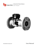
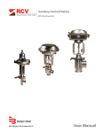
Turbine Flow Meter
1100 Series Turbine Meter
TUR-UM-00014-EN-03 (July 2014)
User Manual
Turbine Flow Meters, 1100 Series
CONTENTS
Introduction . . . . . . . . . . . . . . . . . . . . . . . . . . . . . . . . . . . . . . . . . . . . . . . . . . . . . . . . . . . . . . . . . . . . . . . . . 3
Operating Principle . . . . . . . . . . . . . . . . . . . . . . . . . . . . . . . . . . . . . . . . . . . . . . . . . . . . . . . . . . . . . . . . . . . . .3
Specifications . . . . . . . . . . . . . . . . . . . . . . . . . . . . . . . . . . . . . . . . . . . . . . . . . . . . . . . . . . . . . . . . . . . . . . . . 4
Materials of Construction . . . . . . . . . . . . . . . . . . . . . . . . . . . . . . . . . . . . . . . . . . . . . . . . . . . . . . . . . . . . . .4
Operating Parameters . . . . . . . . . . . . . . . . . . . . . . . . . . . . . . . . . . . . . . . . . . . . . . . . . . . . . . . . . . . . . . . . 4
Installation . . . . . . . . . . . . . . . . . . . . . . . . . . . . . . . . . . . . . . . . . . . . . . . . . . . . . . . . . . . . . . . . . . . . . . . . . . 4
Pressure Drop Charts . . . . . . . . . . . . . . . . . . . . . . . . . . . . . . . . . . . . . . . . . . . . . . . . . . . . . . . . . . . . . . . . . . . .7
Operational Startup . . . . . . . . . . . . . . . . . . . . . . . . . . . . . . . . . . . . . . . . . . . . . . . . . . . . . . . . . . . . . . . . . . . . 7
Turbine Replacement . . . . . . . . . . . . . . . . . . . . . . . . . . . . . . . . . . . . . . . . . . . . . . . . . . . . . . . . . . . . . . . . . . . 8
Part Number Information . . . . . . . . . . . . . . . . . . . . . . . . . . . . . . . . . . . . . . . . . . . . . . . . . . . . . . . . . . . . . . . . 10
Page ii
July 2014
Introduction
INTRODUCTION
Designed to withstand the demands of the most rigorous flow measurement applications the Model 1100 turbine flow meter
is reliable, rugged and cost effective. Originally developed for the secondary oil recovery market, the Model 1100 is an ideal
meter for liquid flow measurement on or off the oil field.
The meter features a rugged 316 stainless steel housing and rotor support assemblies, CD4MCU stainless steel rotor, and
abrasive-resistant tungsten carbide rotor, shaft, and journal bearings. The Model 1100 maintains measurement accuracy
and mechanical integrity in the corrosive and abrasive fluids commonly found in oil field water flood project and many
industrial applications.
OPERATING PRINCIPLE
Fluid entering the meter passes through the inlet flow straightener which reduces its turbulent flow pattern and improves
the fluid’s velocity profile. Fluid then passes through the turbine, causing it to rotate at a speed proportional to the fluid
velocity. As each turbine blade passes through the magnetic field, the blade generates an AC voltage pulse in the pickup coil
at the base of the magnetic pickup (see Figure 1). These pulses produce an output frequency proportional to the volumetric
flow through the meter. The output frequency represents flow rate and/or totalization of fluid passing through the turbine
flow meter.
Magnetic Pickup
or
Other Frequency
Output Device
Turbine Rotor
Output
Signal
Figure 1: Schematic illustration of electric signal generated by rotor movement
Magnetic Pick-up
* Rotor and
Rotor Shaft
Conduit Adaptor
* Upstream
Rotor Support
Meter Body
* Retaining Ring
Retaining Ring
Groove
Retaining Pins
* Downstream
Rotor Support
* Thrust Ball
* Bearing
NOTE: * Indicates parts supplied in repair kits.
Figure 2: Typical cross-section of B110-375…B111-121 turbine flow meter
July 2014
TUR-UM-00014-EN-03
Page 3
Turbine Flow Meter, 1100 Series
SPECIFICATIONS
Materials of Construction
Body
316 Stainless Steel
Rotor
CD4MCU Stainless Steel
Rotor Support
316 Stainless Steel
Rotor Shaft and
Bearing
Tungsten Carbide
Operating Parameters
–150…350° F (–101…177° C).
Temperature
The meter should not be subjected to temperatures above 350° F (177° C), or below –150° F (–101° C) or the
freezing point of the metered liquid.
Pressure
Maximum pressure ratings as follows:
5000 psi for all NPT meters up to 2 in.
3000 psi for 3 in. and 4 in. Grayloc meters.
800 psi for 3…10 in. grooved end meters.
Accuracy
±1% of reading for 7/8 in. and larger meters.
±1% of reading over the upper 70% of the measuring range for 3/8 in., 1/2 in., and 3/4 in. meters.
Repeatability
±0.1%.
Calibration
Water (NIST traceable calibration).
Approvals
“Single Seal”: ANSI/ISA 12.27.01-2003; MWP 5,000 PSI (34.5 MPa), 350° F.
I.S. Entity Parameters with Badger Meter B111109 standard magnetic pickup installed:
Vmax = 10V, Imax = 7mA, Ci = 0µF, Li = 0.9H
End Connections
NPT, BSP, Victaulic, Flange, and Hose Barbed.
*Contact the factory for ordering options.
NNOTE: Consult factory for pressure ratings for flanged meters.
INSTALLATION
PRESSURE IN EXCESS OF ALLOWABLE RATING MAY CAUSE THE HOUSING TO BURST AND CAUSE SERIOUS
PERSONAL INJURY.
AVERTISSEMENT
LA PRESSION AU-DESSUS DE L’ESTIMATION PERMISE PEUT FAIRE ÉCLATER ET CAUSER LE LOGEMENT LE DOMMAGE
CORPOREL SÉRIEUX.
1. Check the internals of the flow meter for any foreign material. Make sure the turbine rotor spins freely prior to installation.
Also, check fluid lines and remove any debris found.
2. Install the flow meter with the flow arrow, etched on the exterior of the meter body, pointing in the direction of fluid flow.
Though the meter is designed to function in any position, where possible, install it horizontally with the conduit adapter
facing upward.
3. Thread a magnetic pickup (Badger Meter model B111109 or equivalent) into the conduit adapter completely finger tight
without forcing. Secure with a lock nut if supplied.
4. Install conduit or other fittings suitable for the installation area onto the conduit adapter hub on the flow meter.
Page 4
July 2014
Installation
All Badger Meter Model 1100 turbine meters use stainless steel and tungsten carbide construction materials. Make sure the
operating fluid is compatible with these materials. Incompatible fluids can cause deterioration of internal components and
cause a reduction in meter accuracy.
The measured liquid should be free of any large particles that may inhibit rotation of the turbine blades. If particles are
present, install a mesh strainer upstream before operating the flow meter. See Table 1 for strainer recommendations.
Part Number
Strainer Mesh
Clearance
Filter Size
B110-375
60 x 60
0.0092 in.
260 μm
B110-500
60 x 60
0.0092 in.
260 μm
B110-750
60 x 60
0.0092 in.
260 μm
B110-875
60 x 60
0.0092 in.
260 μm
B111-110
60 x 60
0.0092 in.
260 μm
B111-115
20 x 20
0.0340 in.
0.86 mm
B111-120
10 x 10
0.0650 in.
1.6 mm
B111-121
20 x 20
0.0340 in.
0.86 mm
B111-130, B117-130
8x8
0.0900 in.
2.3 mm
B111-140, B117-140
10 x 10
0.0650 in.
1.6 mm
B111-160
4x4
0.1875 in.
4.8 mm
B111-180
8x8
0.0900 in.
2.3 mm
B111-200
4x4
0.1875 in.
4.8 mm
Table 1: Strainer mesh installation details
The preferred plumbing setup is one containing a bypass line (see Figure 3) that allows meter inspection and repair without
interrupting flow. If a bypass line is not used, it is important that all control valves be located downstream of
the flow meter (see Figure 4).
STRIKING AN EMPTY METER WITH HIGH VELOCITY FLOW STREAM CAN CAUSES DAMAGE.
ATTENTION
DES DOMMAGES PEUVENT ÊTRE PROVOQUÉS EN FRAPPANT UN MÈTRE VIDE AVEC UN JET D’ÉCOULEMENT DE VITESSE
ÉLEVÉE.
This is true with any restriction in the flow line that may cause the liquid to flash. If necessary, install air eliminators to ensure
that the meter is not incorrectly measuring entrained air or gas.
Badger Meter recommends installation of a minimum length, equal to ten (10) pipe diameters of straight pipe on the
upstream side and five (5) diameters on the downstream side of the flow meter. Otherwise, meter accuracy may be affected.
Piping should be the same size as the meter bore or threaded port size.
Severe pulsation and mechanical vibration affect accuracy and shorten the life of the meter. If this condition is present,
consider using a flow meter possessing superior resistance to pulsation and vibration like the Badger Meter QuicSert. Do not
locate the flow meter or connection cable close to electric motors, transformers, sparking devices, high voltage lines, or place
connecting cable in conduit with wires furnishing power for such devices. These devices can induce false signals in the flow
meter coil or cable, causing the meter to read inaccurately.
If problems arise with the flow meter, consult the Troubleshooting Guide on page 11. If further problems arise, consult
the factory.
If damaged replace the internal components of the turbine flow meter with a turbine meter repair kit available from
Badger Meter. For information pertaining to the repair kits, see Turbine Replacement on page 8.
July 2014
TUR-UM-00014-EN-03
Page 5
Turbine Flow Meter, 1100 Series
1
2
Electronic
Flow Monitor
Isolation and
Flow Rate
Control Valve
Isolation Valve
10 Pipe
Diameters
Turbine
Flow Meter
5 Pipe
Diameters
Bypass Valve
Figure 3: Meter installation with a bypass line
1
2
Electronic
Flow Monitor
Control Valve
10 Pipe
Diameters
Turbine
Flow Meter
5 Pipe
Diameters
Figure 4: Meter installation without a bypass line
Page 6
July 2014
Pressure drop charts
PRESSURE DROP CHARTS
Pressure Drop vs Flow Rate
30
Pressure Drop vs Flow Rate
2
1/2”
3/8”
3/4”
1
1-1/2”
7/8”
1”
2”
3”
4”
6”
8”
Pressure Drop Bar
Pressure Drop PSID
1
10
10”
3/4”
3/8”
1”
7/8”
1/2”
0.1
1-1/2”
2”
3”
4”
6”
8”
10”
0.01
0.1
0.005
0.5 1
10
(17) (34)
(343)
100
(3429)
1000
(34,286)
8000
(274,236)
1
(1.44)
10
(14.4)
100
(144)
1000
(1440)
10,000
(14,400)
Flow Rate LPM (m³/Day)
Flow Rate GPM (BPD)
Figure 5: English units pressure drops
30,000
(57,600)
Figure 6: Metric units pressure drops
OPERATIONAL STARTUP
Follow these steps when installing and starting the meter.
MAKE SURE TO SHUT OFF FLUID FLOW AND RELEASE PRESSURE IN THE LINE BEFORE ATTEMPTING TO INSTALL THE
METER IN AN EXISTING SYSTEM.
AVERTISSEMENT
ASSUREZ-VOUS QUE LE FLUX DE FLUIDE A ÉTÉ COUPÉ ET DE LA PRESSION DANS LA LIGNE A ÉTÉ LIBÉRÉE AVANT
D’ESSAYER D’INSTALLER LE MÈTRE DANS UN SYSTÈME ACTUEL.
After meter installation, close the isolation valves and open the bypass valve. Allow liquid to flow through the bypass valve for
sufficient time to eliminate any air or gas in the flow line.
HIGH VELOCITY AIR OR GAS MAY DAMAGE THE INTERNAL COMPONENTS OF THE METER.
ATTENTION
DES DOMMAGES PEUVENT ÊTRE PROVOQUÉS EN FRAPPANT UN MÈTRE VIDE AVEC UN JET D’ÉCOULEMENT DE VITESSE
ÉLEVÉE.
5. Open the upstream isolating valve slowly to eliminate hydraulic shock while charging the meter with the liquid. Open the
valve to full open.
6. Open downstream isolating valve to permit meter to operate.
7. Close the bypass valve to a full closed position.
8. Adjust the downstream valve to provide the required flow rate through the meter.
NNOTE: If necessary, use the downstream valve as a control valve.
July 2014
TUR-UM-00014-EN-03
Page 7
Turbine Flow Meter, 1100 Series
TURBINE REPLACEMENT
The Model 1100 turbine flow meter uses wear resistant moving parts to provide trouble-free operation and long service life.
The Designed for easy field service of a damaged flow meter Model 1100 repair kits replace only the internal parts, rather than
replacing the entire flow meter. Repair parts use stainless steel alloys and tungsten carbide construction materials.
Each repair kit is factory calibrated to ensure accuracy throughout the entire flow range. Each kit is complete and includes
a new K factor, which is the calibrated number of pulses generated by each gallon of liquid. Recalibration of the monitor or
other electronics uses the K factor to provide accurate output data.
NNOTE: If the meter repair kit part number ends in NCC (no calibration), it was not factory calibrated. For these repair kits, use
the nominal K factor.
Turbine Replacement Kit Part Number
Flow Meter Size
Replacement Kit Fits
Meter Part Number
Repair Kit Part Number
3/8 in.
B110-375, B110-375-1/2
B251-102
1/2 in.
B110-500, B110-500-1/2
B251-105
3/4 in.
B110-750, B110-750-1/2
B251-108
7/8 in.
B110-875
B251-109
1 in.
B111-110
B251-112
1-1/2 in.
B111-115
B251-116
2 in. Low
B111-121
B251-116
2 in.
B111-120
B251-120
3 in.
B111-130
B251-131
4 in.
B111-140
B251-141
6 in.
B111-160
B251-161
8 in.
B111-180
B251-181
10 in.
B111-200
B251-200
Standard Magnetic Pick-up
All Meter Sizes
B111109
Table 2: Repair kit part numbers
Turbine Assembly Removal
HIGH-PRESSURE LEAKS ARE DANGEROUS AND MAY CAUSE PERSONAL INJURY. MAKE SURE TO SHUT OFF FLUID FLOW
AND RELEASE RESIDUAL PRESSURE IN THE LINE BEFORE ATTEMPTING TO REMOVE THE METER.
AVERTISSEMENT
LES FUITES À HAUTE PRESSION SONT DANGEREUSES ET PEUVENT CAUSER LE DOMMAGE CORPOREL. ASSUREZ-VOUS
QUE LE FLUX DE FLUIDE A ÉTÉ COUPÉ ET DE LA PRESSION DANS LA LIGNE A ÉTÉ LIBÉRÉE AVANT D’ESSAYER D’ENLEVER
LE MÈTRE.
Page 8
July 2014
Turbine replacement
Disassembly
Refer to Figure 7, Figure 8 and Figure 9 for relative positions of repair kit components.
Remove the magnetic pickup from the meter body to avoid damage during repair.
Remove the retaining ring from one end of the meter.
Remove the rotor support from the body. If the rotor support is jammed in the body, use a pair of pliers or vise-grips to
break the rotor support free.
5. The rotor may also be removed at this time.
NNOTE: 4 in. and larger meters have two retaining rings (one on either side of the rotor) that require removal before the rotor
can be removed (see Figure 9).
6. Remove the retaining ring from the opposite side of the meter.
7. Remove the second rotor support.
1.
2.
3.
4.
Magnetic
Pick-up
Retaining Ring
Groove
Retaining Ring
Groove
Rotor
Assembly
Flow Direction
Arrow
Flow Direction
Arrow
FLOW
Upstream
Rotor Support
Flow Direction
Arrow
Downstream
Rotor Support
Flow Meter
Body
Retaining Ring
Retaining Ring
Flow Direction
Arrow
Figure 7: Component positions for B110-375…B111-115 and B111-121
Retaining Ring
Groove
Flow Direction
Arrow
Upstream
Rotor Support
Magnetic
Pick-up
Retaining Ring
Groove
Downstream
Rotor Support
FLOW
Flow Direction
Arrow
Retaining Ring
Flow Direction
Arrow
Rotor
Assembly
Flow Meter
Body
Retaining Ring
Flow Direction
Arrow
Figure 8: Component positions for B111-120 and B111-130
Flow Direction
Arrow
Retaining Ring
Grooves
Magnetic
Pick-up
Retaining Ring
Grooves
Upstream
Rotor Support
Downstream
Rotor Support
FLOW
Flow Direction
Arrow
Rotor
Assembly
Flow Meter
Body
Flow Direction
Arrow
Retaining Ring
Flow Direction
Arrow
Retaining Ring
Retaining Ring
Retaining Ring
Figure 9: Component positions for B111-140 and B111-200
July 2014
TUR-UM-00014-EN-03
Page 9
Turbine Flow Meter, 1100 Series
New Turbine Kit Installation
IIMPORTAN
Before reassembly, note that an arrow is cast or engraved on each component. The arrow indicates the primary flow direction. When
reassembled, the arrowheads must point in the direction of the fluid flow. The arrows must also be oriented in the up position on
both rotor supports. The magnetic pickup side of the body signifies the up position. Performance of repair kit calibration is in the up
position. Reinstallation of the repair kit in the up position ensures continuation of accurate measurements. Figure 7, Figure 8, and
Figure 9 show the proper alignment and orientation of the repair kits.
NNOTE: Fractional size (3/8 in., 1/2 in. and 3/4 in.) rotors do not contain a cast or engraved arrow. However, a colored cap
on the downstream side of the rotor shaft indicates flow direction. Remove this cap before assembly, noting
flow direction.
1. Install one of the rotor supports into the body bore, noting the orientation of the arrow.
2. Secure a retaining ring in the groove provided. Check for complete installation of retaining rings in each groove.
NNOTE: 4 in. and larger meters have a retaining ring at both ends of the rotor (see Figure 9).
3. Insert the rotor and second rotor support in the opposite side of the body, noting the orientation of the arrow.
4. Secure the second retaining ring in the opposite groove, using the same procedure as in step 2 above.
EXCESS AIR PRESSURE MAY DAMAGE THE ROTOR AND BEARINGS BY OVER SPINNING.
ATTENTION
LA PRESSION ATMOSPHÉRIQUE EXCESSIVE PEUT ENDOMMAGER LE ROTOR ET LES ROULEMENTS PRÈS AU-DESSUS DE
LA ROTATION.
5. Check the meter by lightly puffing air through the assembly. If the rotor does not turn freely, disassemble the meter and
remove anything that might obstruct movement of the rotor.
NNOTE: At this time, electronics require recalibration. Refer to the display's user manual. If there are any questions on
recalibration, contact Badger Meter, Inc. or the manufacturer of the associated electronics.
6. Install the magnetic pickup.
PART NUMBER INFORMATION
End to End Length
Meter Size
inches
mm
gpm
bpd
m³/d
B110-375-1/2
B110-500-1/2
B110-750-1/2
3/8 in.
1/2 in.
3/4 in.
3
3
3
76.2
76.2
76.2
1/2 in. Male NPT
1/2 in. Male NPT
1/2 in. Male NPT
0.6…3.0
0.75…7.5
2…15
20…100
25…250
68…515
3.3…16
4.1…41
10.9…81.75
B110-375
3/8 in.
4
101.6
1 in. Male NPT
0.6…3.0
20…100
3.3…16
B110-500
B110-750
B110-875
B111-110
B111-115
B111-121
B111-120
B111-130
1/2 in.
3/4 in.
7/8 in.
1 in.
1-1/2 in.
2 in. Low
2 in.
3 in.
4 in.
6 in.
8 in.
10 in.
4
4
4
4
6
6
10
12-1/2
12
12
12
12
101.6
101.6
101.6
101.6
152.4
152.4
254
317.5
304.8
304.8
304.8
304.8
1 in. Male NPT
1 in. Male NPT
1 in. Male NPT
1 in. Male NPT
1-1/2 in. Male NPT
2 in. Male NPT
2 in. Female NPT
3 in. Grooved End
4 in. Grooved End
6 in. Grooved End
8 in. Grooved End
10 in. Grooved End
0.75…7.5
2…15
3…30
5…50
15…180
15…180
40…400
60…600
100…1200
200…2500
350…3500
500…5000
25…250
68…515
100…1000
170…1700
515…6000
515…6000
1300…13,000
2100…21,000
3400…41,000
6800…86,000
12,000…120,000
17,000…171,000
4.1…41
10.9…81.75
16…160
27.25…272.5
82…981
82…981
218…2180
327…3270
545…6540
1090…13,626
1363…19,076
2725…27,252
B111-140
B111-160
B111-180
B111-200
Page 10
End Connection
Flow Ranges
Part Number
July 2014
Part number information
TROUBLESHOOTING GUIDE
Trouble
Possible Cause
Meter indicates higher than actual flow rate
Cavitation.
Debris on rotor support.
Build up of foreign material on meter bore.
Gas in liquid.
Increase back pressure.
Clean meter.
Clean meter.
Install gas eliminator ahead of meter.
Meter indicates lower than actual flow rate.
Debris on rotor.
Worn bearing.
Viscosity higher than calibrated.
Clean meter and add filter.
Clean meter and add filter.
Recalibrate monitor.
Erratic system indication, meter alone works
well (remote monitor application only).
Ground loop in shielding.
Ground shield one place only. Look for
internal electronic instrument ground.
Reroute cables away from electrical noise.
Indicator shows flow when shut off.
Mechanical vibration causes rotor to
oscillate without turning.
Isolate meter.
No flow indication.
Full or partial open position.
Fluid shock, full flow into dry meter or
impact caused bearing separation or
broken rotor shaft.
Rebuild meter with repair kit and recalibrate
monitor. Move to location where meter
is full on startup or add downstream flow
control valve.
Erratic indication at low flow, good
indication at high flow.
Rotor has foreign material wrapped around
it.
Clean meter and add filter.
No flow indication.
Faulty pickup.
Replace pickup.
System works perfect, except indicates
lower flow over entire range.
By-pass flow, leak.
Repair or replace bypass valves, or faulty
solenoid valves.
Meter indicating high flow, upstream piping
at meter smaller than meter bore.
Fluid jet impingement on rotor.
Change piping.
Meter indicating low flow, upstream piping
at meter smaller than meter bore.
Viscosity lower than calibrated.
Change temperature, change fluid or
recalibrate meter.
July 2014
TUR-UM-00014-EN-03
Remedy
Page 11
Control. Manage. Optimize.
Blancett is a registered trademarks of Badger Meter, Inc. Other trademarks appearing in this document are the property of their respective entities. Due to continuous research,
product improvements and enhancements, Badger Meter reserves the right to change product or system specifications without notice, except to the extent an outstanding
contractual obligation exists. © 2014 Badger Meter, Inc. All rights reserved.
www.badgermeter.com
The Americas | Badger Meter | 4545 West Brown Deer Rd | PO Box 245036 | Milwaukee, WI 53224-9536 | 800-876-3837 | 414-355-0400
México | Badger Meter de las Americas, S.A. de C.V. | Pedro Luis Ogazón N°32 | Esq. Angelina N°24 | Colonia Guadalupe Inn | CP 01050 | México, DF | México | +52-55-5662-0882
Europe, Middle East and Africa | Badger Meter Europa GmbH | Nurtinger Str 76 | 72639 Neuffen | Germany | +49-7025-9208-0
Europe, Middle East Branch Office | Badger Meter Europe | PO Box 341442 | Dubai Silicon Oasis, Head Quarter Building, Wing C, Office #C209 | Dubai / UAE | +971-4-371 2503
Czech Republic | Badger Meter Czech Republic s.r.o. | Maříkova 2082/26 | 621 00 Brno, Czech Republic | +420-5-41420411
Slovakia | Badger Meter Slovakia s.r.o. | Racianska 109/B | 831 02 Bratislava, Slovakia | +421-2-44 63 83 01
Asia Pacific | Badger Meter | 80 Marine Parade Rd | 21-06 Parkway Parade | Singapore 449269 | +65-63464836
China | Badger Meter | 7-1202 | 99 Hangzhong Road | Minhang District | Shanghai | China 201101 | +86-21-5763 5412
Legacy Document Number: 02-TUR-UM-00103-EN