1
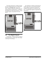
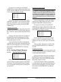
The 168DO has no hardware-based fail-safe
settings (fail-safes are set up in the board firmware). All that is required is to connect the “+”
terminal to the positive wire on the device and
the “-” terminal to the negative (or ground) wire
of the device.
DIGITAL
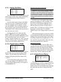
The analog outputs have no hardware-based
fail-safe settings (fail-safes are set in the board
firmware; see Section 6.1.9., Analog FailSafes). All that is required to connect a device to
an analog point is to connect the “+” terminal to
the positive wire on the device and the “-” terminal to the negative (or ground) wire of the
device.
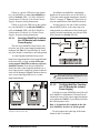
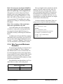
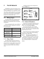
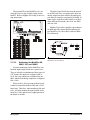
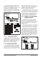
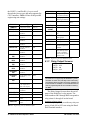
Figure 4-7 - MultiFlex Digital Points
Figure 4-6 - MultiFlex Analog Points
4.4.
The Digital Outputs
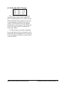
The MultiFlex 168DO board has four digital
outputs that pulse a +8VDC signal. Each output
is rated up to 10 milliamps.
The Digital Outputs
I/O Board Input and Output Setup • 15