1
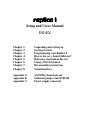
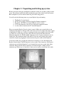
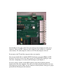
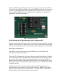
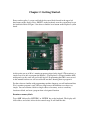
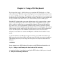
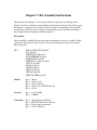
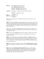
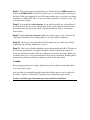
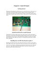
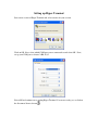
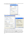
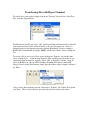
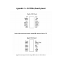
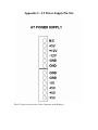
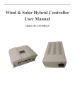
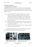
Setup and Users Manual
Revision C
JANUARY 2005
5392 Cornell Blvd
North Ridgeville, OH 44039
Copyright 2005 Briel Computers All Rights Reserved
Setup and Users Manual
INDEX
Chapter 1:
Chapter 2:
Chapter 3:
Chapter 4:
Chapter 5:
Chapter 6:
Chapter 7:
Chapter 8:
Unpacking and setting up
Getting started
Programming your Replica I
How is the rev c board different?
Reference material on the net
Using a PS/2 keyboard
Kit assembly instructions
Serial Interface
Appendix A:
Appendix B:
Appendix C:
ASCII Keyboard pin out
Onboard jumper and NVRAM
Power supply connector
Chapter 1: Unpacking and Setting up system.
Before you begin setting up your Replica I computer, make sure you have plenty of table
space. Do not power up the unit while touching any part of the circuit board and contact
Briel computers if you are unsure about any part of the setup process.
You will need the following items to get your Replica I up and running:
1.
2.
3.
4.
5.
The Replica I system board.
AT PC power supply (like those found in Pentium computers).
Keyboard, a PC PS/2 or an Apple II/II plus (not //e or //gs).
A TV with composite video in, or a composite computer monitor.
A video cable to attach to the TV from the Replica 1.
Place or mount the Replica I board so that it secured. Make sure no metal objects can
touch the circuit board or damage could result. Next you need to plug in the power supply
to the Replica I. Make sure you have not plugged in the power supply to the wall socket
yet. There are several groups of wires, and you need to locate the 2 that stand out
differently from the rest. The P8 and P9 connectors are the 2 square connectors you are
looking for. They should be labeled, P8 and P9. You can verify you have the correct
connectors simply by plugging the connector into the power socket of the Replica I.
You need to make sure you plug the connectors in correctly or you could damage the
Replica I circuit board. The P9 connector is closer to the Video connector. If the power
connectors are not labeled then the 2 sets of ground wires are next to each other when
connected. Plug in the P8 and P9 connectors as shown in Figure 1. Make sure the
connectors go all the way on. Once this is done, you are ready to install the video cable.
Typical AT-style power supply found in 386-Pentium computers
Figure 1 Power connector with P8 and P9 labeled
Attach an RCA video cable to the Video out connector located right next to the power
connector. This is an NTSC composite video signal. You can attach it to a composite
video monitor, TV with composite video in or a VCR with composite video in.
Do not turn on the TV until the setup procedures are complete.
Now you can attach either a standard PS/2 PC keyboard, or an Apple II/IIplus ASCII
keyboard. You may use one or the other type but you CANNOT use both types at the
same time. Attempting to do so may result in damage to your Replica I.
If you are going to attach a standard PS/2 keyboard, locate the keyboard connector
located next to the video connector. The cable end of the keyboard should have an arrow
indicating the up position. Make sure the connector on the keyboard is facing in its proper
position before inserting into the connector.
If using an ASCII or Apple II keyboard, make sure to plug the cable in properly. Pin 1 is
closer to the edge of the board. Figure 2 shows the ASCII keyboard port. If you have any
questions regarding installation of the Apple II keyboard, feel free to email or write. If
you are using an ASCII keyboard not designed for the Apple II refer to Appendix A
regarding the correct pin out required.
Figure 2 ASCII Keyboard port
NOTE: If using the ASCII keyboard port, place a jumper on JP1.
Mount the switch on the AT power supply so that when you turn on the replica, you only
touch the switch and no wires. Make sure the power supply is turned off before plugging
in. Now you can plug in the power connector to the power supply and to the wall socket.
Powering up your Replica 1.
Your Replica I system is now ready to turn on. Make sure you take all necessary
precautions to avoid electrical shock
Turn on the TV or Monitor and then turn on the power supply for the Replica I. A block
cursor should appear in the bottom left corner of the screen. If you do not get this block
cursor, power the computer back off and recheck all of your connections. While the
Replica I was tested with several monitors and Televisions, it is not guaranteed to work
on all types. If you are having problems getting a proper picture on the TV, write to Briel
Computers for help.
At this point the system is powered on but just like the Apple I a reset needs to be
performed before the computer will begin operation. Press the ‘RESET’ button on the
keyboard and the Replica I should respond with a ‘\’ backslash character followed by a
linefeed and the cursor should now be below the backslash.
Chapter 2: Getting Started.
Power on the replica 1 system, and look for the cursor block located in the upper left
hand corner of the display. Press ‘RESET’ on the keyboard or on the system board to get
the backslash. Refer to Figure 3 for where to find the reset button on the Replica I system
board.
Figure 3 reset switch on Replica I system board
At this point you are in Woz’s monitor program written for the Apple I. The monitor is a
simple way to be able to program the Replica 1. The Replica I is designed with the 6502
microprocessor, the same one used in the Apple I. Programming the 6502 is not covered
in this manual but there are still several books out there showing how to program it.
For those that are familiar with programming machine language you will understand that
Woz’s monitor program is only 256 bytes long because the functions were kept very
simple. You can examine a block or single address of memory, write to a memory
location or block, and start a program from a designated location.
Examine a memory block:
Type ‘0.2F’ followed by ‘RETURN’ or ‘ENTER’ key on the keyboard. The display will
show address and values in hex for the entered range. It will look like this:
0000: 00 01 03 D0 00 00 05 A0
0008: DF 07 00 00 0C 01 01 11
0010: 00 01 03 D0 00 A0 50 00
0018: CF C0 70 10 11 01 01 01
0020: 00 30 D0 80 C1 11 11 11
0028: 10 00 30 0D 05 A0 00 00
Examining a block will display 8 bytes across the page. The display always cuts off at set
addresses so the next line starts with a ‘0’ or an ‘8’. If you started with a 1 or some other
address other than a ‘0’ or an ‘8’ then the first row of memory listed will cut off with the
address ending in ‘7’ or ‘F’. For example if you type ‘1.F’ it will display like this:
0001: 01 03 D0 00 00 05 A0
0008: DF 07 00 00 0C 01 01 11
Notice how the first line only shows 7 bytes of memory? This is so that the listing comes
out uniform.
Change or write to a memory location:
Typing in ‘0:FF’ will change the memory at location 0 to the hex value FF. The monitor
will respond with the memory location you changed and the old value.
Example:
You type: ‘0:FF’ [RETURN]. The monitor responds with:
0: 00 (The old contents of the memory location)
To change a block address range from 0100-0105 type:
‘100:4C EE FF 0A 60 60” followed by ‘RETURN’ The display will show the old
contents of memory location ‘0’. Then you may view your changes by typing in ‘0.5’
followed by ‘RETURN’.
Run a program in memory:
To run a program you have entered into memory, type in the address followed by ‘R’ and
press ‘RETURN’. Example, to start a program that you have entered starting at memory
location 0300 type ‘300R’ followed by ‘RETURN’.
More examples of the use of the use of the monitor can be found in the Apple I users
manual. See Chapter 5: Reference material for the Apple I, for where you can
download a copy of the original Apple I manual.
Chapter 3: Programming your Replica 1
There are a couple of ways you can program your Replica I. One way is to enter machine
language programs from Woz’s monitor program and run them as described in Chapter 2.
There are sites dedicated to the 6502 such as http://www.6502.org, which supports the
processor for development and experimenting, has information available on how to
program the CPU, and has discussion groups for help.
Integer Basic:
Another way would be to program in Woz’s Integer Basic. It is at location $E000. Simply
power up the Replica I, press reset, and type ‘E000R’ followed by ‘RETURN’. Refer to
the Apple 1 preliminary Basic manual at Applefritter for programming in Integer Basic.
Saving your programs:
A serial interface I/O board is available to store and load programs from a PC or Mac. If
you do not wish to use a serial interface, there is another method that you can use:
A simple solution used has been to replace the 62256 Static RAM IC with a Non-volatile
SRAM IC such as the Dallas DS130Y-120. This will store your programmed
information even when the power is turned off and has a 10 year life-span. If you are not
familiar with working with IC’s do not perform this function or seek assistance from
someone with knowledge on how to exchange IC’s as damage may occur to the Replica I
if not done properly.
Chapter 4: How is the rev c board different?
Appearance:
The revision c board is very similar and almost exactly the same as the prior revision
boards. The main difference is the addition of a clear screen key. This key allows the user
to clear the screen at any given time without interrupting the computer. The other
difference is only 1 jumper is now required for setting the type of keyboard you use.
There is now written instructions on how to set the jumpers for the proper keyboard. The
jumper posts for external reset and external clear screen buttons are not installed but can
be hard wired to the board if the user wishes to use that option.
Function:
The revision c functions completely identical as the former revision with a few small
improvements. The most noticeable is that the cursor now starts at the top of the screen
instead of the bottom. This was not included with the original release of the replica as
implementing this function was a difficult feature and there was not enough time to
install before the release of the replica. This is a more accurate detail of how the apple 1
operated.
Another added feature is the addition of the clear screen button on the board. The apple 1
had the option of clearing the screen if the keyboard used had a clear screen key. Now,
pressing this button clears the screen for you.
A single capacitor was added to fix a video bug which caused characters to not be
displayed.
Enhanced keyboard keys added for ps/2 keyboards. The numeric keypad on ps/2
keyboards is now able to be used. Originally I didn’t add these keys because they were
not on most ASCII keyboards, but when I added the clear screen key option, it was easy
to add the whole keypad option. The END key will clear the screen and HOME will put
the cursor at the top. While the clear screen key was available on the original apple 1, the
home cursor option was not but I added it as an extra feature that doesn’t take away from
the feel of the apple 1.
Chapter 5: Reference Material on the Internet
Apple I related information:
The preservation of Apple I documents, software, manuals and source code is the duty
the Apple I users club has taken on. At http://www.applefritter.com/apple1/ you can find
all documents submitted by Apple I owners as well as stories, pictures and other
information. There is also a forum to discuss the Apple I as well as the Replica I.
6502 CPU related information:
There is a user group at http://www.yahoo.com for the 6502.
Also http://www.6502.org is an information rich site for anything related to the 6502
CPU and support hardware. There is also a discussion group to help with questions.
Apple I history:
http://www.apple-history.org has a very nice page on the Apple I including ads and
pictures. Of course, http://www.applefritter.com has the original Apple 1 users group and
almost everything you can think of for your replica.
Software:
The restoration of authentic Apple I software is continuing daily. Please visit Briel
Computers’ website for more information on currently available software and for
information on how to help archive your programs. Many programs for the Apple 1 have
been recovered but there are still some programs out there that has not been saved.
http://www.vintagecomputer.tk
Chapter 6: Using a PS/2 Keyboard
The design of the Apple 1 called for the user to attach an ASCII keyboard to a 16 pin
socket on the board. When the design of the Replica I was nearing finishing stages, it too
just had an ASCII keyboard port. The problem is, this type of keyboard is no longer being
produced and they are becoming more difficult to locate. Therefore a special encoder was
developed which would allow the use of a standard PC keyboard on the Replica 1.
While the PC keyboard takes away some of that vintage feel, it opens the door so more
people can use the Replica I. Due to the complex nature of the PS/2 keyboards signal
process, only the standard keys are programmed to function. That means the function
keys, arrow keys, are not programmed to function. The revision c board now adds the
ability to use the numeric keypad on ps/2 keyboards. This was done because of a redesign
of the keyboard encoder on the replica. The only key that is not on a PS/2 keyboard that
was on ASCII keyboards is the “RESET” button. Because of the need for a PS/2
keyboard, a reset button was added to the Replica I so that the circuit could be reset as
needed.
As with normal PC use, the Replica I supports auto key repeat. This means that if you
hold down a key after a short while it will auto repeat. So, make sure you are careful not
to be holding down a key for too long since the replica 1 has only the underscore for a
backspace.
CAUTION:
Do not attempt to use a PS/2 keyboard if you have an ASCII keyboard attached to the
Replica 1; doing so could damage the board and void the warranty.
As mentioned before, do not plug in or unplug the PS/2 keyboard while power is turned
on; doing so could damage the board.
Chapter 7: Kit Assembly Instructions
The kit form of the Replica 1 is for people who have experience in soldering circuit
boards. If you have experience with soldering circuit boards, then not only will you enjoy
the Replica 1 computer, but you will also have the pride in assembling it yourself while
saving money. If you have never built a circuit board kit, please start with something a
little simpler before attempting to build the replica 1.
Kit contents:
I have carefully assembled all parts into separate containers for ease of assembly. Check
each bag to ensure that all parts are there. If you find anything missing, please contact
Briel Computers.
IC’s:
6502 or 65C02 CPU 40 pin IC
6821 40 pin IC
ATMEGA8515 40 pin IC
28C64 EEPROM 28 pin IC
62256 SRAM 28 pin IC
ATMEGA8 28 pin IC (narrow)
74LS138 16 pin IC
74LS04 14 pin IC
74LS00 14 pin IC
74HC74 14 pin IC
74HC166 16 pin IC
CRYSTAL 1MHz 4 pin IC
Sockets:
Qty 3 – 40 pin
Qty 2 – 28 pin (wide)
Qty 1 – 28 pin (narrow)
Qty 3 – 16 pin (1 for ASCII keyboard)
Qty 3 – 14 pin
Crystals:
Qty 1 – 14.31818Mhz
Qty 1 – 8.0MHz
Connectors: Qty 1 – 40 pin Expansion Header
Qty 1 – DIN PS/2 Keyboard connector
Qty 2 – Power supply connectors
Qty 1 – Video Connector
Resistors:
R1 – 470 Ohm (yellow, violet, brown)
R2– 1.5K Ohm (brown, green, red)
R3 – 100 Ohm (brown, black, brown)
R4 & R5 – 4.7K Ohm (yellow, violet, red)
R6 – R10 – 3.3K Ohm (orange, orange, red)
Capacitors: C1, C2, C4, C5 – 18pF (newer revision C are now 22pF)
C3 - .1uF
C6 – C17 - .1uF Bypass capacitors
C18-.01uF
Diodes:
D1 & D2-1N4148
Misc. Parts: 2 Switches
1 Jumper Pad
Here is an example of the steps used to build the replica 1. You may choose to do it a
different way.
Step 1: Start with the resistors. Carefully bend the wire ends so that the resistor will fit
neatly into its designated place on the board. The board shows the resistor number as well
as its value. Solder each one onto the board using standard procedures for soldering on a
circuit board. Trim the extra length off of each one. The resistor can face either way, but I
prefer a uniform look.
Step 2: Next solder in the two diodes using the same procedure as the resistors. The
only difference is the direction does matter. The black strip on the diode should be closer
to the edge of the board.
Step 3: Solder in the capacitors using the same procedure as with the resistors. There
is no direction required to install these, but once again, uniformity is best. Trim extra
length off of the leads.
Step 4: After the capacitors are installed begin soldering in the sockets. The board
designates pin one with a square pin. The sockets also have a pin one and you can usually
tell the top of the socket with a curve in the top. Use caution when soldering so that no
extra solder connects two pins that should not be connected. The 16pin duel swipe socket
is for the ASCII keyboard.
Step 5: Once all sockets are properly soldered, install the 1MHz crystal IC. The sharp
edge corner designates pin 1. Make sure it is the closest corner to the RAM and EPROM
IC’s.
Step 6: Install the 40-pin Expansion Interface Header, the reset switch, and the
jumper header. The expansion header is probably the most difficult part to install. The
pins on the Expansion Interface Header are close like the IC’s so use caution when
installing. No pins on the header should contact each other. The switch can only be
installed in 2 directions, and either way will work.
Step 7: The crystals must be installed with care. The barrel shaped 8MHz crystal goes
next to the ATMEGA8515 and should be folded over so it lays down just to the edge of
the board. Trim extra length off of leads. The jumper header goes next to the reset switch
and where it is labeled JP1. This is so you can add an external reset switch to a case. JP1
is for keyboard selection.
Step 8: Next install the video connector. It can only be installed one way and there is
no room for error. Be sure to use enough solder to get a good connector on the tabs. Do
not trim the tabs, but you can give them a slight bend outwards prior to soldering for
better contact.
Step 9: Install the Power connectors. Make sure the flat support edge is closer to the
edge of the circuit board. Use enough solder to cover the contacts completely.
Step 10: Check over your work and look for incomplete or low solder spots. Using a
magnifying lens will help with hard to see areas.
Step 11: Once you are finished checking you can begin installing the IC’s. The pins on
IC'
s from the manufacturer are angled out slightly for good contact in the socket. So
when you install them into the socket use caution not to bend any of the pins. Make sure
you know where pin 1 is and you install the IC in the correct orientation. Installing the IC
in the incorrect direction could cause damage to the IC or the entire board.
Caution:
Before plugging in the power supply, keyboard and video connector, thoroughly check
over your work for errors.
Any parts that get accidentally damaged during the building process can be replaced at
the owner’s expense. Contact Briel Computers for any replacement parts needed.
Use the rest of this page to document any notes needed for installation
Chapter 8: Serial I/O board
Getting started
Setting up and installing the serial I/O board is easy, and only involves a few steps to get
started. First, you must disconnect all power connectors from your replica I. Next,
remove the video connector and your keyboard connector. Locate the IC labeled “6821”
on the board. Carefully using a small screw driver, remove the IC as shown in the picture
below.
Install the 6821 on the serial I/O board
Using the 6821 IC you just removed from your replica I, place it in the socket labeled
6821 on the serial I/O board. The notch in the front of the IC indicates the top of the 6821
and should be next to the “6821” label on the I/O board. Make sure all pins are straight
before applying pressure. Make sure all pins are seated properly in the socket as shown
before continuing.
Installing the serial I/O board on the replica I
Install the serial I/O board in the socket where the 6821 IC was located on your replica I
board. Make sure the serial 9 pin port faces the same direction as your video connector. If
needed; you can add plastic mounting support but I have found it unnecessary. Reattach
your power, video and keyboard. Next attach a DB-9 serial cable (non-null modem)
between your PC and the serial I/O board.
Setting up Hyper Terminal
Start a new session of Hyper Terminal and select a name for your session.
Click on OK. Next, select which COM port you are connected to and select OK. Next,
set up your COM port as shown: 2400, N,8,1
Select OK and continue on to starting Hyper Terminal. You are not ready yet, so click on
the disconnect Icon as shown:
Next, click on “File” in the menu bar and select “Properties” from the drop-down menu
list. You should then get a screen that looks like this:
Click the “Settings” tab at the top, then select the “ASCII setup” button.
Set up your settings exactly as shown in the picture above. Select “OK” to close the
ASCII Setup screen. Select “OK” again to close the properties window and return to
Hyper Terminal. Now click on the “Connect” button
and you are connected. Power
up your replica and press the reset button. Try typing on both the replica keyboard and
your pc keyboard to verify that both function. If you have any problems repeat these
steps.
Transferring files with Hyper Terminal
To send a file to your replica, simply click on the “Transfer” tab and select “Send Text
File” from the drop down list.
Find the file on your PC and select “OK”. At this point Hyper Terminal will send the file
your replica and your replica will treat the file as if you were typing it in. Once it is
finished typing in, just run your program as normal. Remember, if you are sending a
BASIC file to enter BASIC by typing “E000R” followed by “Enter” before sending the
file.
To receive a file is just as easy. Once again, click on the “Transfer” tab, but this time
select “Capture Text…” from the drop down list. This will bring up a file name to save
option and select the name for your file. Select “OK” to begin the “Capture” mode. If
you’re in BASIC you can type LIST and Hyper Terminal will capture your BASIC
listing. If you’re in the Woz monitor, simply type the address range to capture, followed
by “Enter.”
Once you are done capturing your file, click on the “Transfer” tab, Capture Text option
and “Stop.” That’s it, you can now, go in and edit your file with any text editor.
Appendix A: ASCII Keyboard pin out
Replica I keyboard port from the 16 pin DIP connector. Pin 1 is 5V.
Apple 1 keyboard port from the 16 pin DIP connector. Pin 1 is Reset.
Appendix B: Onboard jumper and NVRAM
NVRAM IC may be used in place of the SRAM IC. One such IC is the Dallas DS130Y120 found at http://www.digikey.com for around $21. Using NVRAM will allow
programs to remain in the system even while power is off. One thing to note is resetting
the system and power off can change a memory location. I try not to reset the circuit
while it is running a program.
There is now just 1 jumper on the Replica I main board next to the ATMEGA8515
keyboard controller. The default setting is for a PS/2 keyboard with no jumper installed.
If however, you wish to use an ASCII keyboard attach the jumper onto JP1. This disables
the ATMEGA8515 keyboard encoder for the PS/2 so that you can use an ASCII parallel
keyboard.
Appendix C: AT Power Supply Pin Out
The +5V pins are closer to the Video Connector on the Replica 1.
Warranty
(applies to assembled version only)
Briel Computers hereby warrants each of its products, and
all components therein contained, to be free from defects
in materials and/or workmanship for a period of thirty (3O)
days from date of purchase. In the event of the occurrence
of malfunction or other indication of failure attributable
directly to faulty workmanship and/or material, then, upon
return of the product to Briel Computers, at 5392 Cornell
Blvd, North Ridgeville, Ohio 44039 (postage prepaid), Briel
Computers will, at its option, repair or replace said
products or components thereof, to what ever extent Apple
Computer Company shall deem necessary, to restore said
product to proper operating condition. All such repairs or
replacements shall be rendered by Briel Computers, without
charge to the customer. The responsibility for the failure
of any Briel Computer product, or component thereof, which,
at the discretion of Briel Computers, shall have resulted
either directly or indirectly from accident, abuse, or
misapplication of the product, shall be assumed by the
customer, and the Apple Computer Company shall assume no
liability as a consequence of such events under the terms
of this warranty. While every effort, on the part of Briel
Computers, is made to provide clear and accurate technical
instruction on the use, implementation, and application of
its products, Briel Computers shall assume no liability in
events which may arise from the application of such
technical instruction, nor shall Briel Computers be held
liable for the quality, interconnection, or application of
peripheral products, which may have been recommended by
Briel Computers, but which have not been supplied as part
of the product. This warranty contains and embodies the
limits of responsibility of Briel Computers, with regard to
its products, and no other liability is expressed, implied,
or should be assumed by the purchaser, and in no event
shall Briel Computers be held liable for the loss of time,
effort, or transportation costs, nor for loss of potential
profits or other consequential losses which might arise
from the purchase, assembly, use, application, or
subsequent sale of the products of Briel Computers, nor
from any instructions and/or technical information thereto
related.