1
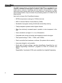
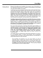
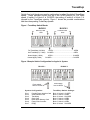
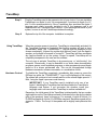
TransWarp
_
About This Manual
This manual tells you all about installing and using the Applied Engineering
TransWarp accelerator card. To get the most out of your new TransWarp, please
read this manual carefully. Here’s a summary of what is covered:
Introduction:
A brief overview of the TransWarp card and its features.
Getting Started: What you need to know and do before installing the
Trans Warp card in your system.
Installation:
How to configure and install the TransWarp card in your computer.
Using TransWarp:
How to activate and control the TransWarp card.
This manual was written under the assumption that you are at least familiar with the
operation of your computer. For more information on the basic operation and
set-up of your system, please refer to the Apple Owner’s Manual for your
particular computer.
1
TransWarp
Introduction
The 6502 microprocessor, or Central Processing Unit (CPU), on an Apple II or //e
computer, executes its instructions at a rate of 1 MHz. (One megahertz or one
million times a second.) TransWarp puts the Apple’s microprocessor to sleep,
while doing some special tricks with its on-board memory, and uses its own high
speed microprocessor chip to increase the processing speed to 3.6 MHz! It’s as
simple as that.
Here’s a list of some of the TransWarp’s features:
• 65C02 microprocessor running at a 3.6 MHz clock rate.
• 256K of ultra-fast Random Access Memory (RAM).
• Acceleration of programs running in both main and auxiliary memory.
• Totally transparent operation with all Apple software.
• Other than obviously increased speed, operation is also transparent to the
user.
• Can be installed in an Apple II, II+, IIe, or Enhanced //e.
• Compatible with virtually all interface and expansion cards for the Apple.
• Three speed settings. 1 MHz, 1.7 MHz, and 3.6 MHz.
• Can be controlled from hardware or software. (No preboot disk is needed.)
• Low power design for cool operation.
• Works with all Apple software, including AppleWorks, SuperCalc 3a, and
Applied Engineering’s RamDrive™ programs for DOS 3.3, ProDOS, and
Pascal.
Expandability. Accelerated 16 Bit option available from Applied Engineering.
2
TransWarp
Getting Started
Before the TransWarp card is installed in the computer, some of the switches on
the TransWarp card may need to be changed to accommodate the timing needs
of the other cards installed in your system.
TransWarp will work with all standard peripheral cards, such as expanded memory
cards, printer and modem interfaces, clock cards, 80 column cards, mouse cards,
and disk drive controllers. Some of these cards, though, may not operate as
expected at the higher TransWarp speeds. By setting the switches on the
TransWarp card, you can tell the TransWarp’s circuitry which cards, in which slots,
require the 1 MHz clock rate. This will allow TransWarp to slow down to the
Apple’s clock speed momentarily when those cards are accessed by the
software. This has a very small effect on the overall TransWarp speed, since
these interfaces are accessed for very short periods of the computer’s time.
TransWarp must be specially configured to be compatible with memory expansion
cards which install in the Apple’s expansion slots (zero through seven) and use
the $D000 to $FFFF “language card bank switching technique” to expand the
Apple’s memory. For details on the operation of your memory card, refer to its
instruction manual. Newer expansion slot memory expansion cards do not use
this technique. The procedure for configuring the TransWarp card for expansion
slot memory card compatibility is explained in the next section.
Due to the number and variety of expansion and interface cards available, it is
impassible to list which cards require the 1 MHz clock rate. Without a great deal of
technical information, it is also impossible to determine which cards will or won’t
work at TransWarp speed. Generally, most floppy disk controllers, serial
printer and communications interfaces, and clock cards do require the
1 MHz timing signal. Parallel printer interfaces, hard disk controllers,
80 column cards, and mouse cards usually will operate correctly at full
TransWarp speed.
The simplest method of determining the timing signal requirement of a card is to
try it at TransWarp speed. If it doesn’t work properly, set the appropriate
TransWarp switch to slow down for that expansion card slot. The instructions for
setting these switches are in the next section.
Note: TransWarp was designed to be very power efficient, but like all
accelerator cards, it draws a fair amount of power and generates heat.
Applied Engineering recommends the use of a cooling fan, such as the
Kensington Microware System Saver®, especially when the TransWarp
is installed in a lie with the newer style case. These specially designed
fans are available from many computer dealers.
3
TransWarp
TransWarp Installation
Procedure
Don’t ZAP your TransWarp! Some components on the TransWarp card
are especially static sensitive. Even a small electro-static discharge
could damage one of TransWarp’s integrated circuit “chips”. A damaged
“chip” might not fail right away, but over time it could become worse,
possibly causing one of those nasty “intermittent” problems. Be very
careful to handle the TransWarp card ONLY by the edges. Don’t touch
the gold edge-connector or any of the components on the TransWarp
card other than the switches. Leave the TransWarp card in its anti-static
bag until instructed to remove it.
Step 1
Leave your computer plugged in, but switch the computer power switch to the
OFF position. Remove the top lid of the computer and set it aside. Verify that the
red power-on indicator light inside the computer is OFF. (The indicator light is on
the main logic board, near the back, just next to the power supply.)
Step 2
Discharge any static electricity that may be on your body or clothing by gently
touching the metal power supply case.
Step 3
Carefully remove the TransWarp card from the anti-static bag. Put the bag flat on a
table and set the TransWarp card on the bag.
Step 4
Locate the two blocks of switches along the bottom edge of the TransWarp card.
Block 1 is the one on the left; block 2 is the one on the right. Use the instructions
below, and the chart in Figure 1 to determine the appropriate switch settings for
the cards installed in your computer. An example switch configuration for an
Apple lle system is shown in Figure 2.
To change a switch setting you would “flip” the rocker switch, by pressing in at the
top or bottom of the rocker, just like you would a rocker-type household light
switch. Pressing in at the bottom of the switch, nearest the word “OPEN”, will
OPEN the switch. The switch can be moved to the CLOSED position by pressing
in at the top of the rocker, nearest the numbers along the top of the switch block.
Never use a pen or pencil to change a switch setting; use a small pointed object,
like a wooden toothpick or a bent-out paper clip. See Figure 2.
Switches 1 through 7 on each block are numbered and correspond to expansion
slot numbers 1 through 7, respectively. On switch block 1, set the appropriate
switch to the OPEN position for any slot with an expansion slot memory card
using the “language card bank switching technique” described in the previous
section. On switch block 2, set the appropriate switch to the OPEN position for
any slot with an interface card that requires the 1 MHz timing sign al. A switnch in
the CLOSED position selects full TransWarp mode for the corresponding
expansion slot. Switches on either bank, corresponding to EMPTY slots, should
be switched to the CLOSED position. If you’re not sure if a card requires the 1
MHz rate, try it at TransWarp speed and see if it works.
4
TransWarp
_
Switch 8 on both blocks are used in combination to select the default TransWarp
speed. These switches should both be in the OPEN position for Full Warp
speed. If switch 8 of block 2 is CLOSED, the setting of switch 8 of block 1 is
ignored by the TransWarp circuitry. Figure 1 shows the possible combinations
and the corresponding TransWarp speeds.
Figure 1 TransWarp Switch Blocks
BLOCK 1
BLOCK 2
Periferal Card
slots
Memory Card
slots
Full TransWarp (3.6 MHz)
OPEN....................................................OPEN
Half TransWarp (1.7 MHz)
CLOSED..................................................OPEN
Normal Apple (1 MHz)
Normal Apple (1 MHz)
OPEN................................................... CLOSED
CLOSED................................................ CLOSED
Figure 2 Sample Switch Configuration for Apple //e System
BLOCK 1
Press switch
here to CLOSE
BLOCK 2
Press switch
here to OPEN
System Configuration:
TransWarp Switch Settings:
Slot 1
Slot 2
Slot 3
Slot 4
Slot 5
Slot 6
Slot 7
Block 2, Switch 1 CLOSED
Block 2, Switch 2 OPEN
Block 2, Switch 3 CLOSED
Block 2, Switch 4 OPEN
Block 1, Switch 5 OPEN
Block 2, Switch 6 OPEN
Block 2, Switch 7 CLOSED
Parrallel Printer Interface Card
Serial Interface Card
TransWarp
Clock Card
Bank Switch Memory Card
Floppy Disk Controller
Empty
5
TransWarp
Step 5
Plug the TransWarp card in the expansion slot of your choice. If you are installing
TransWarp in an Apple //e, slot 3 is recommended. If you have an Apple II or II+,
slot 0 is the recommended slot. Since TransWarp also emulates the Apple II
language card, which is usually installed in slot 0, the language card is not
required when the TransWarp card is active. If you rearrange the cards in your
system, be sure to set the TransWarp switches accordingly.
Step 6
Replace the top lid of the computer. Installation is complete.
Using TransWarp
When the computer power is turned on, TransWarp is automatically activated. As
the TransWarp firmware is “booted-in” the Apple’s speaker will emit a short
(accelerated) “beep”, the “TRANSWARP™” logo will then be displayed on the
screen momentarily, followed by another high pitched “beep” from the Apple’s
speaker, as the Apple’s firmware is “booted-in.” TransWarp will then accelerate
any Apple software run on the system. Except for speed, TransWarp will be
completely transparent to the user and the software.
The only way to activate TransWarp is by powering-up, or “cold-booting”, the
computer. Occasionally, it may be desirable to run some video demonstration
programs, games, sound synthesis programs, or other programs at normal Apple
speed or at a slower accelerated rate. This can be accomplished through
hardware commands, software commands, or a combination of both.
Hardware Control
To disable the TransWarp completely, immediately after power-up, press the
ESCape key while the “TRANSWARP™” logo is still displayed on the screen.
The system will continue to boot normally and run at the normal Apple speed of 1
MHz, using the Apple’s processor and memory.
IMPORTANT: If your TransWarp card is installed in slot zero of an
Apple II, disabling the TransWarp card will also disable the TransWarp’s
language card feature. If you encounter this situation, install your
language card in slot zero and the TransWarp in another available slot.
Remember, the initial speed of the TransWarp is determined by the two number
eight switches on the TransWarp card and is indicated to the user by the relative
pitch of the speaker’s “beep” at power-up. For example, if switch 8 of block 1 is
CLOSED and switch 8 of block 2 is OPEN,the maximum TransWarp speed will be
slowed to 1.7 MHz. The “beep” of the speaker will be slightly lower pitched at this
rate.
6
TransWarp
Software Control
Programmers can also control TransWarp from within their programs by writing a
specific value to a certain memory location.
This location, expressed in
hexadecimal notation, is $C074, and in decimal notation, 49268 (-16268 Integer
BASIC complement). The valid values which can be written to this location are 0,
1, or 3. A zero enables the maximum hardware default speed. A one will cause the
TransWarp card to run at 1 MHz. Writing a three will disable the TransWarp card
completely and pass processing control to the Apple’s processor until the
TransWarp is again activated by cold-booting the system. The following example
Applesoft BASIC program line will slow the TransWarp to the 1 MHz clock rate.
]10 POKE 49268,1
Accesses to the Apple’s RAM and ROM are restricted to the Apple’s clock rate of
1 MHz; therefore, on power-up, TransWarp loads the Apple’s ROM into its RAM,
and uses the rest of its RAM to emulate most of the Apple’s main and auxiliary
memory, running at accelerated speed. The Apple’s memory is used only for
video display of text and graphics, which requires the 1 MHz rate. This can cause
some video- intensive programs to run slightly slower than full TransWarp speed.
TransWarp does not use the memory cache-ing technique to increase
processing speed. All processing in main and auxiliary memory is accelerated.
This is a great advantage to users of memory expansion cards which install in the
Apple //e’s Auxiliary Slot, such as Applied Engineering’s RamWorks and
RamWorks II cards. All accesses to these cards are at TransWarp’s accelerated
speed. Using RamDrive software to use the accelerated extended memory as an
emulated disk drive, disk-access-intensive programs loaded to and executed
from a RamDrive will run appreciably faster.
CP/M Software
Z-80 cards which have their own memory and do not use the Apple’s direct
memory access (DMA) bus, will function (at normal speed) with the TransWarp
card active. Since processing for the CP/M software is being done by the Z-80,
TransWarp’s 65C02 will not accelerate CP/M programs.
Some Z-80 cards use the Apple’s DMA bus to access the Apple’s memory. The
TransWarp card must be deactivated before running CP/M software on Z-80 cards
which do use the DMA bus. TransWarp can be deactivated during a CP/M cold
boot by depressing the ESC key during power-up. (See the section entitled
“Hardware Control.”)
7