1
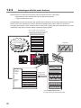
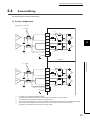
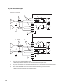
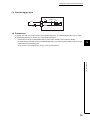
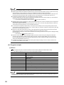
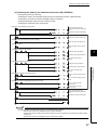
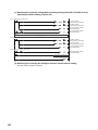
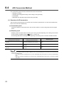
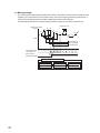
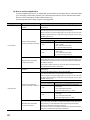
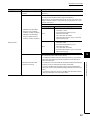
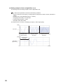
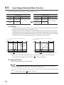
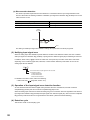
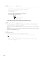
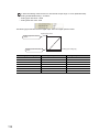
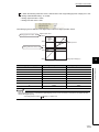
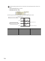
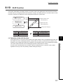
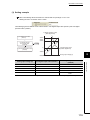
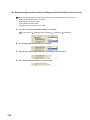
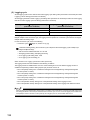
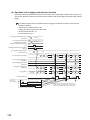
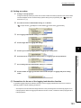
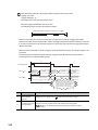
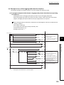
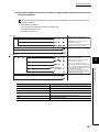
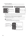
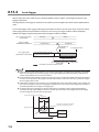
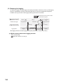
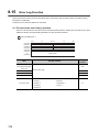
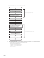
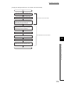
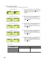
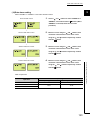
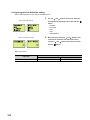
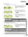
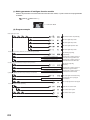
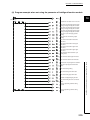
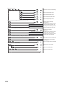
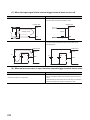
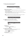
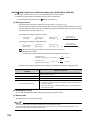
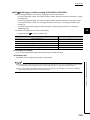
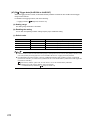
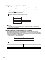
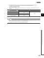
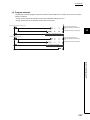
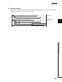
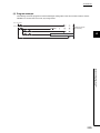
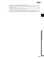
CHAPTER 6 INSTALLATION AND WIRING
6.4
External Wiring
The following figures show the external wiring.
(1) For the voltage input
Signal source -10 to 10V
*1
Shield
*2
500k
CH1
V+
CH1
I+
CH1
V-/ICH2
V+
CH2
I+
CH2
V-/I-
CH1
CH2
*3
500k
*3
500k
*2
SLD
*4
FG
6
500k
*3
Insulation
6.4 External Wiring
*1
Shield
*2
500k
CH3
V+
CH3
I+
CH3
V-/ICH4
V+
CH4
I+
CH4
V-/I-
CH3
CH4
*3
500k
500k
*3
500k
*2
SLD
*4
*1
*2
*3
*4
FG
*3
For the wire, use the shielded twisted pair cable.
In addition, keep a distance of 150mm or more from the main circuit lines or power cables.
This indicates the input resistance of the A/D converter module.
The grounds of FG between CH1 and CH2, FG between CH3 and CH4, and the internal circuit have been isolated.
Always connect the shielded wire for each channel to the shield terminal and ground the FG terminal.
In addition, ground the FG terminal of the power supply module.
53