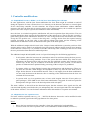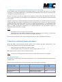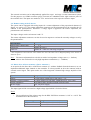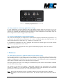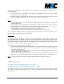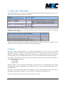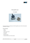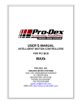
1
Description of options, upgrades and accessories
for the laser beam stabilization system
“Compact”
The basic configuration of the Compact laser beam stabilization system is fully equipped for
stabilization tasks in laser machines or laboratory set-ups. It provides all required functions and
parts (controller, detector/s, mirror holders and actuators, cables, etc.). However, for specific
installations or lasers we offer a couple of adaptations or additional modules which further help
to optimize the system for relevant parameters.
These adaptations and modules are described in this user manual. Some of these have to be
integrated in the Compact system before the delivery. Others can be ordered as additional
upgrades or accessories without the need for integration.
Contents
1. Controller modifications..............................................................................................................2
1.1. Sample&hold circuit (“ADDA“) to fix the laser beam during laser off times.................................2
1.2. Adaptation for low repetition rates..................................................................................................2
1.3. Adjustment of the proportional element (P factor) of the control loop............................................3
2. Interfaces, additional inputs and outputs.....................................................................................3
2.1. External activation...........................................................................................................................3
2.2. Remote setting of the P factors........................................................................................................4
2.3. Direct drive of Piezo actuators („Drive Actuator“).........................................................................4
2.4. Voltage offset inputs to move the target position on PSDs (“Adjust-in”).......................................5
2.5. Intensity outputs at controller (e.g. in case that UV- or vacuum-PSDs are used)............................5
2.6. Range outputs for monitoring applied Piezo voltages.....................................................................6
2.7. Set-box for adjustment of target position on PSD...........................................................................6
3. Detectors......................................................................................................................................6
3.1. Wide intensity detector: 4-quadrant diode with wide intensity range..............................................6
3.2. UV 4-quadrant diodes.....................................................................................................................7
3.3. IR 4-quadrant diodes.......................................................................................................................7
3.4. PSDs................................................................................................................................................7
4. Mirror mounts..............................................................................................................................8
4.1. Adapters for mirror dimensions of 0.5'', 1.5'' and 2''........................................................................8
4.2. Mirror mounts for 3'' and 4'' mirrors ...............................................................................................9
5. Vacuum adaptions.......................................................................................................................9
6. Optical components.....................................................................................................................9
6.1. Optical filters...................................................................................................................................9
6.2. Mirrors, lenses.................................................................................................................................9
7. Cables, other cable lengths........................................................................................................10
8. Shutter........................................................................................................................................10
9. Contact.......................................................................................................................................11
Compact beam stabilization / Options and accessories
version 4 – September 07, 2015
page 1 of 11
1. Controller modifications
1.1. Sample&hold circuit (“ADDA“) to fix the laser beam during laser off times
In some applications with the laser beam stabilization the laser beam might be switched on and off
during the operation. In laser off times there is no intensity on the detectors and hence no control signal
for the closed-loop controller. In such situations, the Compact beam stabilization without additional
measures will drive the Piezo-driven steering mirrors into a defined position, the so-called zero position
(please refer to the Compact system's user manual for more information).
Once the laser is switched on again the stabilization will start its operation from this position. The zero
position should have been used for the first adjustment of the optical set-up. That is why this is usually a
good starting point for the stabilization. However, in cases of large drifts of the laser beam in the overall
set-up, the zero position can – at least in the long term – strongly deviate from the required steering
position. Switching on the laser after a time interval without laser beam and the resuming of the
stabilization can therefore lead to an undesired initial spike of the beam position.
With the additional sample & hold circuit in the Compact beam stabilization system the positions of the
steering mirrors can be fixed for an arbitrarily long time interval without control signal or laser intensity
on the detectors. In that way it is possible to start the control-loop after switching on the laser not f rom
the zero position but from that latest stabilized position.
The additional sample & hold (S&H) circuit is of special advantage for the following applications:
–
In all systems where the laser must be switched on and off several times during the laser process,
e.g. in material processing machines. Even if the system has been drifted away from its basic
adjustment, the beam position will start from the last stabilized position after resuming of the
control loop. In this way an oscillation of the beam from the “zero position” to the desired
position is eliminated and a potential faulty processing of the work piece is prohibited.
–
In systems with a very large distance between the steering mirrors and the detectors. These set ups bear the risk that a drift changes the adjustment in that way, that the laser beam will no
longer hit the detector in uncontrolled intervals. Thus, it can happen, that the beam stabilization
can not catch the beam on the detectors after a resuming of the stabilization when the laser was
switched off for some time.
–
In systems with very low repetition rates or lasers with irregular intervals of laser pulses (or
pulse packages). If the S&H circuit of the beam stabilization is triggered for each laser pulse the
beam position will get closer to the desired position with each pulse.
The name “ADDA” is derived from the functional aspect that the actuators' drive signals are first AD
converted and digitally stored before they are subsequently DA converted again and fed to the amplifiers
of the mirror actuators. You can find more information about this module in a separate user manual.
1.2. Adaptation for low repetition rates
For lasers with low repetition rates (e.g. 10 … 300 Hz) the detector electronics can be modified in order
to maintain a position signal in the time gaps between two laser pulses.
Notes:
•
•
Due to the low repetition rate the controller is then also optimized to low bandwidths.
For lasers with even lower repetition rates we recommend our ADDA module (section 1.1).
Compact beam stabilization / Options and accessories
version 4 – September 07, 2015
page 2 of 11
1.3. Adjustment of the proportional element (P factor) of the control loop
In the standard set-up, the proportional and integral elements of the control loop lead to a very stable
performance of the beam stabilization system with desired bandwidths. That is why no user interactions
are required to adjust the control loop.
However, in specific cases the user might wish to adjust the control loop for his application. Such cases
can be set-ups with rather long arm lengths or the requirement to achieve the highest possible bandwidth
of the system.
Since the control loop is mainly affected by the proportional element, we can offer a direct access to the
proportional element by means of potentiometers at the side panel of the controller box. This can be done
separately for each stage of the system. In order to optimize the performance, we recommend to start
with a small P factor and operate the system in this stable configuration. Then you can increase the P
factor by simply turning the potentiometer in clockwise direction, until the system reaches its
stabilization limits and starts to oscillate.
Notes:
•
•
The optimal P factors of stage 1 and 2 can differ.
If the distances of the optical components, the beam diameter, the laser intensity, or other laser
data change, the P factor of the overall system might also change.
We also offer an interface for the remote setting of the P factor. This is described in section 2.2.
2. Interfaces, additional inputs and outputs
Beside the inputs for the detectors and the outputs to the actuators the basic configuration of the
Compact beam stabilization provides the following outputs:
•
•
Status signal (see user manual of Compact system)
Position signals x and y of each detector (analog voltage signal -5 to +5 V)
Other signal outputs or inputs can be provided as options.
Note: In some cases the arrangement of the connectors on the side panels have to be changed.
2.1. External activation
The external activation enables the change of the operation state of the beam stabilization system with an
external signal.
There are three operation states. The specification of the control signal is as follows:
Signal
Voltage range
(Level: 5V TTL)
H (high)
2.4 – 5.0 V
L (low)
0.0 – 0.8 V
Z (high impedance or not
connected)
Compact beam stabilization / Options and accessories
Controller status
Start
Stop
Manual mode according to
selection on front panel
version 4 – September 07, 2015
Reaction of
Active LED
on
off
on/off
page 3 of 11
The external activation can be independently applied for stage 1 and stage 2 of the stabilization system.
For this purpose, two LEMO connector plugs (series 00) are embedded on the right connector panel of
the controller box. The inputs are marked as “Ext” and are next to the respective detector inputs.
2.2. Remote setting of the P factors
The system can be equipped with analog inputs for a remote adjustment of the proportional elements (P
factors, see section 1.3). The remote adjustment connectors are then integrated into the controller box in
addition to the potentiometers. Whenever a voltage signal is applied to the remote adjustment, the
potentiometers are ineffective.
The input voltages can be set between 0 and 5 V.
The remote adjustment connectors can also be used as outputs to read out the currently voltages as set by
the potentiometers.
Specification:
Input/output voltage range:
Connector:
Cable set:
0 … +5 V
LEMO 00 series *
LEMO 00 -> BNC for each stage, length 2m
* The configuration of the connectors at the controller box and of the cables can be changed depending on the selection of
additional options.
Note: The remote adjustment has to be driven with a low impedance voltage source (<= 1kOhm),
whereas the read-out drives only high impedance terminations (>= 1 MOhm).
2.3. Direct drive of Piezo actuators („Drive Actuator“)
As an option for the direct drive of the Piezo actuators (i.e. without feedback from the detectors) we can
implement additional input channels to the controller. It is then possible to drive the actuators with an
external control signal. This option makes use of the integrated 4-channel high-voltage amplifier of the
system.
Specification:
Inputs:
Outputs / to Piezo actuator:
Output impedance:
Power supply:
Integrated 140V voltage converter
4 signal inputs (LEMO 00) on side panel, +/-5V
4 voltage outputs on side panel, LEMO 0S series, 9V to 120V
110 Ohm@1kHz, designed for high capacitive load
12V, 2A power supply
The input signal will be converted to a high-voltage signal which is fed to the Piezos.
Notes:
•
The specification of the voltage range for the PKS / PSH Piezo actuators is -20V to +130V. The
maximum tilt for the actuators is
Actuator type
PKS
PSH
Compact beam stabilization / Options and accessories
Range
> 1 mrad (0.5 mrad in each direction)
> 2 mrad (1.0 mrad in each direction)
version 4 – September 07, 2015
page 4 of 11
We have specified the voltages to values of 9V to 120V for the valid range of the green range
LEDs (max. range 0-130V).
•
There is a non-linearity in both, the characteristics of the Piezos and the amplifiers. Therefore the
signal will not be fully proportional to the input signal. If you need a precise and absolute
position of the steering mirrors (without the control-loop which usually gives the position
feedback) you should carry out a calibration of the angles versus voltages.
•
It is also possible that the x and y axes of the same Piezo actuator vary strongly.
2.4. Voltage offset inputs to move the target position on PSDs (“Adjust-in”)
As described in section 3.4 the measurement principle of PSDs allows to move the target position on the
detector by means of a voltage offset. For this purpose we can implement additional inputs for the x and
y axes of both, stage 1 and stage 2. These inputs can be used to change the still stabilized beam position
by an external source. The input voltage range of these inputs is -5V … +5V.
Figure 1: Left panel with four additional “Adj-in” inputs for
x and y position of two PSDs
Figure 1 shows the modified side panel of the controller box with additional “Adj-in” inputs for the
voltage offset.
Note: The position vs. voltage characteristics of a PSD is usually not linear. Therefore, a calibration
should be performed if the target shall be moved on a desired path.
2.5. Intensity outputs at controller (e.g. in case that UV- or vacuum-PSDs are used)
Since the UV- and vacuum-versions of the PSD detectors do not have the intensity level displays we can
add additional intensity voltage outputs at the controller box. Figure 2 shows these outputs marked with
“Int” close to the detector inputs. In this figure, the standard 4QD input connectors are labelled as input
connectors for PSDs.
Compact beam stabilization / Options and accessories
version 4 – September 07, 2015
page 5 of 11
Figure 2: Right panel with PSD input connectors and
intensity output connectors
2.6. Range outputs for monitoring applied Piezo voltages
In some applications it can be helpful to know the applied voltage ranges of the Piezos, e.g. to see
whether or not the tilting range of the Piezos (and therefore the voltage range) is at its limits. If the Piezo
actuators are combined with additional motorized mounts in order to enlarge the overall tilting range, the
Piezo voltage can be used as a trigger to drive the motors.
2.7. Set-box for adjustment of target position on PSD
The set-box was developed as a simple tool for demonstration purposes and laboratory applications. It is
an electronic box which offers potentiometers for x and y to manually adjust the target positions and
outputs to the Piezo driver electronics (e.g. “Adjust In”, see section 2.4).
In an additional configuration it can be equipped with inputs for external signals so that an external
signal from a signal generator can be added.
Note: The box can be equipped with x and y position and intensity displays. Please also ask for
appropriate cables.
3. Detectors
3.1. Wide intensity detector: 4-quadrant diode with wide intensity range
In some applications the laser intensity is varied or modulated over wide ranges. The performance of the
wide intensity detector is fully independent of the intensity. The signal amplification automatically
adapts to changing powers. The power can vary by a factor of >1,000 without the need of exchanging the
optical filters. External signals or user interactions are not required.
Since the signal-to-noise ratio is not changed, the stabilization system reaches the maximum resolution
over the entire intensity range.
The function of the power level display is unchanged compared to the description in the Compact
system's user manual, i.e. it can still be used to support the selection of the optical filters. In contrast, the
potentiometer as described in section 4.5. of the user manual is omitted.
Note: Due to the wide intensity range it is possible to detect even lowest laser powers. Therefore,
depending on the selection of the optical filters, the detection signal can be affected by ambient
light.
Compact beam stabilization / Options and accessories
version 4 – September 07, 2015
page 6 of 11
3.2. UV 4-quadrant diodes
For lasers with UV wavelengths we offer two 4-quadrant-diodes with different sensitive areas and the
following specs:
Specification:
Wavelength range:
Sensitive area:
UV 4-quadrant diode – Type 1
190-1,000 nm
3x3 mm2
UV 4-quadrant diode – Type 2
5-1,000 nm
10x10 mm2
Figure 3 shows a photo of the sensor side of the Type 1 UV 4QD.
Figure 3: UV 4-quadrant diode with sensitive area of 3x3 mm2
3.3. IR 4-quadrant diodes
For laser with infrared wavelengths we offer a 4-quadrant diode with the following specs:
Specification:
Wavelength range:
Sensitive area:
IR 4-quadrant diode (Germanium)
800-1,800 nm
Ø = 5 mm
Note: We also offer a 4-quadrant detector for CO2 lasers at 10.6 µm. Such lasers are often operated
with powers in the range of several kW and large and heavy-weight mirrors. That is why the
integration of the stabilization system can require additional measures for mounting the actuators
and leaking a portion of the laser power to the detectors.
3.4. PSDs
As an alternative to our standard 4-quadrant diodes we offer PSDs (position sensitive device) for visible
and for UV wavelengths with the following specs:
Specification:
Wavelength range:
Sensitive area:
VIS PSD
400-1,100 nm
9x9 mm2
Compact beam stabilization / Options and accessories
UV PSD
200-1,100 nm
10x10 mm2
version 4 – September 07, 2015
page 7 of 11
Compared to the 4-quadrant diodes the PSDs have a continuous measurement area. This leads to two
possible advantages:
1) The sensitive area is not divided by a gap. Therefore, the PSD can be used in case of very small
beam diameters or focused beams.
2) Whereas with the 4-quadrant diodes the target point is usually defined by their cent re, in case of
the PSDs any other point on the sensitive area can be chosen as a target point.
Notes:
•
•
•
•
The UV-PSDs do not have the position and intensity displays at the housing as the standard 4quadrant diodes have.
If we equip the beam stabilization with PSDs but no further measures, we use the electronic
center (defined by a voltage of 0V for x and y position) as the target position.
The position vs. voltage characteristics of a PSD is usually not linear. Therefore, a calibration
should be performed if the target shall be moved on a desired path.
The UV PSD can not be used for pulsed lasers with repetition rates below 1 kHz.
Please consider the additional input and output options of sections 2.4 and 2.5 which can further improve
the functionality of stabilization systems with PSDs.
Applications:
If you use the PSDs instead of 4-quadrant diodes, the position detection is not limited to the centre as it is
with 4-quadrant diodes. By adding a voltage to the signal of the PSD the target position where the laser
beam shall hit the PSD can be moved. Still, the beam stabilization will provide full stabilization of the
beam direction, but the direction itself can be manipulated. The external signal can be applied to the
system via the “Adjust in” functionality described in section 2.4.
This feature can be used for different applications, e.g.:
•
Place the PSDs before the laser is finally adjusted. Then adjust the laser and read-out the target
position. Feed back the voltage for the new target position. The system will then stabilize the
laser beam onto this position.
•
Place the PSDs before the laser is finally adjusted. Then move the position on the detectors until
you have the optimal laser adjustment.
•
Move the laser beam to different points (or along a pattern) by moving the beam position on the
PSDs. You can vary the laser beam direction with highest resolution and it is still stabilized.
Note: A simple tool to move the target position by potentiometers is shown in section 2.7.
4. Mirror mounts
4.1. Adapters for mirror dimensions of 0.5'', 1.5'' and 2''
Our standard mirror mounts PKS and PSH have holders for 1'' mirrors.
The PKS mirror mount is also available with a holder for 0.5'' mirrors. The PSH mount can be combined
with adapters for larger mirror dimensions of 1.5'' and 2''. The left photo in figure 4 shows the mount
with a 2'' mirror.
Compact beam stabilization / Options and accessories
version 4 – September 07, 2015
page 8 of 11
4.2. Mirror mounts for 3'' and 4'' mirrors
Our beam stabilization systems can also drive mirrors with larger dimensions. The right photo in figure 4
shows an example. Please be aware that the bandwidths which can be achieved with such mirrors is
lower than with standard components.
Figure 4: PSH mirror mount with a 2'' mirror held by an adapter (left) and 4'' mirror actuator (right)
5. Vacuum adaptions
Both, the detectors and the actuators can be adapted for use in vacuum. In case of the actuators, this is
possible for vacuum pressures down to 10-11 mbar. But this is an extreme value. In case you intend to
place some components in vacuum please let us know the conditions so that we can discuss and offer the
required measures with you. Some measures (choice of materials and cables, sealing) are mainly
focussed to avoid degassing and depend on the pressure. Other measures are important to protect the
components themselves.
Note: The controller itself should not be placed in vacuum.
6. Optical components
6.1. Optical filters
We usually offer to integrate a pair of optical filters in front of each sensor. The filters have a size of
11.9x11.9 mm2 and fit into the provided slot in the detector housing.
6.2. Mirrors, lenses
We can also offer appropriate filters or lenses for your set-up. However, since we do not produce optical
components by our own we do not have any price advantages compared to our customers.
Compact beam stabilization / Options and accessories
version 4 – September 07, 2015
page 9 of 11
7. Cables, other cable lengths
The standard delivery of a Compact laser beam stabilization system includes all required cables to set up
the system and to read out the positions. These are:
Cable set
(included in standard delivery)
Detector → Controller
Actuator → Controller
Actuator → Controller (Elongation)
x-y-position cable (Lemo → BNC)
quantity length
2
2
4 m (including the 3xMXC/power → Lemo adapter cable)
PKS: 1.5 m (directly mounted to Piezo element)
PSH: 1.2 m (directly mounted to Piezo element)
1 pair for 10m
1 actuator
2
2m
In addition to these cables we can also offer additional cables or cables with other lengths. The following
table shows some examples.
Other available cables and/or lengths (examples)
Elongation cables for 4QD detectors (Lemo → Lemo)
Elongation cables for actuators (Lemo → Lemo)
Cables for external activation (Lemo → BNC)
Cables to connect the intensity ouput (Lemo → BNC)
Typical lengths
1 m … 25 m
1 m … 25 m
2m
2m
If you do not find the cable you need please do not hesitate to contact us. Since we assemble various
cables in-house we can customize almost any cable and cable length.
8. Shutter
The laser shutter system Beamblock was especially developed for the use with our laser beam
stabilization systems. It fulfils the safety function to block the laser beam in such cases where the
stabilization system isn´t capable to align the laser beam due to exceeding beam deviations. For this task
the status signal “OK” of the stabilization system is used to control the laser shutter system externally.
The shutter system consists of a laser shutter and a shutter controller that allows to drive the shutter in
three different modes of operation:
•
confirm mode
•
external mode
•
manual mode
Thus the shutter can be controlled automatically by other devices or semi-manually with a safety
confirmation by the user. Additionally it is possible for the user to open and close the shutter directly in
the manual mode.
The input for external signals is prepared for standard TTL-levels, which allows the shutter system to be
compatible to most other controllers (e.g. laser interlock or computer controlled devices).
Figure 5 shows photos of the laser shutter and the shutter controller.
Compact beam stabilization / Options and accessories
version 4 – September 07, 2015
page 10 of 11
Laser beam
Figure 5: Laser shutter (left) and shutter controller (right)
You can find more information about this module in a separate user manual.
9. Contact
MRC Systems GmbH
Hans-Bunte-Str. 10
D-69123 Heidelberg
Germany
Phone:
Fax:
Website:
E-mail:
+49-(0)6221/13803-00
+49-(0)6221/13803-01
www.mrc-systems.de
[email protected]
Compact beam stabilization / Options and accessories
version 4 – September 07, 2015
page 11 of 11