1
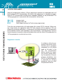
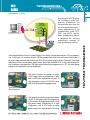
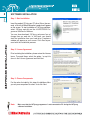
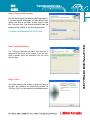
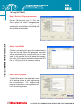
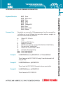
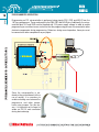
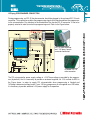
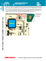
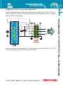
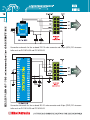
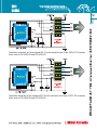
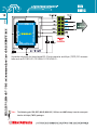
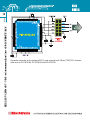
CONTENTS
18FJprog Programmer
Software Installation
18FJprog Software
Keyboard Shortcuts and Command Line Parameters
Programmer’s Operation
18FJprog Programmer Connection
Examples of the PIC Microcontroller Connection
4
6
8
9
10
11
13
4
18FJPROG PROGRAMMER
Along with complementary software, 18FJprog programmer represents an irreplaceable tool for all
those working with PIC microcontrollers. By means of this programmer, it is possible to program
almost all PIC microcontrollers including those embedded (soldered) on the printed board. The
18FJprog programmer is connected to the microcontroller via three lines:
18FJPROG PROGRAMMER
RB6 - PGC
RB7 - PGD
MCLR
(program clock);
(program data); and
(high voltage necessary for Flash memory programming).
These lines are contained within a flat cable ending with a female IDC-10 connector. When creating a target device, the appropriate 10-pin IDC male connector with the spacing of 2.54 mm
between pins should be soldered on it. Connector pins should be connected to the microcontroller
pins the position of which varies depending on the microcontroller’s type and package. There are
several examples of connection schematic provided at the end of this manual. During operation, the
18FJprog programmer may be inactive or active.
Programmer is inactive
A multiplexer within the programmer connects the microcontroller pins to peripheral
components on the printed
board via flat cable. In this
way, the microcontroller
directly controls the operation of device without affecting the operation of the programmer. Accordingly, even
the IDC-10 female connector
is connected, the 18FJprog
programmer does not affect
the operation of device.
5
Programmer is active
If the target board has its own 5V power supply, it can also be used for powering the 18FJprog programmer. In this case, it is necessary to open 18FJprog programmer plastic case and remove the jumper J1
for power supply selection and place jumper J2 on 5V as shown on figures below. Otherwise, if the target
board does not have its own power supply source, the jumper should be left on. In this case the programmer is powered via programmer USB cable which connects the programmer to a PC. Any other power
supply on the target board must be suspended.
This figure illustrates the position of jumper
J1(left image) when the programmer is powered via USB cable. And position of jumper J2
(right image)when is set to 3.3V if MCU is powered from 18FJprog during programming.
Default position
This figure illustrates the programmer without
jumper J1 (left image) when the programmer
is powered by the target board which has its
own power supply. And position of J2 (right
image)when is set to 5V in order to enable
power supply from target board to 18FJprog.
18FJPROG PROGRAMMER
By clicking the WRITE option,
the multiplexer within programmer disconnects the
microcontroller pins from the
rest of on-board electronics. It
allows programming of the
microcontroller using PGC,
PGD and MCLR signals.
When programming process
is completed, the 18FJprog
automatically changes its
state and becomes inactive.
6
SOFTWARE INSTALLATION
Step 1: Start installation
SOFTWARE INSTALLATION
Insert the product CD into your PC drive. After a few seconds, a list with all MikroElektronika’s products will appear
on the screen. To start installation of 18FJprog software,
select 18FJprog and click on the Lv18PICFLASH Programmer Software for Windows.
You can also download 18FJprog_setup.exe free of
charge from our web site. In this case, you should
start the installation from your hard drive. A welcome
window will appear on your screen. Click Next to proceed with the installation process.
Step 2: License Agreement
Prior to starting the installation, please review the License
terms. To accept these, select the option I accept the
terms in the License Agreement and click Next.
Step 3: Choose Components
For the sake of simplicity, this step of installation offers
you only one component to select. Just click Next.
Note:
Make sure that the 18FJprog programmer is not connected to PC during the 18FJprog
software installation.
Step 4: Choose Install Location
7
Now you should specify the folder to install the program in.
If you want to install the program in a folder different from
default, click Browse and select another folder on hard
disc. Then click Next. If you choose the default folder, the
program will be installed on the following destination:
Step 5: Installation Details
The 18FJprog installation will start in this step and its
progress will be shown on the screen. If you are interested in details about the installation click the Show
details button.
Step 6: Finish
You will be notified by the window, as shown in Figure on
the right, that Windows has successfully installed the
18FJprog. Click Finish to complete the installation process.
SOFTWARE INSTALLATION
C:\Program Files\Mikroelektronika\lv18PICFLASH
8
18FJprog SOFTWARE
Step 1: Run the 18FJprog programmer
18FJPROG SOFTWARE
Run the 18FJprog from your PC. Click the
Device option and select the appropriate
microcontroller to program. 18FJprog will
automatically set parameters for working with
the specified microcontroller.
Step 2: Load HEX file
Click the Load option which opens the window shown in
Figure on the right. Select the appropriate executable
file (has extension .HEX in its name) and click the Open
option. In this way, the file will be loaded into programmer buffer. On the basis of control bits stored in the HEX
file, the 18FJprog will do all necessary settings.
Step 3: Write a program
Click the Write option in the upper right corner
of the working window to start programming
the microcontroller. The programming
progress will be shown in the right bottom corner of the working window.
Keyboard Shortcuts
Command Line
Alt-E
Alt-B
Alt-W
Alt-V
Alt-R
Alt-D
Ctrl-S
Ctrl-O
Ctrl-R
Alternatively, you can use the 18FJprog programmer from the command line.
It will allow you to use 18FJprog from some other software, compiler etc.
Here are the command line parameters:
-w
-v
-r
-e
-p
-f
-b
-Q
-Uon
-Uoff
Example 1
Erase
Blank check
Write
Verify
Read
Change MCU
Save
Open (Load)
Reload
Write to PIC 18FxxJxx
Verify
Read from PIC 18FxxJxx
Erase PIC 18FxxJxx
PIC18FxxJxx name (for example PIC18F67J10, PIC18F97J60...)
File name (use " as delimiters)
Check if PIC 18FxxJxx flash is blank
Terminate after programming
Force Code protection
Force Code unprotect
Lv18PICFLASH.exe -w -pPIC18F67J10 -v -f"C:\somefile.hex"
This will program the PIC P18F67J10 using C:\somefile.hex and it will
verify the write.
Example 2
Lv18PICFLASH.exe -r -pPIC18F67J10.
This will read the PIC P18F67J10 contents into on screen buffer.
Example 3
Lv18PICFLASH.exe -e -pPIC18F67J10
This will erase the PIC P18F67J10.
9
KEYBOARD SHORTCUTS AND COMMAND LINE PARAMETERS
KEYBOARD SHORTCUTS AND COMMAND LINE PARAMETERS
10
PROGRAMMER’S OPERATION
P ROGRAMMER’S OPERATION
Programming an PIC microcontroller is performed using signals PGC, PGD and MCLR from the
18FJprog programmer. These are brought to the RB6, RB7 and MCLR pins. Additionally, the microcontroller pins VCC and GND must be supplied with 3.3V power supply voltage. In order to enable
programming to run without errors, make sure that the programming pins are not connected to other
electronic components during programming. Otherwise, during normal operation, these pins must
be connected to other components as per project.
Since the microcontroller is soldered on the printed board (with no
use of socket), it is necessary to
enable switching over between the
programmer and other components using jumpers. For this reason, it is important not to forget to
solder an IDC-10 male connector
during device design.
11
18FJprog PROGRAMMER CONNECTION
IDC-10 male connector
and 18FJprog female
connector connected
On-board IDC-10
male connector
The PIC microcontroller power supply voltage is +3.3V.These voltage is provided by the programmer (by default). And it is necessary to provide an on-board regulator, for 3.3V, marked as REG in
the Figure above, in order to supply PIC microcontroller when programming is finished and
18FJprog is disconnected from board. If your 18FJprog programmer is not supplied over USB cable,
it is necessary to provide additional +5V power supply for its operation.
18FJPROG PROGRAMMER CONNECTION
During programming, an IDC-10 female connector should be plugged in the on-board IDC-10 male
connector. This connection enables the programming signals to be transferred from the programmer
to the microcontroller. Pay attention to the orientation of the female IDC-10 connector. It has to be
properly oriented in order to make this programming work. Refer to the Figure below.
12
During normal operation, on-board IDC-10 pins must be connected using jumpers as shown in Figure
below. In this way, the microcontroller pins are connected to the rest of on-board electronics. Note that
RB6, RB7, MCLR and GND pairs of pins of the IDC-10 male connector are connected using jumpers. You
must not connect first pair of pins, which are used for power supply (MCU-VCC +3.3V and VCC +5V)
because it can make a short circuit connection and it's possible to damage your device.
18FJPROG PROGRAMMER CONNECTION
On-board IDC-10
male connector
with jumpers.
EXAMPLES OF THE PIC microcontroller CONNECTION
13
Connection schematic for the on-board IDC-10 male connector and 28-pin (SPDIP, SOIC, SSOP)
PIC microcontroller such as PIC18F24J10 and PIC18F25J10.
EXAMPLES OF PIC microcontroller CONNECTION
The following examples illustrates the connection between 28 (SPDIP, SOIC, SSOP); 28 (QFN); 40
(PDIP); 44 (QFN); 44 (TQFP); 64 (TQFP); 80(TQFP) and 100 (TQFP) pins PIC18FxxJxx microcontroller and IDC-10 male connector.
EXAMPLES OF PIC microcontroller CONNECTION
14
Connection schematic for the on-board IDC-10 male connector and 28-pin (QFN) PIC microcontroller such as PIC18F24J10 and PIC18F25J10.
Connection schematic for the on-board IDC-10 male connector and 40-pin (PDIP) PIC microcontroller such as PIC18F44J10 and PIC18F45J10.
Connection schematic for the on-board IDC-10 male connector and 44-pin (QFN) PIC microcontroller such as PIC18F44J10 and PIC18F45J10.
Connection schematic for the on-board IDC-10 male connector and 44-pin (TQFP) PIC microcontroller such as PIC18F44J10 and PIC18F45J10.
EXAMPLES OF PIC microcontroller CONNECTION
15
EXAMPLES OF PIC microcontroller CONNECTION
16
Connection schematic for the on-board IDC-10 male connector and 64-pin (TQFP) PIC microcontroller such as PIC18F63J11, PIC18F64J11, PIC18F65J11...
Note: The following pins RB6, RB7, MCLR, MCU-VCC, VCCcore and GND always have the same position for all 64-pin (TQFP) packages.
Connection schematic for the on-board IDC-10 male connector and 80-pin (TQFP) PIC microcontroller such as PIC18F83J11, PIC18F84J11, PIC18F85J11...
Note: The following pins RB6, RB7, MCLR, MCU-VCC, VCCcore and GND always have the same position for all 80-pin (TQFP) packages.
EXAMPLES OF PIC microcontroller CONNECTION
17
EXAMPLES OF PIC microcontroller CONNECTION
18
Connection schematic for the on-board IDC-10 male connector and 100-pin (TQFP) PIC microcontroller such as PIC18F96J60, PIC18F96J65 and PIC18F97J60.