1
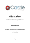
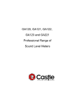
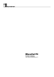
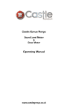
CASTLE GROUP
USER MANUAL FOR
ACOUSTIC CALIBRATORS:
GA601 and 607
COMPANY INTRODUCTION
Thank you for buying a Castle product, we are sure you will find both the goods and the
service to be of the highest quality but if not, then please feel free to contact us so that we
can deal with any concerns you may have.
This manual is designed to show you the operation of the goods you have purchased. If you
would like to become a competent person in the eyes of the law, then you may like to know
more about our competent person training courses for the Noise at work regulations or
Environmental noise assessments.
It is our aim at Castle Group Ltd to provide a complete range of Noise and Vibration
products and Services of the highest standard. If you would like to know more about any of
our other products and services then please telephone on:
+44(0) 1723 584250 or visit our Website at www.castlegroup.co.uk.
Simon Bull MIOA
Managing Director
1
CONTENTS
SECTION
PAGE NUMBER
INTRODUCTION
3
BATTERY CHECK AND REPLACEMENT
4
OPERATION
5
CORRECTION FACTORS
6
GA690 ELECTRONIC BAROMETER
8
SPECIFICATIONS
11
WARRANTY AND AFTER SALES SERVICE
13
2
INTRODUCTION
When using any type of sound level meter it is highly recommended that the equipment is
acoustically calibrated before and checked again after measurements are made.
The GA601/GA607 acoustic calibrators provide an accurate, stable and simple to use
sound source for carrying out the acoustic calibration of a wide range of sound level
meters. Both calibrators operate at 1kHz and thereby eliminate possible confusion
regarding the frequency weighting selected on the Sound Level Meter (since A,B,C and D
weightings all have unity gain at this frequency). Both calibrators feature non-latching toggle
switch operation which engages the sound source for a continuous period of one minute
before automatically turning off. The GA601 is a Class 2/C acoustic calibrator that
produces a 94dB stable tone and the GA607 is a Class 1/C acoustic calibrator that
produces both 94dB and 104dB tones.
Rugged, reliable and economic operation of the GA601/607 has been ensured by the use
of a high-tech integrated circuit, a metal cone transducer, positive battery condition
indication and readily available batteries. Their compact size and light weight permit
convenient pocket carrying and hand-held calibration of instruments.
The GA601/607 calibrators are designed for use with Castle sound level meters as well
as a variety of third party sound level meters that feature a nominal half inch microphone
capsule.
3
BATTERY CHECK AND REPLACEMENT
The battery condition of the GA601/607 is continuously indicated when the instrument is
switched on, by means of a bright red LED (light emitting diode). If the LED does not
illuminate when the unit is switched on then the batteries in the unit need replacing and
levels output by the calibrator may fall outside the published tolerance limits.
The procedure for replacing the batteries is as follows:1
Pull off the black retainer ring surrounding the switch panel by pulling with a slight
twist. If necessary use a screwdriver through the two holes in the ring to pull it off.
The retainer is held in place by a rubber ‘o-ring’ and a fairly firm ‘pull and twist’ is
required to remove it.
2
Remove the metal plate carrying the switch and PCB by pulling on the switch.
Continue pulling gently until the entire PCB is outside the bodytube taking care not to
pull too far or the wires connecting it to the transducer may break. - see figure 1
3
Unclip the lithium batteries from their holders by carefully prising them out from
under their clips.
4
Insert the new batteries under the holder clip with the positive to the top (the holder clip
may require pushing back down to make good contact on the battery before you put the new batteries
in).
5
Insert the switch panel/PCB assembly back into the bodytube and fit the black
retainer ring on top by pushing firmly until flush with the bodytube.
6
Turn on the GA601/607 and verify that the LED is illuminated.
Figure 1
4
OPERATION
The Castle GA601 and GA607 acoustic calibrators feature non-latching toggle switches.
The toggle switches turn the unit on. The units will automatically turn off one minute after
the last operation of the toggle switch (it is not possible to turn the unit off manually. To ensure an
accurate calibration please ensure that the ambient noise level is at least 20dB lower than
the chosen level of the calibrator e.g. 74dB if using a 94dB level. This check can be carried
out with the Sound Level Meter prior to the calibration.
The following routine outlines a basic calibration check on a sound level meter using a
Castle GA601/607 acoustic calibrator (please refer to the sound level meter user manual for more
specific information on carrying out a calibration check):
1
Check the battery condition of both the Sound Level Meter and the GA601/607 and
replace if necessary.
2
Ensure the calibrator is attached to the microphone correctly by gently inserting the
microphone into the cavity of the calibrator (the cavity can be found on the opposite end of the
unit to the toggle switch). A certain amount of resistance should be felt whilst inserting
the microphone as the o-ring fitted to the cavity of the calibrator forms a seal around
the microphone – see figure 2
3
Refer to the sound level meter user manual for information on setting the instrument
ready for calibration.
4
Ensure that the calibrator is switched on and set to the chosen level and all
correction factors for atmospheric pressure and microphone type have been
accounted for.
5
Allow both units to settle for approximately 5 seconds before calibrating.
Figure 2
5
CORRECTION FACTORS
Sound Pressure correction:
The nominal sound pressure level within the calibrator cavity varies from one microphone
type to another. Refer to Table 1 for the pressure to free field correction factor to be applied
to the actual pressure level of the calibrator to obtain the correct free field reading with the
microphone you are using:
Microphone Type
MK75 (ACO 7146)
MK78 (MTG. MK250)
MK79 (ACO 7052)
MK80 (ACO 7146A)
BK4133 (WS2 approved)
Correction factor to be applied
-0.3dB
-0.2dB
-0.2dB
-0.3dB
-0.2dB
Table 1
Atmospheric Pressure correction:
Variations in atmospheric pressure both at altitude and at sea level can affect the
calibration level. The graph in figure 3 highlights the correction factor to be applied when
using Class 1 accuracy equipment depending on the atmospheric pressure at the time of
calibration. The same factor can also be applied when using Class 2 accuracy equipment
although this is optional. The Castle GA690 electronic barometer is recommended for
accurately obtaining the atmospheric pressure.
Pressure Correction Level (dB)
Calibrator Pressure Corre ction Graph
0.3
0.2
0.1
0
-0.1
-0.2
-0.3
-0.4
-0.5
-0.6
-0.7
-0.8
-0.9
-1
-1.1
-1.2
-1.3
-1.4
-1.5
-1.6
-1.7
650
700
750
800
850
900
950
1000
1050
1100
Pressure (mbar)
* The expanded uncertainty of measurement associated with the correction data for atmospheric pressure
is ±0.03dB
figure 3
6
Altitude correction:
When barometric pressure figures are published on weather forecasts the figure quoted
will usually have been adjusted down to sea level. This means that the pressure will be
different in your location to the published figure depending on the altitude of your location. If
you intend to use this published figure, the following corrections need to be applied:
An approximation for small height differences (<1000m) can be obtained by reducing the
barometric pressure by 0.116mbar/metre increase in height above sea level.
For greater heights please refer to Table 2 for barometric pressure adjustment
Altitude (0m = sea level)
-250m
-100m
-50m
0m
50m
100m
250m
500m
750m
1000m
2500m
5000m
7500m
Pressure Adjustment
+30.0 mbar
+12 mbar
+6 mbar
0 mbar
-6 mbar
-12 mbar
-29 mbar
-58 mbar
-87 mbar
-114 mbar
-266 mbar
-473 mbar
-630 mbar
Table 2
Please note that the Castle GA690 electronic barometer measures the absolute pressure
at your location. When using the GA690 no correction for altitude needs to be applied.
Example 1 (Without Using Castle GA690):
You want to calibrate a GA215 sound level meter which features an MK79 (ACO.7052) microphone
using a GA601 calibrator with a weather station pressure reading of 960 mbar. You are located 500m
above sea level. To find the level you should be calibrating to you need to take the following stages into
account:
Actual pressure level of the calibrator:
Microphone correction (-0.2dB):
93.9dB
93.7dB
Pressure correction (960 mbar)
less altitude correction (-58 mbar) = 902 mbar
902 mbar (-0.4dB):
93.3dB
Therefore the actual level that the calibrator will be outputting under these conditions is 93.3dB so this is
the level that you should set the instrument to for calibration.
Example 2 (Using Castle GA690):
Obtain the barometric pressure using the Castle GA690 and use figure3 to obtain the correction factor.
The example below is for a GA690 reading of 1040mbar using a GA131M sound level meter which
features an MK78 (MK250) microphone and a GA607 calibrator to calibrate the instrument.
Actual pressure level of the calibrator:
Microphone correction (-0.2dB):
Pressure correction (1040 mbar)
94.1dB
93.9dB
0.1dB
Therefore the actual level that the calibrator will be outputting under these conditions is 94.0dB so this is
the level that you should set the instrument to for calibration.
7
GA690 Electronic Barometer (where supplied)
The Castle GA690 electronic barometer can be used with both the GA601 and GA607 to
accurately display the atmospheric pressure at your location.
The barometer measures the absolute pressure of the ambient atmosphere. The pressure
measured is not necessarily the same pressure as would be published on weather
forecasts etc as this figure is normally the pressure taken at sea level. The barometer can
be set to display the figure at sea level by using the S.L (sea level correction) function if your
altitude is known.
Powering the barometer on:
To turn the barometer on simply press and release the ON/OFF key once. The barometer
should then turn on and perform a segment test on the display. To turn the barometer off
simply press and release the ON/OFF key once more.
Configuration of the barometer:
1. Auto power off (P.of) - It is possible to set the barometer to automatically turn off after
a preset time off between 1 and 120 minutes:
I.
II.
III.
Press and hold the MODE key whilst powering on until ‘P.of’ is displayed
Press the MODE and ZERO keys to scroll up and down in minutes to select your
desired power off time. It is also possible to have the barometer to stay
permanently on by scroll down using the MODE key until ‘off’ is displayed. This
disables the auto power off function.
Confirm your selection by pressing the ON/OFF key, ‘uni’ should then appear on
the display.
2. Display unit (uni) – It is possible to change the units that the barometer displays in
between hectoPascal (hPA) and mmHg (nHg). Please note that 1hPA = 1mbar.
I.
II.
III.
Follow instructions for auto power off above.
Press the MODE and Zero keys to scroll between ‘hPA’ and ‘nHg’.
Confirm your selection by pressing the ON/OFF key, ‘S.L’ should then appear on
the display.
3. Sea level correction (S.L)* – It is possible to correct the measured pressure back to
the pressure value at sea level (zero altitude).
I.
II.
III.
Follow instructions for display units above.
Press the MODE and ZERO keys to turn the sea level correction function ‘on’ or
‘off’.
Confirm your selection by pressing the ON/OFF key. ‘Alt’ should then appear on
the display if ‘on’ was selected or the barometer will restart with if ‘off’ is
selected.
*Please note that this feature should be turned off when used for the calibration of a sound level meter
4. Altitude reading (Alt)* – If using the sea level correction function then you must set
your altitude level in metres. It is possible to enter an altitude of between 1m and
1999m.
8
I.
II.
III.
Follow instructions for sea level correction above.
Press the MODE and ZERO keys to scroll up and down in metres to select your
current altitude.
Confirm your selection by pressing the ON/OFF key, The barometer should now
restart.
Please note that if during the configuration no key is pressed within 20 seconds then the
configuration will be aborted.
*Please note that this feature should be turned off when used for the calibration of a sound level meter
Offset and Scale Adjustment:
The offset and scale adjustment function on the barometer is used for calibrating the
barometer and therefore should only be altered under calibration conditions. The following
outlines how to adjust the offset:
The display value is given by the following formula:
DISPLAY = (measured value – offset) * (1+ scale adjustment (%))
I.
II.
III.
IV.
V.
Press and hold the MODE key whilst powering on until ‘OFS’ is displayed.
Press the MODE and ZERO keys to select the required offset (-20 to +20 mbar).
Confirm your selection by pressing the ON/OFF key, ‘SCL’ should then appear on
the display.
Press the MODE and ZERO keys to select the required scale adjustment (-1.99 to
+1.99%)
Confirm your selection by pressing the ON/OFF key. The barometer should now
restart.
Please note that if during the adjustment no key is pressed within 20 seconds then the
adjustment will be aborted.
Zero Function:
The zero function is used to take relative measurements.
I.
II.
III.
Turn on the barometer.
Press and hold the ZERO key until ‘nuL’ is displayed. The display should then change
to ‘0’. As the pressure changes this figure will either increase or decrease
depending on whether the pressure is rising or falling.
Press and hold the ZERO key again to return to absolute pressure.
9
MIN/MAX Value Memory:
The barometer keeps a record of the minimum and the maximum pressures measured
whilst the barometer is turned on (values are not retained after the barometer has been
turned off).
I.
II.
III.
IV.
Ensure barometer is already turned on.
Press and release the MODE key once. The display will now flash between ‘Lo’ and
the minimum level recorded.
Press and release the MODE key a second time and the display will now flash
between ‘Hi’ and the maximum level recorded.
Press and release the MODE key a third time to return to absolute pressure.
Please note that the MIN/MAX readings can be reset by pressing and holding the MODE
key for more than 2 seconds.
Low Battery warning:
If the word ‘BAT’ appears on the screen at any time this indicates that the battery is low
and needs replacing. The barometer uses a 9v alkaline battery type 6LR61 (PP3).
10
SPECIFICATIONS
Standards:
GA601
IEC 60942:2003 Class 2/C
BS EN 60942:2003 Class 2/C
GA607
IEC 60942:2003 Class 1/C
BS EN 60942:2003 Class 1/C
The range of environmental conditions over which the calibrators are specified to
operate are:
GA601:
Air temperature:
Static Pressure:
Relative Humidity:
0°C to +40°C
65kPa to 108kPa (650 to 1080 mbar)
25% to 90%
GA607:
Air temperature:
Static Pressure:
Relative Humidity:
-10°C to +50°C
65kPa to 108kPa (650 to 1080 mbar)
25% to 90%
The reference environmental conditions for specifying the performance of both
calibrators are:
Air temperature:
Static pressure:
Relative humidity:
23°C
101,325kPa
50%
Nominal sound pressure level(s):
GA601
GA607
94dB ±0.3dB
94dB*, 104dB ±0.3dB
*Principal sound pressure level
Principal Frequency: 1 kHz ±1%
Harmonic Distortion: <3%
Stabilising time: 5 seconds
The pressure correction formula (see figure 3 on page 6):
Corrected level = -5.84448 + (7.91872E-02*p) - (2.12112E-04*p2)
(Where p is the measured atmospheric pressure in kPa)
11
EC Declaration of Conformity:
Castle Group Ltd declares that:
•
GA601/ GA607 Acoustic Calibrators
In accordance with the following Directive:
•
89/336/EEC The Electromagnetic Compatibility Directive
and its amending directives
have been designed and manufactured to the following specification:
•
EN61326-1:1997 + A1:1998
with the following Tests:
•
Radiated Emissions: EN55022:1995 Class: B
•
ESD: EN61000-4-2:1995 Levels: ±4kV (C) , ± 8kV (A)
•
Radio-frequency EM field amplitude mod: EN61000-4-3:1996 Level: 3V/m
All tests were carried out with the units in both vertical and horizontal orientations and the
differences recorded were negligible. The units were tested at all operational levels and
again the difference recorded was negligible.
We hereby declare that the equipment named above has been designed to comply with the
relevant sections of the above referenced specifications. The units comply with all essential
requirements of the directive.
Cavity Diameter :
To fit a WS2 nominal half-inch microphone according to
IEC60194-4:1995.
Uncertainty Figures:
For the measurement of pressure, the expanded uncertainty in the accuracy of the
barometer reading used must be less than ±1.0 kPa
For the measurement of temperature, the expanded uncertainty in the accuracy of the
thermometer reading used must be less than ±5°C
For the measurement of relative humidity, the expanded uncertainty in the accuracy of the
hygrometer reading used must be less than ±6% RH.
For the expanded uncertainties of measurement listed above, a coverage factor of k = 2
has been used.
Batteries :
2 x Lithium coin cells type - CR2032
Battery Life:
Approximately 70 hours
Dimensions :
Length = 140mm
Diameter = 51mm
230g
Weight :
12
GA690 Electronic Barometer:
Measuring Range:
Resolution:
Absolute pressure – 0 to 1300mbar
0 to 975mmHg
1mbar, 1mmHg
Accuracy:
±0.25% FS hysteresis and linearity
Battery:
9V Alkaline type 6LR61 (PP3)
Battery life:
Greater than 2500 hours
Dimensions:
106 x 67 x 30mm (LxWxH)
Weight:
135g incl. battery
13
WARRANTY AND AFTER SALES SERVICE
Castle Group design and manufacture precision instruments, which if treated with
reasonable care and attention should provide many years of trouble free service.
In the event of a fault occurring, during the warranty period, the instrument should be
returned to Castle Group Ltd., in its original packaging, or to an authorised agent. Please
enclose a clear description of the fault or symptom.
Details of the warranty cover are available from Castle Group Ltd or an authorised agent.
All instruments are designed to meet rigid British and International Standards. An annual
calibration is recommended to ensure that these high standards are maintained. This is
particularly important for cases in which instrument readings are to be used in litigation or
compliance work.
For warranty and service return to:
The Service Department
Castle Group Ltd.
Salter Road
Cayton Low Road Industrial Estate
Scarborough
North Yorkshire
YO11 3UZ
Telephone
Fax
Email:
Internet:
UK: +44 (01723) 584250
UK: +44 (01723) 583728
[email protected]
www.castlegroup.co.uk
Any misuse or unauthorised repairs will invalidate the warranty.
Damage caused by faulty or leaking batteries is not covered by the warranty.
HB/0609/008/A5 - Issue D
14