1
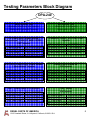
DIESEL PARTS OF AMERICA
13150 Leadwell Street, N. Hollywood, California, 91605 U.S.A.
Tel: 818-765-3344 818-765-3345 Fax: 818-765-1412
[email protected]
DPA - 240
USER’S MANUAL
DPA-240 Worldwide approved entities.
TABLE OF CONTENTS
Introduction ………………………………………………………………..page 2
General……………………………………………………………….…….page 4
Testing Parameters Block Diagram……………………………………..page 5
Installation …………………………………………………………………page 6
Pulse Box Generator Functions……………………………………...….page 10
DPA-240 Testing Method and Parts…………………………………….page 11
7.3 L HEUI Ford* Power Stroke
/ International* T444 / DT 466E
/ I530E / CAT* Injector Test………………………………...……………page 14
6.0 L & 4.5 L HEUI Ford* Power Stroke
/ International* Injector Test……………………………………………..page 18
CAT* 3126A / HEUI 3116 Injector Test…………………………………page 23
Cummins* Celect*, N-14 / M-11 EUI Injector Test……………….……page 28
Detroit Diesel Series 60* EUI Injector Test…………………………….page 36
CAT* 3406E EUI Injector Test ………………………………………….page 44
Recommendations………………………………………………………..page 52
Limited Warranty …………………………………………………………page 53
Notes…………………………………………………………………….…page 54
DIESEL PARTS OF AMERICA
13150 Leadwell Street, N. Hollywood, California, 91605 U.S.A.
2
Introduction
Thank you for your recent DPA-240 purchase. We appreciate your business and are
pleased to add your name to our growing list of customers. You have invested in the
highest quality equipment available. Now, please take a few minutes and read this
booklet. This will familiarize you with the benefits you will receive from the equipment you
just purchased and help you understand the testing routine that will be required.
This manual has been prepared especially for use in familiarizing personnel with the
design, installation and operation of this equipment. All information presented herein
should be given careful consideration to assure optimum performance of this equipment.
All information, illustrations, photographs and specifications contained in this manual are
based on the latest product information available at the time of publication. Due to
improvements or other changes, there will be some discrepancies in this manual. We
reserve the right to make product changes at any time, without notice and without
incurring any obligation to make the same or similar changes to the tester previously built
or sold.
Safety
The following definitions apply to CAUTION, IMPORTANT, and NOTE blocks found
throughout this manual;
CAUTION
Under this heading, installation and operating procedures or practices will
sssssssssssss be found that if not carefully followed may create a hazard to personnel
IMPORTANT
Under this heading, installation and operating procedures or practices will
sssssssssssss be found that if nor carefully followed may result in damage to equipment.
NOTE
Under this heading, explanatory statements will be found that need
dddddddddddddspecial emphasis to obtain the most efficient operation of this equipment.
DIESEL PARTS OF AMERICA
13150 Leadwell Street, N. Hollywood, California, 91605 U.S.A.
3
General
The DPA-240 is a standard alone machine designed to test HEUI (Hydraulically
activated electronically mechanically controlled injectors) and EUI (electronically
activated mechanically controlled injectors). It features a graduate metering system
and a comprehensive electronic control, enabling a full range of tests to be performed.
The machine incorporates a single test oil supply with fuel
and hydraulic pressures controlled individually.
Injector Control Features:
-
Auto pulse width control from 0.05 to 3 Ms equivalent to injection duration.
Shot count control up to 1000 shots, and continuous operation
HEUI Variable simulated RPM’s in a wide range of tests (from 300 to 2000 RPM)
Test tube time control from 1 sec to 60 sec.
Information Table:
Power Supply:
Fuel Pump Motor power:
Hydraulic Pressure Motor power:
Cam-Box Motor power:
Tank Capacity:
Net Weight:
Dimensions (as a square):
Fuel Pressure
Hydraulic Pressure
Graduates Volume
210-220 Volts, 60 Hertz
1 HP
7.5 HP
5 HP
200 Liters
650 Kg
172 cm X 120 cm X 80 cm
0 to 300 PSI
0 to 2000 PSI
0 to 250 ml
DPA-240 injectors capable to test:
- 7.3 L HEUI Ford* Power Stroke / International* T444 / DT 466E / I530 E / CAT Injector
- 6.0 L & 4.5 L HEUI Ford* Power Stroke / International* Injector
- CAT* 3126A / HEUI 3116 Injector
- Cummins* Celect* N-14 / M-11 EUI Injector
- Detroit Diesel Series 60* EUI Injector
- CAT* 3406E EUI Injector
DIESEL PARTS OF AMERICA
13150 Leadwell Street, N. Hollywood, California, 91605 U.S.A.
4
Testing Parameters Block Diagram
DPA-240
HEUI Injector Test
(Hydraulic Electronic Unit Injector)
Works with Hydraulic Pressure
EUI Injector Test
(Electronic Unit Injector)
Works with a CAM
7.3 L HEUI Ford* Power Stroke /
International* T444 / DT 466E / I530E /
CAT* Injector
Cummins* Celect*, N-14 / M-11 EUI
Injector
Testing Speed
Hydraulic Press.
Fuel Press.
Test Tube Time
300 to 2000 RPM
750 to 1000 PSI
60 to 150 PSI
28 to 32 sec.
6.0 L & 4.5 L HEUI Ford* Power Stroke
/ International* Injector
Testing Speed
Hydraulic Press.
Fuel Press.
Test Tube Time
300 to 2000 RPM
750 to 1000 PSI
60 to 150 PSI
28 to 32 sec.
Testing Speed
Hydraulic Press.
Fuel Press.
Test Tube Time
Detroit Diesel Series 60*
EUI Injector
Testing Speed
Hydraulic Press.
Fuel Press.
Test Tube Time
CAT* 3126A / HEUI 3116 Injector
Testing Speed
Hydraulic Press.
Fuel Press.
Test Tube Time
300 to 2000 RPM
750 to 1000 PSI
60 to 150 PSI
28 to 32 sec.
900 RPM Fixed
Not Available
60 to 150 PSI
28 to 32 sec.
900 RPM Fixed
Not Available
60 to 150 PSI
28 to 32 sec.
CAT* 3406E
EUI Injector
Testing Speed
Hydraulic Press.
Fuel Press.
Test Tube Time
DIESEL PARTS OF AMERICA
13150 Leadwell Street, N. Hollywood, California, 91605 U.S.A.
900 RPM Fixed
Not Available
60 to 150 PSI
28 to 32 sec.
5
Installation
For your safety, and to maximize the service life of your equipment, it is very important to
take a few moments before you operate the tester to check its condition. Be sure to take
care of any problem you find, before you operate the tester.
IMPORTANT
Every step must be chronologically followed in order to get the best
ddddddddddd possible results.
The DPA 240 basically needs three main conditions to work, Hydraulic oil (for the 200 liter
tank), gear transmission oil (for the CAM-BOX), and Electrical Power Supply.
1. - Fill the oil tank with 180 liters with any of the next Hydraulic oil Brand specifications:
Mobil*
Esso*
Elf*
Quaker*
Texaco*
Shem*
DTE - 24
NUTO - H32
DTH32 HF - 2
SPEED OIL LIGHT
RANDO 32
HYDRO-32
NOTE
In order to maintain always the same oil temperature it is necessary
ddddddddddddddddto fill the tank with at least 180 oil liters, (check with DIP STICK)
Remove the acrylic protection and fill the Hydraulic oil in the tank as shown in the picture:
Fill the oil in this Area.
DIESEL PARTS OF AMERICA
13150 Leadwell Street, N. Hollywood, California, 91605 U.S.A.
6
2. - Fill the CAM BOX with 2 liters of gear transmission oil with next gear transmission oil
Brand specifications (GENERAL OIL, SAE 250):
Quaker State*
Texaco*
Shell*
Green Oil SAE 250
Thuban SAE 250
Dentax SAE 250
The gear transmission Oil must be filled in the CAM BOX as shown in the picture:
IMPORTANT
Do not overfill the CAM BOX with the gear transmission oil, if there is
dddddddddddd dd too much oil it can cause oil leakage from the CAM BOX at work
3.- Now we proceed to connect the DPA-240 to the electrical power supply.
The DPA-240 power supply specification is:
210-220 Volts @ 60 Hertz.
With NO ground/neutral connection (all the motors from the pumps and CAM BOX such
as the pulse box generator are 3 phases electrically wired and does not need an
electrically ground/neutral connection as in accordance with the National Electrical Code)
CAUTION
Risk of electric shock may cause death or serious body injury such
ddddddddddddddddas electrical damage to the tester
DIESEL PARTS OF AMERICA
13150 Leadwell Street, N. Hollywood, California, 91605 U.S.A.
7
Power supply must be connected as shown in the next electrical diagram:
Main Switch
After we have connected the DPA-240 tester to the electrical supply, we have to check
that the electrical motors are correctly spindle orientated in order for the tester to work
properly. We can check this with this singles steps:
1.- Open the CAM-BOX side door and turn on the CAM BOX, with the sliding switch in the
“ON” direction and Immediately slide the switch to “OFF position, as shown in the picture
DIESEL PARTS OF AMERICA
13150 Leadwell Street, N. Hollywood, California, 91605 U.S.A.
8
2. - Verify that the spindle direction of the CAM BOX is clockwise as shown and close de
CAM-BOX side door:
CAUTION
Keep out from all moving parts when installing or testing with the
ddddddddddddd machine
If the spindle direction of the CAM BOX is correct, the DPA-240 is ready to start testing
Injectors, if not, disconnect the main switch, and correct the electrical supply diagram
connections as shown, then connect the main switch and repeat the last 2 steps.
DIESEL PARTS OF AMERICA
13150 Leadwell Street, N. Hollywood, California, 91605 U.S.A.
9
Pulse Box Generator Functions
The pulse box generator has 3 main selectable parameters, but in order to understand
them, first of all we have to recognize the Pulse Box panel functions and block diagram.
NOTE
The test tubes filler button is independent from all the other pulse box
ssssssssssssssifunctions, and once the delivery time starts running, it is not possible to
ssssssssssssssistop this function until the delivery time finishes.
DIESEL PARTS OF AMERICA
13150 Leadwell Street, N. Hollywood, California, 91605 U.S.A.
10
DPA-240 testing method and Parts
For testing EUI / HEUI injectors, this is the main methodology:
IMPORTANT
Every step must be chronologically followed in order to get the best
ddddddddddd possible results.
1.- Clean the injector / injectors in its internal / external parts, before testing, to
avoid oil contamination.
2.- Place the injector / injectors in its testing place (CAM BOX, or HEUI adapters) with
its accessories (if necessary)
3.- Turn on the Pulse Generator Box and set its parameters (HEUI or EUI mode,
RPM’s <- just in the HEUI mode, Test tube times, etc), then check that the solenoid is
really working (you can check this by the sound it generates when opening and closing
the poppet valves)
4.- Turn on the Hydraulics and fuel pump or just the fuel pump (depending on the
testing system, EUI or HEUI), and rise to the desired pressure value.
5.- Turn on the CAM BOX (only when testing EUI systems)
NOTE
Remember that the EUI injector systems only works with a CAM, and
ssssssssssssiFuel pressure
6.- Check the fuel delivery in the test tubes, pressing the “Start Test” button.
7.- After finishing the test / tests, turn off the Hydraulics and fuel pump or just the fuel
ddddi pump (depending on the testing system, EUI or HEUI).
8.- Turn off the CAM BOX (only when testing EUI systems)
d
9.- Turn off the Pulse Generator Box and Main Switch after all the testing has been
performed
10.- Place their accessories / protective case (acrylics, dummy injectors, etc)
DIESEL PARTS OF AMERICA
13150 Leadwell Street, N. Hollywood, California, 91605 U.S.A.
11
Recognize the main DPA-240 controls panel
Hydraulic Pressure switch
Fuel Pump switch
CAM BOX switch
Hydraulic Pressure Regulator and Manometer
Fuel Pump Pressure Regulator and Manometer
Pulse Box switch
DIESEL PARTS OF AMERICA
13150 Leadwell Street, N. Hollywood, California, 91605 U.S.A.
12
CAM BOX Description
The CAM BOX works with a universal CAM, capable to test virtually all EUI Injectors and
EUP (Electronic Unit Pumps) available on the market (If you need more testing adapters
for other types of injectors, or EUP pumps, please ask for more information with your local
DPA Dealer), this eliminates the assembly and disassembly job of changing CAMS, since
1 CAM works with all EUI injectors and EUP pumps.
The diagram of the CAM BOX is as shown:
A CAM is dragged by the electrical motor, which is in contact with a roller; this roller on
the top has attached a link that must be connected to the EUI Injector / EUP pump.
NOTE
In this DPA-240 version, this CAM BOX only works at 900 RPM’s
DIESEL PARTS OF AMERICA
13150 Leadwell Street, N. Hollywood, California, 91605 U.S.A.
13
HEUI Injector Tests
7.3 L HEUI Ford* Power Stroke / International* T444 / DT 466E / I530E / CAT* Injector
MODE:
HEUI
Required
Parameter
Parameter
Values
Recomended
Value
Hydraulic
Pressure
Fuel
Pressure
Test Tube
Time
Pulse Box
RPM's
YES
YES
YES
YES
750 to
1000 PSI
60 to
150 PSI
28 to
32 Sec
750 PSI
100 PSI
30 Sec
300 to
2000 RPM
Low, 300 RPM
Mid, 900 RPM
High, 1200 RPM
Able to test injectors at a time: 6
Accessories to be used for testing these injectors
6- Dummy Injectors
6- Injector Retaining Adapters
Testing Sequence:
IMPORTANT
Every step must be chronologically followed in order to get the best
ddddddddddd possible results.
1.- Take out the dummy injectors from the HEUI testing adapters.
DIESEL PARTS OF AMERICA
13150 Leadwell Street, N. Hollywood, California, 91605 U.S.A.
14
NOTE
You can test 6 injectors at a time or less number of injectors, placing in
sssssssssssssssithe missing adapters the Dummy injectors, these injectors will play as a
ddddddddddddddplug, for not loosing hydraulic pressure. Never leave an empty
ddddddddddddi adapter space when testing.
IMPORTANT
Before testing, make sure that all the injectors are cleaned in its inside /
sssssssssssssssioutside parts, this is to avoid oil contamination
2.- Place the injector/s in the HEUI adapter spaces, and make sure that they are strongly
clamped to the adapter base with the Injector retaining adapters. (Also Dummy injector/s,
if placed), plug them with the provided RED TAG harnesses (where available) and cover
them with the acrylic protection as shown in the picture. (Also make sure that the BLUE
TAG Harness, the GREEN and YELLOW TAG harnesses are not connected so as in
Short Circuit)
3.- Turn on the Pulse Box, and set the testing parameters (HEUI mode, Test tube delivery
time and RPM’s). Now you will hear the sound of the Injector/s Poppet Valves working at
the specified RPM’s.
4.- Move the Fuel Pressure switch to “ON” position, and rise the fuel pressure with the fuel
pressure valve (moving clockwise) to the desired fuel pressure (we recommend 100 PSI)
as shown in picture.
DIESEL PARTS OF AMERICA
13150 Leadwell Street, N. Hollywood, California, 91605 U.S.A.
15
5.- Press the Hydraulic pump switch to “ON”, and rise the oil pressure with the oil
pressure valve (moving clockwise) to the desired oil pressure (we recommend 750 PSI)
as shown in picture.
6.- Now injectors should start working. You will see how the injector/s releases oil
pressure in the adapters area, and they start to deliver oil (that plays the fuel role), in the
back area of the test tubes, as shown in picture.
NOTE
When testing for the very first time, perform the test with clean and precssssssssssssi checked working injectors.
7.- Leave working this injector/s for about 20 seconds before checking fuel delivery, this is
for the injector/s to eliminate air bubbles from its mechanism.
8.- Press the “Start Test” button in the Pulse Box panel to check the fuel delivery in the
test tubes for the desired pre-set time, then drain the oil from the test tubes.
9.- Repeat step 8 as many times as required until the fuel delivery reading gets stable.
10.- Change the RPM’s in the Pulse Box panel as desired (Low, mid or high RPM’s), and
re-arrange the fuel and oil pressures to the desired parameters, this helps us to get
steady fuel delivery readings (moving the pressure valves clockwise or counterclockwise), and repeat step 8 as many times as required until the fuel delivery readings
gets stable in each desired RPM Parameter.
DIESEL PARTS OF AMERICA
13150 Leadwell Street, N. Hollywood, California, 91605 U.S.A.
16
NOTE
Take note of the fuel delivery readings and testing parameters and
dddddddddddd compare between them. This is the main purpose of the tester. This
itester does not fix injectors, just compares between them
Turn off sequence
11.- After all testing has been performed, we proceed to turn off the tester. First, decrease
the oil pressure with the oil pressure valve (moving counter-clockwise) to almost 0 PSI,
and press the Hydraulic pump switch to “OFF”. As shown in picture.
12.- Decrease the fuel pressure with the fuel pressure valve (moving counter- clockwise)
to almost 0 PSI, then move the Fuel Pressure switch to “OFF” position. As shown in
picture.
13.- Turn “OFF” the pulse box
14.- Unplug Harnesses, take out the injectors and then place the Dummy Injectors in the
adapter spaces, and cover them with the acrylic protection. This is for avoiding dust or
contamination in the internal piping system.
15.- Testing cycle finished.
DIESEL PARTS OF AMERICA
13150 Leadwell Street, N. Hollywood, California, 91605 U.S.A.
17
6.0 L & 4.5 L HEUI Ford* Power Stroke / International* Injector
MODE:
HEUI
Required
Parameter
Parameter
Values
Recomended
Value
Hydraulic
Pressure
Fuel
Pressure
Test Tube
Time
Pulse Box
RPM's
YES
YES
YES
YES
750 to
1000 PSI
60 to
150 PSI
28 to
32 Sec
750 PSI
100 PSI
30 Sec
300 to
2000 RPM
Low, 300 RPM
Mid, 900 RPM
High, 1200 RPM
Able to test injectors at a time: 1
Accessories to be used for testing these injectors
4- Dummy Injectors
1- Hose Oil Supply Injector
6- Injector Retaining Adapters
1- 6.0 L & 4.5 L HEUI Adapter
DIESEL PARTS OF AMERICA
13150 Leadwell Street, N. Hollywood, California, 91605 U.S.A.
18
Testing Sequence:
IMPORTANT
Every step must be chronologically followed in order to get the best
ddddddddddd possible results.
1.- Take out the dummy injectors from the HEUI testing adapters.
IMPORTANT
Before testing, make sure that all the injectors are cleaned in its inside /
sssssssssssssssioutside parts, this is to avoid oil contamination
2.- Place the 6.0 L & 4.5 L HEUI Adapter in the first HEUI adapter space (from right to
left position), then place the 6.0 L or 4.5 L injector over it and press it until it reaches its
final position, place also the hose oil supply injector in the last adapter space. Place the
oil supply plug from the hose oil supply injector to the top of the 6.0 L or 4.5 L injector
and make sure that they are strongly clamped to the adapter base with the Injector
retaining adapters. (Also place the Dummy injectors in the 2, 3, 4, 5, positions from right
to left), as shown in the picture.
2.1- Plug the injector with the provided BLUE TAG wires as shown in the picture, and
cover it with the acrylic protection. (Also make sure that the RED TAG Harnesses, the
GREEN and YELLOW TAG wires are not connected so as in Short Circuit)
d
d
2 pair of wires from 1 solenoid must
be connected with 2 pair of wires d
from the pulse box in the inj, harness
d
d
2 pair of wires from 1 solenoid must
be connected with 2 pair of wires d
from the pulse box in the inj harness
DIESEL PARTS OF AMERICA
13150 Leadwell Street, N. Hollywood, California, 91605 U.S.A.
19
3.- Turn on the Pulse Box, and set the testing parameters (HEUI mode, Test tube delivery
time and RPM’s). Now you will hear the sound of the Injector Poppet Valve working at the
specified RPM’s.
4.- Move the Fuel Pressure switch to “ON” position, and rise the fuel pressure with the fuel
pressure valve (moving clockwise) to the desired fuel pressure (we recommend 100 PSI)
as shown in picture.
5.- Press the Hydraulic pump switch to “ON”, and rise the oil pressure with the oil
pressure valve (moving clockwise) to the desired oil pressure (we recommend 750 PSI)
as shown in picture.
6.- Now injector should start working. You will see how the injector releases oil pressure in
the adapters area, and it start to deliver oil (that plays the fuel role), in the back area of the
test tubes, as shown in picture.
DIESEL PARTS OF AMERICA
13150 Leadwell Street, N. Hollywood, California, 91605 U.S.A.
20
NOTE
When testing for the very first time, perform the test with clean and precssssssssssssi checked working injector.
7.- Leave working the injector for about 20 seconds before checking fuel delivery, this is
for the injector to eliminate air bubbles from its mechanism.
8.- Press the “Start Test” button in the Pulse Box panel to check the fuel delivery in the
test tubes for the desired pre-set time, then drain the oil from the test tubes.
9.- Repeat step 8 as many times as required until the fuel delivery reading gets stable.
10.- Change the RPM’s in the Pulse Box panel as desired (Low, mid or high RPM’s), and
re-arrange the fuel and oil pressures to the desired parameters, this helps us to get
steady fuel delivery readings (moving the pressure valves clockwise or counterclockwise), and repeat step 8 as many times as required until the fuel delivery readings
gets stable in each desired RPM Parameter.
NOTE
Take note of the fuel delivery readings and testing parameters and
dddddddddddd compare between them. This is the main purpose of the tester. This
itester does not fix injectors, just compares between them
Turn off sequence
11.- After all testing has been performed, we proceed to turn off the tester. First, decrease
the oil pressure with the oil pressure valve (moving counter-clockwise) to almost 0 PSI,
and press the Hydraulic pump switch to “OFF”. As shown in picture.
DIESEL PARTS OF AMERICA
13150 Leadwell Street, N. Hollywood, California, 91605 U.S.A.
21
12.- Decrease the fuel pressure with the fuel pressure valve (moving counter- clockwise)
to almost 0 PSI, then move the Fuel Pressure switch to “OFF” position. As shown in
picture.
13.- Turn “OFF” the pulse box.
14.- Unplug Harness, take out the injector, the hose Oil Supply Injector and then place the
Dummy Injectors in the adapter spaces, and cover them with the acrylic protection. This is
for avoiding dust or contamination in the internal piping system.
15.- Testing cycle finished.
DIESEL PARTS OF AMERICA
13150 Leadwell Street, N. Hollywood, California, 91605 U.S.A.
22
CAT* 3126A / HEUI 3116 Injector
MODE:
HEUI
Required
Parameter
Parameter
Values
Recomended
Value
Hydraulic
Pressure
Fuel
Pressure
Test Tube
Time
Pulse Box
RPM's
YES
YES
YES
YES
750 to
1000 PSI
60 to
150 PSI
28 to
32 Sec
750 PSI
100 PSI
30 Sec
300 to
2000 RPM
Low, 300 RPM
Mid, 900 RPM
High, 1200 RPM
Able to test injectors at a time: 1
Accessories to be used for testing these injectors
4- Dummy Injectors
6- Injector Retaining Adapters
1- Hose Oil Supply Injector
1- CAT* 3126A / 3116 HEUI Adapter
DIESEL PARTS OF AMERICA
13150 Leadwell Street, N. Hollywood, California, 91605 U.S.A.
23
Testing Sequence:
IMPORTANT
Every step must be chronologically followed in order to get the best
ddddddddddd possible results.
1.- Take out the dummy injectors from the HEUI testing adapters.
IMPORTANT
Before testing, make sure that all the injectors are cleaned in its inside /
sssssssssssssssioutside parts, this is to avoid oil contamination
2.- Place the CAT* 3126A / HEUI 3116 Injector in the first HEUI adapter space (from right
to left position), place also the hose oil supply injector in the last adapter space. Place
the oil supply plug from the hose oil supply injector to the top of the CAT* 3126A / HEUI
3116 Injector and make sure that they are strongly clamped to the adapter base with the
Injector retaining adapters. (Also place the Dummy injectors in the 2, 3, 4, 5, positions
from right to left), as shown in the picture.
2.1- Plug the Injector with the provided RED TAG harness and cover them with the acrylic
protection as shown in the picture. (Also make sure that the BLUE TAG Harness, the
GREEN and YELLOW TAG harnesses are not connected so as in Short Circuit)
DIESEL PARTS OF AMERICA
13150 Leadwell Street, N. Hollywood, California, 91605 U.S.A.
24
3.- Turn on the Pulse Box, and set the testing parameters (HEUI mode, Test tube delivery
time and RPM’s). Now you will hear the sound of the Injector Poppet Valve working at the
specified RPM’s.
4.- Move the Fuel Pressure switch to “ON” position, and rise the fuel pressure with the fuel
pressure valve (moving clockwise) to the desired fuel pressure (we recommend 100 PSI)
as shown in picture.
5.- Press the Hydraulic pump switch to “ON”, and rise the oil pressure with the oil
pressure valve (moving clockwise) to the desired oil pressure (we recommend 750 PSI)
as shown in picture.
6.- Now injector should start working. You will see how the injector releases oil pressure in
the adapters area, and it start to deliver oil (that plays the fuel role), in the back area of the
test tubes, as shown in picture.
DIESEL PARTS OF AMERICA
13150 Leadwell Street, N. Hollywood, California, 91605 U.S.A.
25
NOTE
When testing for the very first time, perform the test with clean and precssssssssssssi checked working injector.
7.- Leave working the injector for about 20 seconds before checking fuel delivery, this is
for the injector to eliminate air bubbles from its mechanism.
8.- Press the “Start Test” button in the Pulse Box panel to check the fuel delivery in the
test tubes for the desired pre-set time, then drain the oil from the test tubes.
9.- Repeat step 8 as many times as required until the fuel delivery reading gets stable.
10.- Change the RPM’s in the Pulse Box panel as desired (Low, mid or high RPM’s), and
re-arrange the fuel and oil pressures to the desired parameters, this helps us to get
steady fuel delivery readings (moving the pressure valves clockwise or counterclockwise), and repeat step 8 as many times as required until the fuel delivery readings
gets stable in each desired RPM Parameter.
NOTE
Take note of the fuel delivery readings and testing parameters and
dddddddddddd compare between them. This is the main purpose of the tester. This
itester does not fix injectors, just compares between them
Turn off sequence
11.- After all testing has been performed, we proceed to turn off the tester. First, decrease
the oil pressure with the oil pressure valve (moving counter-clockwise) to almost 0 PSI,
and press the Hydraulic pump switch to “OFF”. As shown in picture.
DIESEL PARTS OF AMERICA
13150 Leadwell Street, N. Hollywood, California, 91605 U.S.A.
26
12.- Decrease the fuel pressure with the fuel pressure valve (moving counter- clockwise)
to almost 0 PSI, then move the Fuel Pressure switch to “OFF” position. As shown in
picture.
13.- Turn “OFF” the pulse box.
14.- Unplug Harness, take out the injector, the hose Oil Supply Injector and then place the
Dummy Injectors in the adapter spaces, and cover them with the acrylic protection. This is
for avoiding dust or contamination in the internal piping system.
15.- Testing cycle finished.
DIESEL PARTS OF AMERICA
13150 Leadwell Street, N. Hollywood, California, 91605 U.S.A.
27
EUI Injector Tests
Cummins* Celect*, N-14 / M-11 EUI Injector
MODE:
EUI
Required
Parameter
Parameter
Values
Recomended
Value
Hydraulic
Pressure
Fuel
Pressure
Test Tube
Time
Pulse Box
RPM's
NO
YES
YES
AUTO
-
60 to
150 PSI
28 to
32 Sec
-
100 PSI
30 Sec
900 RPM
Fixed
900 RPM
Fixed
Able to test injectors at a time: 1
Accessories to be used for testing these injectors
1 Cummins* Celect*, N-14 / M-11
EUI Injector Adapter
1 Cummins* Celect*, N-14 / M-11
EUI Injector Link screw (concaves head)
DIESEL PARTS OF AMERICA
13150 Leadwell Street, N. Hollywood, California, 91605 U.S.A.
28
Testing Sequence:
IMPORTANT
Every step must be chronologically followed in order to get the best
ddddddddddd possible results.
1.- Make sure that the 6 Dummy injectors are placed in its correct positions (adapter
spaces) and verify that they are strongly clamped to the adapter base with the Injector
retaining adapters as shown. (this is to avoid pressure loose in the oil piping) Remember
always to perform this step before testing any EUI injector
IMPORTANT
Before testing, make sure that all the injectors are cleaned in its inside /
sssssssssssssssioutside parts, this is to avoid oil contamination
2.- Cover the external O-ring’s with yellow or green automotive grease and place the
Cummins Celect Injector in its correct adapter (N-14 or M-11 type) as shown in picture
DIESEL PARTS OF AMERICA
13150 Leadwell Street, N. Hollywood, California, 91605 U.S.A.
29
3.- Place the EUI injector with its adapter in the CAM BOX, and strongly tighten the
retaining screws, as shown in picture.
4.- Open the CAM BOX side door where the CAM shaft pulley is located.
5.- Spindle by hand the CAM shaft with the CAM shaft pulley in order to find the
LOWEST CAM PROFILE POINT (in other words, the roller part of the CAM BOX
where the link is placed should be as far as possible from the Injector follower
part), as shown in the pictures.
DIESEL PARTS OF AMERICA
13150 Leadwell Street, N. Hollywood, California, 91605 U.S.A.
30
6.- Then, assembly the Cummins* Celect*, N-14 / M-11 EUI Injector Link screw to the
roller, till it slightly touches the injector follower part, as shown in picture
Slight Contact only.
7.- Then screw the Cummins* Celect*, N-14 / M-11 EUI Injector Link until the follower
part of the injector diminish 2 linear millimeters (more less 2 screw rounds after the link
screw slightly touches the injector follower part), and tighten the lock nut to the roller, as
shown in picture.
8.- Spindle by hand the CAM shaft with the CAM shaft pulley to verify that the CAM has
free rotary movement and free Injector linear movement (It can happens that the Injector
is too much tightened with the link screw that it is not able to move or to rotate and gets
clogged as in the extreme right diagram) as shown in picture.
CAM-BOX Link
Injector Spring Follower
DIESEL PARTS OF AMERICA
13150 Leadwell Street, N. Hollywood, California, 91605 U.S.A.
31
IMPORTANT
If the CAM DOES NOT HAVE FREELY ROTARY / INJECTOR LINEAR
ddiidddddddddiMOVEMENT, after CAM BOX switch is turned “ON”, it could cause
sssssssssssssssseveral damage to the CAM BOX electrical motor / pulleys / bands.
9.- If the CAM has freely rotary / injector linear movement, close the CAM BOX side door
in order to continue.
d
IMPORTANT
Risk of death or serious injury can be caused if the CAM BOX side door
is not closed before the CAM BOX switch is turned “ON”
10.- If the CAM DOES NOT HAVE FREELY ROTARY / INJECTOR LINEAR
MOVEMENT, repeat step No. 7 with a less distance ( 1 linear millimeter or less) until the
CAM has freely rotary / injector linear movement, and then follow step No. 9
11.- Then place the CAM BOX nozzle catcher to the Celect*, N-14 / M-11 EUI Injector
nozzle, and give a normal strength tighten to the nozzle catcher as shown in picture (too
much strength tighten in the nozzle catcher could cause injector to pull out from its
adapter, and injector will not work)
12.- Now, plug the fuel pressure hose and fuel return hose (if available) to the Celect*,
N-14 / M-11 EUI Injector adapter.
DIESEL PARTS OF AMERICA
13150 Leadwell Street, N. Hollywood, California, 91605 U.S.A.
32
13.- Plug the Injector with the provided GREEN TAG wire and cover them with the acrylic
protection as shown in the picture. (Also make sure that the BLUE TAG Harness, the RED
and YELLOW TAG harnesses / wires are not connected so as in Short Circuit)
14.- Turn on the Pulse Box, and set the testing mode to EUI mode, then open the CAM
BOX side door and spindle by hand the CAM Shaft pulley several times (this is for the
operator to hear the sound of the Injector Poppet Valve working with the solenoid.). RPM
tachometer must mark RPM=000X10 Then set the test tube delivery time to the desired
time, then close the CAM BOX side door.
15.- Move the CAM BOX switch to “ON” position as shown in picture, then CAM BOX
motor will start working.
CAUTION
Keep out from all moving parts when installing or testing with the
dddddd ddd machine
DIESEL PARTS OF AMERICA
13150 Leadwell Street, N. Hollywood, California, 91605 U.S.A.
33
16.- Move the Fuel Pressure switch to “ON” position, and rise the fuel pressure with the
fuel pressure valve (moving clockwise) to the desired fuel pressure (we recommend 100
PSI) as shown in picture.
17.- Now injector should start working and it starts to deliver oil (that plays the fuel role), in
the back area of the test tubes, as shown in picture.
NOTE
When testing for the very first time, perform the test with clean and precssssssssssssi checked working injector.
18.- Leave working the injector for about 20 seconds before checking fuel delivery, this is
for the injector to eliminate air bubbles from its mechanism.
19.- Press the “Start Test” button in the Pulse Box panel to check the fuel delivery in the
test tube for the desired pre-set time, then drain the oil from the test tube.
20.- Repeat step 19 as many times as required until the fuel delivery reading gets stable.
NOTE
Take note of the fuel delivery readings and testing parameters and
dddddddddddd compare between them. This is the main purpose of the tester. This
itester does not fix injectors, just compares between them
DIESEL PARTS OF AMERICA
13150 Leadwell Street, N. Hollywood, California, 91605 U.S.A.
34
Turn off sequence
21.- After all testing has been performed, we proceed to turn off the tester. First, decrease
the fuel pressure with the fuel pressure valve (moving counter- clockwise) to almost 0
PSI, then move the Fuel Pressure switch to “OFF” position. As shown in picture.
22.- Turn “OFF” CAM BOX switch then Turn “OFF” pulse box switch.
14.- Unplug Harness, take out the injector starting with the CAM BOX nozzle catcher, then
the screw link, and at the end with the Injector Adapter.
23.- Testing cycle finished.
DIESEL PARTS OF AMERICA
13150 Leadwell Street, N. Hollywood, California, 91605 U.S.A.
35
Detroit Diesel Series 60* EUI Injector
MODE:
EUI
Required
Parameter
Parameter
Values
Recomendad
Value
Hydraulic
Pressure
Fuel
Pressure
Test Tube
Time
Pulse Box
RPM's
NO
YES
YES
AUTO
-
60 to
150 PSI
28 to
32 Sec
-
100 PSI
30 Sec
900 RPM
Fixed
900 RPM
Fixed
Able to test injectors at a time: 1
Accessories to be used for testing these injectors
1 Detroit Diesel Series 60*
EUI Injector Adapter
1 Detroit Diesel Series 60*
EUI Injector Link screw (Planar head)
DIESEL PARTS OF AMERICA
13150 Leadwell Street, N. Hollywood, California, 91605 U.S.A.
36
Testing Sequence:
IMPORTANT
Every step must be chronologically followed in order to get the best
ddddddddddd possible results.
1.- Make sure that the 6 Dummy injectors are placed in its correct positions (adapter
spaces) and verify that they are strongly clamped to the adapter base with the Injector
retaining adapters as shown. (this is to avoid pressure loose in the oil piping) Remember
always to perform this step before testing any EUI injector
IMPORTANT
Before testing, make sure that all the injectors are cleaned in its inside /
sssssssssssssssioutside parts, this is to avoid oil contamination
2.- Cover the external O-ring’s with yellow or green automotive grease and place the
Detroit Diesel Series 60* Injector in its correct adapter as shown in picture
DIESEL PARTS OF AMERICA
13150 Leadwell Street, N. Hollywood, California, 91605 U.S.A.
37
3.- Place the EUI injector with its adapter in the CAM BOX, and strongly tighten the
retaining screws, as shown in picture.
4.- Open the CAM BOX side door where the CAM shaft pulley is located.
5.- Spindle by hand the CAM shaft with the CAM shaft pulley in order to find the
LOWEST CAM PROFILE POINT (in other words, the roller part of the CAM BOX
where the link is placed should be as far as possible from the Injector follower
part), as shown in the pictures.
DIESEL PARTS OF AMERICA
13150 Leadwell Street, N. Hollywood, California, 91605 U.S.A.
38
6.- Then, assembly the Detroit Diesel Series 60* EUI Injector Link screw to the roller, till
it slightly touches the injector follower part, as shown in picture
Slight Contact only.
7.- Then screw the Detroit Diesel Series 60* EUI Injector Link until the follower part of
the injector diminish 2 linear millimeters (more less 2 screw rounds after the link screw
slightly touches the injector follower part), and tighten the lock nut to the roller, as shown
in picture.
8.- Spindle by hand the CAM shaft with the CAM shaft pulley to verify that the CAM has
free rotary movement and free Injector linear movement (It can happens that the Injector
is too much tightened with the link screw that it is not able to move or to rotate and gets
clogged as in the extreme right diagram) as shown in picture.
CAM-BOX Link
Injector Spring Follower
DIESEL PARTS OF AMERICA
13150 Leadwell Street, N. Hollywood, California, 91605 U.S.A.
39
IMPORTANT
If the CAM DOES NOT HAVE FREELY ROTARY / INJECTOR LINEAR
ddiidddddddddiMOVEMENT, after CAM BOX switch is turned “ON”, it could cause
sssssssssssssssseveral damage to the CAM BOX electrical motor / pulleys / bands.
9.- If the CAM has freely rotary / injector linear movement, close the CAM BOX side door
in order to continue.
d
IMPORTANT
Risk of death or serious injury can be caused if the CAM BOX side door
is not closed before the CAM BOX switch is turned “ON”
10.- If the CAM DOES NOT HAVE FREELY ROTARY / INJECTOR LINEAR
MOVEMENT, repeat step No. 7 with a less distance ( 1 linear millimeter or less) until the
CAM has freely rotary / injector linear movement, and then follow step No. 9
11.- Then place the CAM BOX nozzle catcher to the Detroit Diesel Series 60* EUI
Injector nozzle, and give a normal strength tighten to the nozzle catcher as shown in
picture (too much strength tighten in the nozzle catcher could cause injector to pull
out from its adapter, and injector will not work)
12.- Now, plug the fuel pressure hose and to the Detroit Diesel Series 60* EUI Injector
adapter.
DIESEL PARTS OF AMERICA
13150 Leadwell Street, N. Hollywood, California, 91605 U.S.A.
40
13.- Plug the Injector with the provided YELLOW TAG wire and cover them with the
acrylic protection as shown in the picture. (Also make sure that the BLUE TAG Harness,
the RED and GREEN TAG harnesses / wires are not connected so as in Short Circuit)
14.- Turn on the Pulse Box, and set the testing mode to EUI mode, then open the CAM
BOX side door and spindle by hand the CAM Shaft pulley several times (this is for the
operator to hear the sound of the Injector Poppet Valve working with the solenoid.). RPM
tachometer must mark RPM=000X10 Then set the test tube delivery time to the desired
time, then close the CAM BOX side door.
15.- Move the CAM BOX switch to “ON” position as shown in picture, then CAM BOX
motor will start working.
CAUTION
Keep out from all moving parts when installing or testing with the
dddddd ddd machine
DIESEL PARTS OF AMERICA
13150 Leadwell Street, N. Hollywood, California, 91605 U.S.A.
41
16.- Move the Fuel Pressure switch to “ON” position, and rise the fuel pressure with the
fuel pressure valve (moving clockwise) to the desired fuel pressure (we recommend 100
PSI) as shown in picture.
17.- Now injector should start working and it starts to deliver oil (that plays the fuel role), in
the back area of the test tubes, as shown in picture.
NOTE
When testing for the very first time, perform the test with clean and precssssssssssssi checked working injector.
18.- Leave working the injector for about 20 seconds before checking fuel delivery, this is
for the injector to eliminate air bubbles from its mechanism.
19.- Press the “Start Test” button in the Pulse Box panel to check the fuel delivery in the
test tube for the desired pre-set time, then drain the oil from the test tube.
20.- Repeat step 19 as many times as required until the fuel delivery reading gets stable.
NOTE
Take note of the fuel delivery readings and testing parameters and
dddddddddddd compare between them. This is the main purpose of the tester. This
itester does not fix injectors, just compares between them
DIESEL PARTS OF AMERICA
13150 Leadwell Street, N. Hollywood, California, 91605 U.S.A.
42
Turn off sequence
21.- After all testing has been performed, we proceed to turn off the tester. First, decrease
the fuel pressure with the fuel pressure valve (moving counter- clockwise) to almost 0
PSI, then move the Fuel Pressure switch to “OFF” position. As shown in picture.
22.- Turn “OFF” CAM BOX switch then Turn “OFF” pulse box switch.
14.- Unplug Harness, take out the injector starting with the CAM BOX nozzle catcher, then
the screw link, and at the end with the Injector Adapter.
23.- Testing cycle finished.
DIESEL PARTS OF AMERICA
13150 Leadwell Street, N. Hollywood, California, 91605 U.S.A.
43
CAT* 3406E EUI Injector
MODE:
EUI
Required
Parameter
Parameter
Values
Recomended
Value
Hydraulic
Pressure
Fuel
Pressure
Test Tube
Time
Pulse Box
RPM's
NO
YES
YES
AUTO
-
60 to
150 PSI
28 to
32 Sec
-
100 PSI
30 Sec
900 RPM
Fixed
900 RPM
Fixed
Able to test injectors at a time: 1
Accessories to be used for testing these injectors
1 CAT* 3406E EUI Injector Adapter
1 CAT* 3406E EUI Injector Link screw
ssssssssssssssssssssssssssssssssssssss(Planar Head, same as Series 60 Link Screw)
DIESEL PARTS OF AMERICA
13150 Leadwell Street, N. Hollywood, California, 91605 U.S.A.
44
Testing Sequence:
IMPORTANT
Every step must be chronologically followed in order to get the best
ddddddddddd possible results.
1.- Make sure that the 6 Dummy injectors are placed in its correct positions (adapter
spaces) and verify that they are strongly clamped to the adapter base with the Injector
retaining adapters as shown. (this is to avoid pressure loose in the oil piping) Remember
always to perform this step before testing any EUI injector
IMPORTANT
Before testing, make sure that all the injectors are cleaned in its inside /
sssssssssssssssioutside parts, this is to avoid oil contamination
2.- Cover the external O-ring’s with yellow or green automotive grease and place the
CAT* 3406E EUI Injector in its correct adapter as shown in picture
DIESEL PARTS OF AMERICA
13150 Leadwell Street, N. Hollywood, California, 91605 U.S.A.
45
3.- Place the EUI injector with its adapter in the CAM BOX, and strongly tighten the
retaining screws, as shown in picture.
4.- Open the CAM BOX side door where the CAM shaft pulley is located.
5.- Spindle by hand the CAM shaft with the CAM shaft pulley in order to find the
LOWEST CAM PROFILE POINT (in other words, the roller part of the CAM BOX
where the link is placed should be as far as possible from the Injector follower
part), as shown in the pictures.
DIESEL PARTS OF AMERICA
13150 Leadwell Street, N. Hollywood, California, 91605 U.S.A.
46
6.- Then, assembly the CAT* 3406E EUI Injector Link screw to the roller, till it slightly
touches the injector follower part, as shown in picture
Slight Contact only.
7.- Then screw the CAT* 3406E EUI Injector Link until the follower part of the injector
diminish 2 linear millimeters (more less 2 screw rounds after the link screw slightly
touches the injector follower part), and tighten the lock nut to the roller, as shown in
picture.
8.- Spindle by hand the CAM shaft with the CAM shaft pulley to verify that the CAM has
free rotary movement and free Injector linear movement (It can happens that the Injector
is too much tightened with the link screw that it is not able to move or to rotate and gets
clogged as in the extreme right diagram) as shown in picture.
CAM-BOX Link
Injector Spring Follower
DIESEL PARTS OF AMERICA
13150 Leadwell Street, N. Hollywood, California, 91605 U.S.A.
47
IMPORTANT
If the CAM DOES NOT HAVE FREELY ROTARY / INJECTOR LINEAR
ddiidddddddddiMOVEMENT, after CAM BOX switch is turned “ON”, it could cause
sssssssssssssssseveral damage to the CAM BOX electrical motor / pulleys / bands.
9.- If the CAM has freely rotary / injector linear movement, close the CAM BOX side door
in order to continue.
d
IMPORTANT
Risk of death or serious injury can be caused if the CAM BOX side door
is not closed before the CAM BOX switch is turned “ON”
10.- If the CAM DOES NOT HAVE FREELY ROTARY / INJECTOR LINEAR
MOVEMENT, repeat step No. 7 with a less distance ( 1 linear millimeter or less) until the
CAM has freely rotary / injector linear movement, and then follow step No. 9
11.- Then place the CAM BOX nozzle catcher to the CAT* 3406E EUI Injector nozzle,
and give a normal strength tighten to the nozzle catcher as shown in picture (too much
strength tighten in the nozzle catcher could cause injector to pull out from its
adapter, and injector will not work)
12.- Now, plug the fuel pressure hose to the CAT* 3406E EUI Injector adapter.
DIESEL PARTS OF AMERICA
13150 Leadwell Street, N. Hollywood, California, 91605 U.S.A.
48
13.- Plug the Injector with the provided YELLOW TAG wire and cover them with the
acrylic protection as shown in the picture. (Also make sure that the BLUE TAG Harness,
the RED and GREEN TAG harnesses / wires are not connected so as in Short Circuit)
14.- Turn on the Pulse Box, and set the testing mode to EUI mode, then open the CAM
BOX side door and spindle by hand the CAM Shaft pulley several times (this is for the
operator to hear the sound of the Injector Poppet Valve working with the solenoid.). RPM
tachometer must mark RPM=000X10 Then set the test tube delivery time to the desired
time, then close the CAM BOX side door.
15.- Move the CAM BOX switch to “ON” position as shown in picture, then CAM BOX
motor will start working.
CAUTION
Keep out from all moving parts when installing or testing with the
dddddd ddd machine
DIESEL PARTS OF AMERICA
13150 Leadwell Street, N. Hollywood, California, 91605 U.S.A.
49
16.- Move the Fuel Pressure switch to “ON” position, and rise the fuel pressure with the
fuel pressure valve (moving clockwise) to the desired fuel pressure (we recommend 100
PSI) as shown in picture.
17.- Now injector should start working and it starts to deliver oil (that plays the fuel role), in
the back area of the test tubes, as shown in picture.
NOTE
When testing for the very first time, perform the test with clean and precssssssssssssi checked working injector.
18.- Leave working the injector for about 20 seconds before checking fuel delivery, this is
for the injector to eliminate air bubbles from its mechanism.
19.- Press the “Start Test” button in the Pulse Box panel to check the fuel delivery in the
test tube for the desired pre-set time, then drain the oil from the test tube.
20.- Repeat step 19 as many times as required until the fuel delivery reading gets stable.
NOTE
Take note of the fuel delivery readings and testing parameters and
dddddddddddd compare between them. This is the main purpose of the tester. This
itester does not fix injectors, just compares between them
DIESEL PARTS OF AMERICA
13150 Leadwell Street, N. Hollywood, California, 91605 U.S.A.
50
Turn off sequence
21.- After all testing has been performed, we proceed to turn off the tester. First, decrease
the fuel pressure with the fuel pressure valve (moving counter- clockwise) to almost 0
PSI, then move the Fuel Pressure switch to “OFF” position. As shown in picture.
22.- Turn “OFF” CAM BOX switch then Turn “OFF” pulse box switch.
14.- Unplug Harness, take out the injector starting with the CAM BOX nozzle catcher, then
the screw link, and at the end with the Injector Adapter.
23.- Testing cycle finished.
Turn off the Main Switch after all the testing has been performed
*These names are used for reference purpose only, and do not imply that we represent
these brands.
DIESEL PARTS OF AMERICA
13150 Leadwell Street, N. Hollywood, California, 91605 U.S.A.
51
Recommendations
If the operator finds something wrong with the DPA-240 tester when working, (for
example: Fuel delivery pan does not returns to its initial place after the test tubes delivery
times has ended or when pressing the “Start test” button the fuel pan does not react)
usually what the operator only has to do is to press the System Reset Button located in
the Pulse Box panel, and everything should be corrected.
If the DPA-240 does not starts, please check the service disconnecting means / fuses or
electricity connections in the electrical power supply
NEVER LEAVE THE DPA-240 TESTER WORKING IN 2 OR 1 ELECTRIC PHASES
ONLY. This could cause several damage to the electric motors / wiring.
It is recommendable not to take the tester to its parameter limits (excessive oil / fuel
pressure during long operating times)
It is recommendable to change the oil from the tank every 300 hours of operation (about 1
year)
DIESEL PARTS OF AMERICA
13150 Leadwell Street, N. Hollywood, California, 91605 U.S.A.
52
Limited Warranty
Diesel Parts of America, North Hollywood CA, warrants to Customer that all new and
unused Equipment furnished by Diesel Parts of America is free from defect in
workmanship and material as of the time and place of delivery by Diesel Parts of America.
Such electric motors, electric equipment, accessories or other items manufactured by
others are subject to the warranty of their respective manufacturers. At the present time
the manufacturer’s warranty on the DPA-230 test equipment is limited to 1 year.
In the case of Diesel Parts of America breach of warranty or any other duty with respect to
the quality of any foods, the exclusive remedies therefore shall be, at Diesel Parts of
America options, (1) repair or (2) replacement or where authorized in writing Diesel Parts
of America in appropriate cases, (3) the reasonable cost of repair or replacement at an
authorized Diesel Parts of America service station or (4) payment of or credit for the
purchase price (less reasonable depreciation based upon actual use) upon return of the
goods at customer’s risk and expense. Upon recipe of notice of apparent defect of failure
Diesel Parts of America shall instruct the claimant on the warranty claim procedures to be
followed.
ANY EXPRESS WARRANTY NOT PROVIDED HEREIN AND ANY IMPLIED
WARRANTY, GUARANTY OR REPRESENTATION AS TO PERFOMACE, AND ANY
REMEDY FOR BREACH OF CONTRACT WHICH, BUT FOR THIS PROVISION, MIGHT
ARISE BY IMPLICATION, OPERATION OF LAW, CUSTOM OF TRADE OR COURSE
OF DEALING, INCLUDING ANY IMPLIED WARRANTY OF MERCHANTABILITY OR OF
FITNESS FOR PARTICULAR PURPOSE, WITH RESPECT TO ANY AND ALL
EQUIPMENT FURNISHED BY DIESEL PARTS OF AMERICA IS EXCLUDED AND
DISCLAIMED BY DIESEL PARTS OF AMERICA.
EXCEPT AS EXPRESSLY PROVIDED BY DIESEL PARTS OF AMERICA IN WRITING,
DIESEL PARTS OF AMERICA PRODUCTS ARE INTENDED FOR ULTIMATE
PURCHASE BY INDUSTRIAL USERS AND FOR OPERATION BY PERSONS TRAINED
AND EXPERIENCED IN THE USE AND TESTING OF HEUI OR EUI INJECTORS.
DIESEL PARTS OF AMERICA WARRANTIES DO NOT EXTEND TO, AND NO
RESELLER IS AUTHORIZED TO EXTEND DIESEL PARTS OF AMERICA WARANTIES
TO, ANY CONSUMER.
DIESEL PARTS OF AMERICA
13150 Leadwell Street, N. Hollywood, California, 91605 U.S.A.
53
NOTES
DIESEL PARTS OF AMERICA
13150 Leadwell Street, N. Hollywood, California, 91605 U.S.A.
54