1
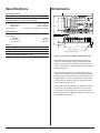
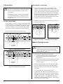
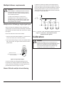
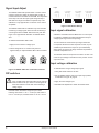
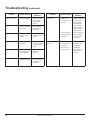
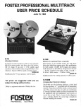
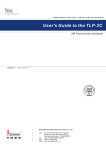
PROCESS CONTROL MODULE GS4
User’s Manual
GS4
Contents
Safety Warnings
Safety Warnings . . . . . . . . . . . . . . . . . . . . . . . . . . . . . . . . . . . . 2
Specifications . . . . . . . . . . . . . . . . . . . . . . . . . . . . . . . . . . . . . . 3
SHOCK
HAZARD
AVOID
HEAT
KEEP
DRY
Dimensions . . . . . . . . . . . . . . . . . . . . . . . . . . . . . . . . . . . . . . . . 3
AVOID
VIBRATION
Introduction . . . . . . . . . . . . . . . . . . . . . . . . . . . . . . . . . . . . . . . . 3
Installation . . . . . . . . . . . . . . . . . . . . . . . . . . . . . . . . . . . . . . . . . 4
• This symbol
denotes an important safety tip or warning.
Please read these instructions carefully before performing any
of the procedures contained in this manual.
• DO NOT INSTALL, REMOVE, OR REWIRE THIS
EQUIPMENT WITH POWER APPLIED. Have a qualified
electrical technician install, adjust and service this equipment.
Follow the National Electrical Code and all other applicable
electrical and safety codes, including the provisions of the
Occupational Safety and Health Act (OSHA), when installing
equipment.
• Reduce the chance of an electrical fire, shock, or explosion by
proper grounding, over-current protection, thermal protection,
and enclosure. Follow sound maintenance procedures.
Mounting . . . . . . . . . . . . . . . . . . . . . . . . . . . . . . . . . . . . . . . . . 4
Wiring . . . . . . . . . . . . . . . . . . . . . . . . . . . . . . . . . . . . . . . . . . . 4
Shielding guidelines . . . . . . . . . . . . . . . . . . . . . . . . . . . . . . . 4
Screw terminal block . . . . . . . . . . . . . . . . . . . . . . . . . . . . . . . . 4
Connections . . . . . . . . . . . . . . . . . . . . . . . . . . . . . . . . . . . . . . . 5
AC line connections . . . . . . . . . . . . . . . . . . . . . . . . . . . . . . . 5
Input signal connections . . . . . . . . . . . . . . . . . . . . . . . . . . . . 6
Master signal generator . . . . . . . . . . . . . . . . . . . . . . . . . . . . 5, 6
Output voltage connections . . . . . . . . . . . . . . . . . . . . . . . . . . . 7
Multiple follower requirements . . . . . . . . . . . . . . . . . . . . . . . . . 7
Multiple drives following a single signal input . . . . . . . . . . . . 7
Master GS4 with multiple drives following . . . . . . . . . . . . . . 7
Calibration . . . . . . . . . . . . . . . . . . . . . . . . . . . . . . . . . . . . . . . . . 8
Signal Input Adjust . . . . . . . . . . . . . . . . . . . . . . . . . . . . . . . . 8
WARNING
Circuit potentials are at 120 VAC or 240 VAC above
earth ground. Avoid direct contact with the printed
circuit board or with circuit elements to prevent the
risk of serious injury or fatality. Use a non-metallic
screwdriver for adjusting the calibration trimpots.
Use approved personal protective equipment and
insulated tools if working on this drive with power
applied.
DIP switches . . . . . . . . . . . . . . . . . . . . . . . . . . . . . . . . . . . . . 8
Input signal calibration . . . . . . . . . . . . . . . . . . . . . . . . . . . . . 8
Input voltage calibration . . . . . . . . . . . . . . . . . . . . . . . . . . . . 9
Input current calibration . . . . . . . . . . . . . . . . . . . . . . . . . . . . 9
Troubleshooting . . . . . . . . . . . . . . . . . . . . . . . . . . . . . . . . . . . . 9
Before troubleshooting . . . . . . . . . . . . . . . . . . . . . . . . . . . . . 9
Illustrations
Figure 1. Process Control Module (GS4) Dimensions . . . . . . . . 3
Figure 2. Screw Terminal Block. . . . . . . . . . . . . . . . . . . . . . . . . . 4
Figure 3. 115 VAC Power Connection. . . . . . . . . . . . . . . . . . . . . 5
Figure 4. 230 VAC Power Connection. . . . . . . . . . . . . . . . . . . . . 5
Figure 5. Connection – Following an External Signal. . . . . . . . . 5
Figure 6. Unidirectional Manual Master
Signal Source Connection . . . . . . . . . . . . . . . . . . . . . . . . . . . . 6
Figure 7. Bidirectional Manual Master
Signal Source Connection . . . . . . . . . . . . . . . . . . . . . . . . . . . . 6
Figure 8. Connection – Output Voltage. . . . . . . . . . . . . . . . . . . . 6
Figure 9. Connection – Multiple Follower System. . . . . . . . . . . . 7
Figure 10. Signal Input Adjust. . . . . . . . . . . . . . . . . . . . . . . . . . . 7
Figure 11. Connection – Ratio Potentiometers Multiple
Follower System. . . . . . . . . . . . . . . . . . . . . . . . . . . . . . . . . . . . 7
Figure 12. SIGNAL INPUT ADJ - Calibration Positions. . . . . . . . 8
Figure 13. DIP Switch Settings. . . . . . . . . . . . . . . . . . . . . . . . . . 8
2
GoldSpec™ User’s Manual
2
Specifications
Dimensions
Dimensions
Power Requirements
IC501
C502
Input Signal Ranges (input circuit is isolated)
C507
IC502
1.93 [49]
IC503
SIGNAL
INPUT ADJ INP
P502 P503
TB502
1 2 3
–25 to +25 VDC
–250 to +250 VDC
1–5 mADC, 4–20 mADC, 10–50 mADC
C503
IC504
2.70 [69]
SW501
1
P501
TB501
Input Impedance
Voltage signal Current signal
1–5 mADC 4–20 mADC 10–50 mADC R
R501
Voltage signal
Narrow range Wide range Current signal C506
1
2
C501
C504
-1
5
+15
COM
INPUT 1
6
7
8
INPUT 2
9
0-± 10VDC OUTPUT
MODEL GCM4
GS4
120/240 VAC
2.1 WATTS
T501
IC506
120/240 VAC, 50/60 Hz, single phase
1-5MA
4-20MA
10-50MA
Line input 4.83 [123]
C505
TP
10
>25K ohms
1K ohm
235 ohms
100 ohms
1.30 [33]
Output
Impedance Voltage range, max Linearity 0.35 [9]
800 ohms
–10 to +10 VDC
4.22 [107]
4x 0.25 [6] STANDOFF
USE #8 PANHEAD SCREWS
0.01%
Operating Temperature Range 0 – 50 °C
DIMENSIONS
IN INCHES
[MILLIMETERS]
FigureALL
1. Process
Control
Module
(GS4) Dimensions
Model
GS4
a grounded
or(PCM4)
floating,Dimensions
bipolar, DC
Figure
1. accepts
Process Control
Module
signal input and generates a proportional isolated output
voltage. The output of the GS4 follows the variations of its
input: it increases as the signal increases and decreases as
the signal decreases.
This output can be supplied to the speed setting circuit of
a motor drive to rotate the motor at a speed proportional to
the signal input. Because the GS4 can follow bipolar input
voltage signals, it can drive a regenerative variable speed
drive through the complete range of motor speeds in both
forward and reverse directions.
This manual contains specifications, installation procedures,
connections, and calibration procedures for the process
control module, model GS4. Refer to your variable speed
drive user’s manual for additional installation, operation, and
troubleshooting procedures.
GS4
3
Installation
Shielding guidelines
WARNING
WARNING
Do not install, rewire, or remove this control with
input power applied. Doing so may cause fire
or serious injury. Make sure you have read and
understood the Safety Warnings before attempting
installation.
Mounting
• GS4 components are sensitive to electrostatic fields.
Avoid contact with the circuit board directly.
• Protect the GS4 from dirt, moisture, and accidental
contact. Provide sufficient room for access to the terminal
block.
• Mount the GS4 away from other heat sources. Operate
within the specified ambient operating temperature range.
The operating temperature range for the GS4 is 0°C
50°C.8:35 AM Page 22
0-0152r6.qxp through
3/30/2006
22
• Prevent loose connections by avoiding excessive vibration
of the process control module board.
Calibration
Signal Input Adjust
• Mount the GS4 in either a horizontal or vertical plane.
• The GS4 is mounted using 4 – 0.25 inch [6mm] standoffs.
See INPUT
Figure ADJ
1, page
3 for the physical
The SIGNAL
potentiometer
is used tolocations
set the of these
standoffs.
Use
#8
panhead
screws
to
fasten
maximum Test Point voltage to approximately 5 VDC, as the standoffs
the mounting
measured to
between
terminalssurface.
TP and COM. The importance of this
step is to scale the input signal voltage to keep it well within the
range of the PCM4’s comparator chip. This calibration is only
Wiring
approximate. A tolerance of 0.2 Volts is acceptable.
Under no circumstances should power and logic
leads be bundled together. Induced voltage can
cause unpredictable behavior any electronic device.
As a general rule, manufacturer recommends shielding of all
conductors.
If it is not practical to shield power conductors, manufacturer
recommends shielding all logic-level leads. If shielding of
logic level leads is not practical, the user should twist all
logic leads with themselves to minimize induced noise.
It may be necessary to earth ground the shielded cable. Do
not ground both ends of the shield.
If the drive continues to pick up noise after grounding the
shield, it may be necessary to add AC line filtering devices,
or to mount the drive in a less noisy environment.
Logic wires from other input devices, such as motion
controllers and PLL velocity controllers, must be separated
from power lines in the same manner as the logic I/O on the
7
Installation
GS4.
Screw terminal block
Screw terminal block
Connections to Minarik’s PCM4 are made to a screw terminal
Connections
the GoldSpec™’s
GS4 areblock
made
to acounterscrew
block. Using ato
screwdriver,
turn the terminal
screw
terminal
block.
Using
a
screwdriver,
turn
the
terminal
block
clockwise to open the wire clamp. Insert stripped wire into the
screw
counterclockwise
to open
wire
clamp. Insert
wire clamp.
Turn the terminal
blockthe
screw
clockwise
to clamp the
stripped
wire
into
the
wire
clamp.
Turn
the
terminal block
wire. See Figure 2.
screw clockwise to clamp the wire. See Figure 2.
The SIGNALWARNING
INPUT ADJ is calibrated only when the PCM4 is
following a voltage
When
the PCM4
is following
a current with
Do notsignal.
install,
remove,
or rewire
this equipment
signal set the power
SIGNAL
INPUTFailure
ADJ fully
CW. See
12 may
for
applied.
to heed
thisFigure
warning
result in fire,
explosion,
or serious
approximate calibration
of SIGNAL
INPUT
ADJ. injury.
Circuit
potentials
at 120 or 240 VAC above
To calibrate the
SIGNAL
INPUTare
ADJ:
ground. To prevent the risk of injury or fatality, avoid
direct
contactvoltage
with the
printed circuit board or with
1. Apply the true
maximum
input.
circuit elements.
2. Check
at TPAWG
vs. COM
that
it is approximately
• voltage
Use 18-24
wire to
forverify
signal
wiring.
Use 16-18 AWG
5V. Adjust
SIGNAL
INPUT
ADJ
if
needed.
wire for AC line (L1, L2) wiring.
Figure
Block
Figure2.2.Screw
ScrewTerminal
Terminal Block
0 - 5 VDC
0 - 10 VDC
0 - 25 VDC
0 - 250 VDC
Figure 12. SIGNAL INPUT ADJ - Calibration Positions
4
GoldSpec™ User’s Manual
10
Input
signal
connections
Input signal
connections
Connections
Connect
theincoming
incoming
voltage
or current
signal
Connect the
voltage
or current
signal
leadsleads
to
to
INPUT
1
(terminal
8)
and
to
COM
(terminal
the
INPUT 1 (terminal 8) and to COM (terminal 7). If 7).
theIfmaximum
maximum
input
voltage
will
exceed
25V,
connect
the
signal
input voltage will exceed 25V, connect the signal leads to INPUT
leads
to
INPUT
2
(terminal
9)
and
to
COM
(terminal
7).
2 (terminal 9) and to COM (terminal 7). See Figure 5 below. See
Figure
5 below.
Use insulated
shielded
or twisted
pair
Use insulated
shielded
wire or twisted
pair wire
for PCM4
input and
for
GS4
input
and
output
signal
leads
longer
than
18
inches.
output signal leads longer than 18 inches. Connect the shielding
Connect
the shielding
earthfrom
ground
at the and
endtrim
away
to earth ground
at the endtoaway
the PCM4
the
from
the
GS4
and
trim
the
exposed
shielding
at
the
GS4 to
exposed shielding at the PCM4 to preclude accidental grounding
preclude
accidental grounding of the GS4.
of the PCM4.
WARNING
Do not connect this equipment with power applied.
Failure to heed this directive may result in fire or
serious injury.
Manufacturer strongly recommends the installation
of a master power switch in the voltage input line.
The switch contacts should be rated at 2 amps AC
and 250 volts
Bundle
thesignal-carrying
signal-carrying
leads
separately
the motor
Bundle the
leads
separately
fromfrom
the motor
leads
leads
or
AC
power
leads.
or AC power leads.
Installation
Installation
Connect the AC power leads to terminals 1 and 4.
SW501
SW501
P501
P501
C504
C504
1
1
4
4
AC POWER
AC
POWER
115
VAC
115 VAC
P501
C504
9
9
+15
+15
COM
COM
INPUT 1
INPUT 1
5
5
6
6
7
7
8
8
AC POWER
AC
230POWER
VAC
230 VAC
8
9
R
TP
-15
+15
10
5
6
SIG (+)
COM
7
COM (-)
INPUT 1
8
TP
9
10
SIG (+)
VOLTAGE SIGNAL RANGE
0 - ±250VDC
Master signal generator
-15
-15
4
4
7
INPUT 2
Figure
5. Connection––Following
Following an
Signal
Figure
5. Connection
anExternal
External
Signal
9
9
WARNING
Bidirectional output mode should never be used with
standard SCR (single quadrant) variable speed
drives. These drives only respond to one polarity in
their speed setting circuits.
R
1
1
6
INPUT 1
CURRENT SIGNAL RANGES
1 - 5mA
4 - 20mA
10 - 50mA
INPUT 2
INPUT 2
Figure 3. 115 VAC Power Connection
TB501
TB501
5
R
COM
VOLTAGE SIGNAL RANGE
0 - ±25VDC
R
Figure3.3.115
115VAC
VACPower
Power Connection
Figure
Connection
C504
C504
+15
COM (-)
R
-15
-15
-15
1
When operating on 120 VAC, leave the jumper bars installed
between terminals 1 and 2 and between 3 and 4 (see Figure
3). This is how the unit is shipped from the factory. When
operating on 230VAC, remove both jumper bars and place
one jumper bar between terminals 2 and 3 (see Figure 4).
1
AC line connections
TB501
TB501
Installation
5
5
+15
+15
6
6
COM
COM
7
7
INPUT 1
INPUT 1
8
8
R
INPUT 2
INPUT 2
The GS4 can be used as a master controller to:
(1) provide a isolated DC master voltage input to other GS4 modules interfacing with standard variable speed drives or
(2) to drive several variable speed drives directly, provided that their circuit design permits wiring of their speed circuits in common.
9
9
Unidirectional applications require a positive GS4 output.
Connect a 10K ohm potentiometer (not provided with the
GS4) as the master control pot using the +15 VDC supply
on the GS4.
Figure 4. 230 VAC Power Connection
Figure 4. 230 VAC Power Connection
Figure 4. 230 VAC Power Connection
The normal wiring of an external master control
potentiometer is the CW side of the potentiometer to +15 V
supply (terminal 6), and the CCW side to COM (terminal 7).
The potentiometer wiper is connected to INPUT 1 (terminal
8). See Figure 6 (page 6) . The potentiometer is rotated
clockwise to increase the voltage at INPUT 1 and, therefore,
increasing the GS4 output voltage.
GS4
5
Installation (continued)
Output voltage connections
WARNING
Bipolar input is necessary to control motor reversals when
the motor is being driven by a four quadrant, regenerative
variable speed drive.
To wire the external master control potentiometer to
provide a bipolar, adjustable voltage input signal, wire the
potentiometer across the –15 and +15V supply terminals,
with the CW end at +15V. Connect the pot wiper to the
INPUT 1 (terminal 8). See Figure 7 (page 6).
Always check the instruction manual supplied with
the variable speed drive that will be interfaced with
the GS4 module. The scheme shown for wiring to an
external voltage source, as well as the specifications
on that input, must be well understood before
proceeding.
Output connections are made to the small terminal block
on the board (TB502). Connect the output leads to terminal
1 and 2 (Figure 8). When the input signal at INPUT1 is
positive with respect to COM terminal 2 will be positive.
The center position of the wiper produces zero input
voltage. Potentiometer rotation CW from center produces
The exception to this polarity rule occurs when the GS4
increasing positive voltage; CCW rotation from center
250-0152r6.qxp
3/30/2006
Page
16 follower.
13
Installation
has
been calibrated to8:35
bias its AM
output as
a voltage
produces increasing negative voltage.
An input of zero volts can be calibrated to produce a finite
-15
+15
COM
INPUT 1
INPUT 2
T
C504
positive or negative output voltage.
5
10K OHM
SPEED ADJUST
POTENTIOMETER
(NOT PROVIDED)
1
6
7
8
6
7
8
16
INPUT 2
9
1
9
1
CW
Master Signal Source Connection
Figure 6. Unidirectional Manual Master
Signal
Source
-15 Connection
+15
COM
INPUT 1
INPUT 2
C504
Figure 6. Unidirectional Manual Master Signal Source Connection
-15
C504
1
10K OHM
SPEED ADJUST
POTENTIOMETER
(NOT PROVIDED)
Figure
10K OHM
SPEED ADJUST
POTENTIOMETER
7.(NOT
Bidirectional
PROVIDED)
T
+15
COM
INPUT 1
INPUT 2
XL/XLT
PCM 4
Most GoldSpec™
SCR–type, non-regenerative
drives
SERIES DRIVE
TB502
are designed
with the speed setting voltage positive with
0 - +5 VDC OUTPUT
respect to board common. The positive external
signal
S2
is brought to the “speed pot wiper” terminal, usually
S1to the “speed
designated S2, and the common signal lead
pot CCW’ terminal usually S1.
T
6
7
8
9
1
5
6
7
8
9
1
MM20000
GS23000C
PCM
GS44
TB502
T
5
-
The GS4 output is a isolated DC voltage. It is brought into
the speed setting circuit of a variable speed drive to replace
Installation
the main speed adjust potentiometer.
1
Figure 6.
10K OHM
SPEED ADJUST
POTENTIOMETER
Unidirectional
Manual
(NOT PROVIDED)
CW
INPUT 1
2
5
COM
2
+15
0 - +2.8 VDC OUTPUT
SERIES DRIVE
S2
S1
Figure 8. Connection – Output Voltage
Installation 17
RG51UA / MMRG
PCM 4
+
Manual Master Signal Source Connection
TB502
2
-15
C504
13
1
Installation
+
0 - ±10 VDC OUTPUT
S2
S0
1
Figure 7. Bidirectional Manual Master Signal Source Connection
PCM 4
TB502
2
Figure 7. Bidirectional Manual Master Signal Source
Connection
Series Drives
RG300 / RG400 / RG500
Series Drives
0 - ±10 VDC OUTPUT
S2
1
RB1
0 - ±10 VDC OUTPUT
RG60 / MMRGD
Series Drives
S2
RB1
GoldSpec™ User’s Manual
1
6
2
PCM 4
TB502
ratioing pot to the input signal source potentiometer as shown in
Figure 11 below.
Master PCM4 with multiple drives following
Multiple follower requirements
If a GS4 is to provide the master input voltage signal as
If a PCM4
to provide
the master
inputare
voltage
signal
as
detailed
onispage
6, dedicated
GS4’s
again
necessary.
detailed
14must
- 15, dedicated
PCM4s
are againon
necessary.
Each
of on
thepages
GS4’s
be modified
as detailed
page 19.
Each of the
PCM4s must bemay
modified
as detailed
on page
Ratioing
potentiometers
then be
wired with
their19.
CW
Ratioing
potentiometers
maymaster
then beGS4
wired
with
their
CW sides
sides
to terminal
2 of the
and
their
CCW
sidesto
terminal
2 of1 the
master
PCM4
and their CCW sides to terminal 1
to
terminal
of the
master
GS4.
of the master PCM4.
WARNING
Most GoldSpec™ variable speed drives cannot be
wired with their speed-setting circuits in common
with each other. They require a dedicated GS4 for
each variable speed drive.
Included are all GoldSpec™ models in the
GS23000C series, and all regenerative drives
(GS 6OU series). A multiple follower system using
any of these drives must consist of a master GS4
driving follower GS4 modules.
Installation
+
MASTER
INPUT SIGNAL
POTENTIOMETER
19
50K
Multiple drives following a single signal input
Multiple
drives following a single signal input
50K
-
When more that one Minarik drive must follow one voltage
When more than one GoldSpec™ drive must follow one
signal, each must be wired individually to dedicated PCM4
voltage signal, each must be wired individually to dedicated
modules. Each PCM4 module then receives the “master” input
GS4 modules. Each GS4 module then receives the “master”
signal. The MM30000 series discussed in the preceding
input signal.
paragraphs is the only exception.
7
10
PCM4
GS4
#1
7
10
PCM4
GS4
#2
7
10
PCM4
GS4
#3
Figure 11. Connection – Ratio Potentiometers Multiple Follower System
Figure 11. Connection – Ratio Potentiometers
Multiple Follower System
Each of the GS4 units must first be modified.
Each of the PCM4 units must first be modified.
1.Check that all 3 DIP switches (SW501) , located near the
1. Check that all 3 DIP switches (SW501) , located near the
center of the board, are in their OFF position.
center of the board, are in their OFF position.
Calibration
2.Cut the left hand (CCW) pin of P501, the SIGNAL INPUT
2. ADJ,
Cut the
hand
(CCW)
of P501,
theshows
SIGNAL
offleft
each
GS4.
Thepin
figure
below
thisINPUT
trimmer
ADJ,
off
each
PCM4.
The
figure
below
shows
this
trimmer
potentiometer.
potentiometer.
WARNING
Dangerous voltages exist on the GS4 when it is
powered. If the trimpots must be adjusted with power
applied, use insulated tools and the appropriate
personal protectionequipment. BE ALERT. High
voltages can cause serious or fatal injury.
SIGNAL
INPUT ADJ
CUT AND REMOVE LEFT PIN OF
THE SIGNAL INPUT ADJ TRIMPOT
ON EACH PCM4 BOARD
50K
P501
Figure 10. Signal Input Adjust
Figure 10. Signal Input Adjust
Connect one 50K ohm ratioing potentiometer across
the master input voltage signal for each dedicated GS4
module. Wire each ratioing pot to the input signal source
potentiometer as shown in Figure 11 below.
Master GS4 with multiple drives following
GS4
7
As a general rule, 3/30/2006
Minarik recommends
shielding
250-0152r6.qxp
8:35 AM
Page of
22all
Each DIP switch selects the range for input current following.
DIP switch 1 is for 1 – 5 mA input, DIP switch 2 is for
4 – 20 mA input, and DIP switch 3 is for 10 – 50 mA input.
input.
To calibrate the SIGNAL INPUT ADJ:
To calibrate the SIGNAL INPUT ADJ:
1.Apply the true maximum voltage input.
1. Apply the true maximum voltage input.
2.Check voltage at TP vs. COM to verify that it is
2. approximately
Check voltage at5V.
TPAdjust
vs. COM
to verify
that it ADJ
is approximately
SIGNAL
INPUT
if needed.
5V. Adjust SIGNAL INPUT ADJ if needed.
ON
Installation
10 - 50 mA CURRENT
SIGNAL INPUT
10 - 50 MA
10 - 50 MA
4 - 20 mA CURRENT
SIGNAL INPUT
4 - 20 MA
10 - 50 MA
4 - 20 MA
10 - 50 MA
SW501
SW501
SW501
1 - 5 MA
Figure 13. DIP Switch Settings
Input signal calibration
Calibration of the MIN OUT and MAX OUT 15–turn trimpots
is required to establish the relationship between the input
voltage signal range and the output range.
The true maximum and minimum input signal values are
not required. Because the GS4 response is linear, any two
calibration points define the output vs. input relationship.
Select points as close to the range extremes as possible to
minimize extrapolation error.
The absolute maximum output from the GS4 is 10 VDC. The
Figure 2. Screw Terminal Block
minimum input voltage to the GS4 that can produce 10 VDC
output is 5 VDC.
0 - 5 VDC
0 - 10 VDC
0 - 25 VDC
0 - 250 VDC
Figure 12. SIGNAL INPUT ADJ - Calibration Positions
Figure 12. SIGNAL INUT ADJ - Calibration Postiions
Input voltage calibration
To calibrate when using a voltage input signal:
1.Verify that all DIP switches are OFF.
DIP switches
2.Set the SIGNAL INPUT ADJ to the input range position,
as indicated on Figure 12, page 8.
WARNING
Only one DIP switch should be ON at a time and only
when the GS4 is set up to follow a current signal. All
three DIP switches must be OFF when following a
voltage signal.
3.Apply the lower voltage input.
4.Set MIN OUT adjustment to obtain the desired lower
Each DIP switch selects the range for input current
following. DIP switch 1 is for 1 – 5 mA input, DIP switch 2
is for 4 – 20 mA input, and DIP switch 3 is for 10 – 50 mA
8
GoldSpec™ User’s Manual
7
Connections to Minarik’s PCM4 are made to a screw terminal
block. Using a screwdriver, turn the terminal block screw counterON to open the wire
ON clamp. Insert stripped
ON
clockwise
wire into the
wire clamp. Turn the terminal block screw clockwise to clamp the
wire. Figure
See Figure
13. 2.
DIP Switch Settings
1 - 5 MA
4 - 20 MA
SW501
1 - 5 mA CURRENT
SIGNAL INPUT
4 - 20 MA
Screw terminal block
VOLTAGE
SIGNAL INPUT
1 - 5 MA
Input
Adjust
If Signal
it is not practical
to shield
power conductors, Minarik
22
Calibration
recommends
shielding all logic-level leads. If shielding of logic
level leads
not practical,
theADJ
user should
twist all logic
leads
TheisSIGNAL
INPUT
potentiometer
is used
to set the
Signal
Input
Adjust
with themselves
to
minimize
induced
noise.
maximum Test Point voltage to approximately 5 VDC, as
measured between terminals TP and COM. The importance
The SIGNAL INPUT ADJ potentiometer is used to set the
It may be
necessary
toto
earth
ground
the shielded
of this
step is
scale
the input
signal cable.
voltageDo
tonot
keep it
maximum Test Point voltage to approximately 5 VDC, as
ground well
bothwithin
ends ofthe
therange
shield.of the GS4’s comparator chip. This
measured between terminals TP and COM. The importance of this
calibration is only approximate. A tolerance of 0.2 Volts is
step is to scale the input signal voltage to keep it well within the
If the drive
continues to pick up noise after grounding the shield,
acceptable.
range of the PCM4’s comparator chip. This calibration is only
it may be necessary to add AC line filtering devices, or to mount
approximate. A tolerance of 0.2 Volts is acceptable.
the drive
in aSIGNAL
less noisy
environment.
The
INPUT
ADJ is calibrated only when the GS4
is following a voltage signal. When the GS4 is following a
The SIGNAL INPUT ADJ is calibrated only when the PCM4 is
Logic wires
from
otherset
input
such
as motion
current
signal
thedevices,
SIGNAL
INPUT
ADJcontrollers
fully CW. See
following a voltage signal. When the PCM4 is following a current
and PLL
velocity
controllers,
must
be
separated
from
power lines
Figure 12 for approximate calibration of SIGNAL
INPUT
signal set the SIGNAL INPUT ADJ fully CW. See Figure 12 for
in the same
ADJ.manner as the logic I/O on the PCM4.
approximate calibration of SIGNAL INPUT ADJ.
1 - 5 MA
conductors.
2.Disconnect AC line voltage from the GS4 and variable
speed drive.
voltage output.
5.Apply the higher voltage input.
3.Check the GS4 and drive closely for damaged
components.
6.Set MAX out adjustment to obtain the desired higher
voltage output.
7.Apply the true maximum input voltage.
4.Check that no conductive or other foreign material has
become lodged on the printed circuit board.
8.Check voltage at TP vs. COM to ensure that it is
approximately 5VDC at the maximum input voltage.
Adjust SIGNAL INPUT ADJ if necessary.
5.Verify that every connection is correct and in good
condition.
9.Repeat steps 3 – 6 until no further recalibration is needed.
6.Verify that there are no short circuits or grounded
connections.
Input current calibration
7.Check that the input voltage jumpers are installed
properly for the input voltage being used (see page 4).
To calibrate when using a current input signal:
8.Check that the drive’s rated armature and field outputs are
consistent with the motor ratings.
1.Verify that the correct DIP switch is ON and that the
others are in the OFF position.
2.Set the SIGNAL INPUT ADJ fully CW.
3.Apply the lower current input.
4.Set MIN OUT adjustment to obtain the desired lower
voltage output.
5.Apply the higher current input.
6.Set MAX OUT adjustment to obtain the desired higher
voltage output.
7.Repeat steps 3 – 6 until no further recalibration is
necessary.
Troubleshooting
WARNING
Dangerous voltages exist on the GS4 when it is
powered. High voltages can cause serious or fatal
injury.
Before troubleshooting
1.Perform the following steps before starting any procedure
in this section:
GS4
9
Troubleshooting (continued)
Suggested
Solutions
Problem
Possible Causes
Motor attached to the
drive does not run.
1.No output voltage
from GS4 (TB502).
1. Recalibrate the
GS4. If there is still
no output send
GS4 to Applied®
for repair.
2.Loose connections
between GS4 and
motor drive.
2.Check connections
between TB502
and the input of
motor drive.
3.GS4 is not
receiving AC line
voltage.
3.Apply AC line
voltage to terminals
1and 4.
4.Input signal is not
connected.
4.Check that the GS4
is receiving voltage
(or current) input
signal.
10
5.SIGNAL INPUT
ADJ potentiometer
is not calibrated.
5.Calibrate SIGNAL
INPUT ADJ
(page 9)
6.Motor drive not
calibrated properly.
6.Re-calibrate motor
drive according to
manufacturer’s
instructions.
Problem
Motor is not running
at full speed.
Motor runs too slow,
or too fast.
GoldSpec™ User’s Manual
Possible Causes
Suggested
Solutions
1.Voltage out
(TB502) is not
changing as input
changes
1.Check that the
voltage out (TB502)
is changing as
input changes.
Recalibrate the
GS4. If voltage is
still not changing
send the drive to
Applied® repair.
2.Loose connections
between GS4 and
motor drive
2.Check connections
between TB502
and the input of
motor drive.
1.DIP switches are
not set properly for
current input
1.Check DIP switch
positions if using
current input.
2.Motor drive not
properly working
2.Re-calibrate
motor according
manufacturer’s
instruction
NOTES
GS4
11
Corporate Headquarters
1 Applied Plaza, Cleveland, Ohio 44115
Toll Free Phone: 1-877-279-2799
Applied.com
© 2009 Applied Industrial Technologies, Inc. All Rights Reserved. C-0609-11-5448
GoldSpec™ is a registered trademark of Applied Industrial Technologies.
GoldSpec™ User’s Manual