1
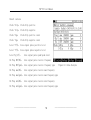
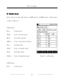
User's Guide to the TLP-3C
2M Transmission Analyzer
TLP-3C
English Version
Shanghai Grandway Telecom. Tech. Co., Ltd.
6F,Xin'an Building No. 99 Tianzhou
Road New-tech Developing Zone
Caohejing Shanghai, China(200023)
+86-21-54451260/61/62/63
Tel:
Fax: +86-21-54451266
Web: www.grandway.com.cn
Add:
TLP-3C User Manual
1. Overview
2M Transmission Analyzer is a multi-functional and full- featured digital
transmission system test device, designed for the installation test, engineering
check and acceptance, daily maintenance of digital networks, mainly performing
channel test, alarm analysis, fault finding and signalling analysis. In addition,
this instrument further provides various protocol converters with one-way and
bi-directional bit error test function. These capabilities make it ideal for
field use.
1)
2M measurement
l 75Ω and 120Ω line interfaces
——————————————
1
——————————————
TLP-3C User Manual
l HDB3 and AMI line codes
l Out-of-service 2Mb/s, N×64kb/s BER testing
l In-service framed and unframed double-channel testing
l “PCM simulator” mode testing
l Frame data control and monitoring
l Timeslot activity monitoring, FAS, N-FAS, TS16MFO analysis
l Built-in 64kb/s tone channel listen capability
l CAS and CCS signaling generation and monitoring
l Round trip delay measurement
l APS delay measurement
l Extensive error and alarm generation
——————————————
2
——————————————
TLP-3C User Manual
l VF tone generation and measurement
l Level measurement
l Pulse mask measurement
l Clock slip measurement
l Up to ±999ppm transmit clock deviation
l Clock source: Internal, Interface or External 2M clock/signal
l Real-time transmit circuit open/short indication
2) Datacom measurement
l Datacom (V.24, V.35, V.36, X.21, RS-449, RS-485, EIA-530 and EIA-530A)
interfaces BER Testing
——————————————
3
——————————————
TLP-3C User Manual
l ASYNC BER testing with baud rate 300b/s~38..4Kb/s
l SYNC BER testing with data rate 300b/s~8Mb/s
l DTE or DCE emulation
l SYNC clock source and sense selection
l Frequency measurement
l Handshaking signals control and monitoring
3)
G.703 CO measurement
l G.703 CO 64kb/s BER testing
l Octet timing control and monitoring
Clock source: Internal, Interface selectable
——————————————
4
——————————————
TLP-3C User Manual
4)
Protocol converter measurement
l 2M-Datacom SYNC 64k or N×64kb/s BER testing
l 2M-G.703 CO SYNC 64kb/s BER testing
l Frequency and offset measurement
l Handshaking signals monitoring
l 2M frame data and alarm monitoring
5)
Other functions
l Real-time clock
l Test pattern: PRBS, Fixed Code and 16-BIT User Word
——————————————
5
——————————————
TLP-3C User Manual
l Error injection: Single and Fixed Rate
l Manual and auto-timer measurement
l ITU-T G.821, G.826, and M.2100 performance analysis
6) Optional Teting functions
Jitter measurements to ITU-T standard O.172
l
Frequency and offset measurement
——————————————
6
——————————————
TLP-3C User Manual
2. Appearance
2.1 Front Panel
① Status、Alarm LEDs
② LCD Display
③ Speaker
④ Power
⑤ Operating Key
⑥ Functional Key
⑦ Cursor Move Key
——————————————
7
——————————————
TLP-3C User Manual
Figure2.1. Front Panel
——————————————
8
——————————————
TLP-3C User Manual
2.1.1 Status,Alarm LED Indicators
As Figure 2.2, the LEDs indicate the port status of Rx1 or DATA.
The LEDs of right side indicate current status,the LEDs which light
green indicate normal conditons,and the LEDs which light red indicate
that any error or alarm conditions occur.When the event finish,the LEDs
are turned off.
The LEDs of left side indicate history record,when the event occur,the
correspond LED lights yellow even the event finish,until clear by
pressing the key CLR HIS.
Figure2.2 LEDs Indicator
LED Indicators:
POWER
Power indicator.the LED light green indicates that tester power is supplied by
——————————————
9
——————————————
TLP-3C User Manual
built-in batteries or power charger normally, light red indicates that the power is supplied
by built-in batteries and the power is low,light orange indicates that the power is supplied
by power charger and the built-in batteries is recharging.
SIGNAL
Rx1 or DATA Signal status indicator.
FRAME
Rx1 signal Frame indicator
MFRAME
Rx1 signal Multiframe indicator
CRC-4
Rx1 signal structure indicator
PATTERN
Rx1 or DATA signal Pattern indicator
AIS
Rx1 or DATA Alarm Indication Signal indicator
RA
Rx1 signal Remote Alarm indicator
MRA
Rx1 signal Multiframe Remote Alarm indicator
CODE ERR Rx1 signal Code Error indicator
FAS ERR
Rx1 signal FAS Error indicator
CRC ERR
Rx1 signal CRC Error indicator
EBIT ERR Rx1 signal EBit Error indicator
——————————————
10
——————————————
TLP-3C User Manual
PAT SLIP Rx1 or DATA signal pattern slip indicator
BIT ERR
Rx1 or DATA signal Bit Error indicator
1
2.1.2 LCD Display
LCD Display is made up of three parts, shown as
Figure 2.3
2
① Status Display
The Status Display part is at the upper side of LCD
Display,day and time is displayed at the right
side.The icons at the left side indicate the status of tester.
Figure 2.3 LCD Display
The tester power is supplied by built-in batteries,and indicate the left power of the
batteries.
The tester power is supplied by power charger.
The tester is not testing.
——————————————
11
——————————————
3
TLP-3C User Manual
The automatic test timer has been set and indicates the timer tester will start the
automatic test testing function at the specified time.
The tester is running test.
Error Code is being injected
When Code Error or Alarm is detected,the speaker will beep out a warning
Viewing saved Setting or Result record
Printing
Open Com for communication with PC
The keypad is locked,only key
pressing key
work, you can unlock the keypad by
and key
.
The screen is locked.
② Main Display
The Main Display part display test settings and results.
③
Function Key and 和
Function Extend Key Display
The Function Key Display part is at the buttom of LCD Display, every function key correspond
——————————————
12
——————————————
TLP-3C User Manual
to the function display at the Function Key Display area, the Function Extend Key extend more
function of the function key.
is shortcut functional key.
2.1.3 Speaker
Listen in the channel, the volume can be adjusted at the menu “listen”or “Audio”.
2.1.4 Keypad
The Keypad is made up of 4 parts, power key, function key, operating key and cursor move key,
shown as Figure 2.4
Figure 2.4 Keypad
——————————————
13
——————————————
TLP-3C User Manual
①
Power key
Power on or off the tester
②Operating key
Clear History, clear the alarm history.
Error Injection, inject errors when sending signal.
Set/Test switch, switch between Settings and Results interface.
Run/Stop, run testing or stop testing.
Escape key, escape to the upper interface, finally return to the main interface
Enter key, perform the F1 key function.
③Functional key
Functional Key(short for F key)。The function correspond to the Function
Key Display.
Function Extend Key, Extend the Function Key.
④Cursor Move Key
——————————————
14
——————————————
TLP-3C User Manual
Move the Cursor towards the direction.
2.2 Back Panel
� Tester Information
� Reset Hole: Reset the tester
� Carrying Case
——————————————
15
——————————————
TLP-3C User Manual
Figure 2.5 Back Panel
3 Side Panel
2.
2.3
1
2
3
Figure 2.6 Side Panel
① External Power Supply socket.
② RS232, communicating with printer or PC
③ DATACOM,can be switch to various standard interface via switch cable.
——————————————
16
——————————————
TLP-3C User Manual
2.4 Upper Panel
1
2
3
5
4
Figure 2.7
6
Upper Panel
② ④ ⑥ Unbalanced interface
——————————————
17
——————————————
TLP-3C User Manual
3. Main Interface
You can enter Main Interface by performing below operation
⑴ Power On
⑵ Press Escape Key once or more times
——————————————
18
——————————————
TLP-3C User Manual
Figure 3.1 Main Interface
3.1 Interface select
You can enter the follow interface from Main Interface:
Settings
Move the cursor to the place of Settings, press Enter into the Settings Interface. When
the cursor is at the place of Settings, you can set the Work Mode as Normal Test, or Through
Test, or Delay Test, or Audio Test, or APS Test by pressing corresponding F key.
Results`
Move the cursor to the place of Results, press Enter into the Result interface.when the
cursor is at the place of Results, you can enter the Results, TS Analysis, Listen, G.703
interface by pressing corresponding F key.
——————————————
19
——————————————
TLP-3C User Manual
FileMngr
Move the cursor to FileMngr, you can enter the SetMngr or RsltMngr interface by pressing
corresponding F key。
MeterCfg
Move the cursor to MeterCfg, you can set the configration of Display, Printset and
Datetime in this interface.
PC Connect
Move the cursor to PC Connect, press Enter or F1 to turn off the connection, press F2 to
turn on the connection, and the icon
is displayed at the Status Display.
Update
Move the cursor to Update, press Enter or F1 to enter the Update introduction interface.
——————————————
20
——————————————
TLP-3C User Manual
3.2 Shortcut
You can enter some main interface from any interface fast,additionally you can perform keypad
lock function by shortcut.
In any interface, when
is displayed at the
Function Extend Key area, press
,the left buttom
of the LCD Display will popup a shortcut menu, press
again, the menu disappear.
——————————————
21
——————————————
TLP-3C User Manual
Figure 3.2 Shortcut Menu
Move the cursor to the item in the menu, press Enter or F1 select KeyPad Lock or enter the
interface Settings, Results, SetMngr, RsltMngr or MeterCfg.
4. Settings
In this interface, you can set the test items and parameters.
——————————————
22
——————————————
TLP-3C User Manual
4.1 Tx/Rx1/DATACOM
It is the
interface of 2Mbit/s, Tx is on the left
side and Rx is on the right side, shown as Figure 4.3.
Figure 4.1 2Mbit/s
——————————————
23
——————————————
TLP-3C User Manual
It is the interface of DATACOM, Tx is on the left side
and Rx is on the right side, shown as Figure 4.2.
Figue 4.2 DATACOM
4.1.1 Interface Information
Move the cursor to InfcInfo, you can select PrePage, NxtPage or ProSet.this interface is made
up of 4 parts: Tx/Rx1/DATACOM, Clk/Rx2, OtherSet, PrintSet.
——————————————
24
——————————————
TLP-3C User Manual
4.1.2 Work Mode
Move the cursor to Work Mode,you can select the item below:
Normal Test: Normal Test is used for testing Error Code, Slip, Channel etc.
Through Test:Set the Work Mode as Through Test.
Audio Test:
Set the Work Mode as Audio Test, you can test the Frequency, Level of the TS
channel.
Delay Test:
Test 2Mbit/s, n × 64kbit/s, V interface channel for Round
trip delay
measurement.
APS Test:`
APS Test is used for testing Auto Protect Second
4.1.3(Tx)、( Rx)
Move the cursor to the Rx,you can select the item below
Rx: Tx is independent of Rx parameter, can be set individually.
Rx=Tx:
Rx parameter is same as Tx, when Tx is changed, Rx will be changed as Tx.
4.1.4 Interface Mode
——————————————
25
——————————————
TLP-3C User Manual
Move the cursor to the Interface Mode, you can select the item below. The InfcMode of Rx is
same as the one of Tx.
2Mbit/s:
Test 2Mbit/s channel
Codirectional 64k:Test 64kbit/s channel
V.35:
Test V.35 data channel
V.24:
Test V.24 data channel
X.21:
Test X.21 data channel
RS449:
Test RS449 data channel
4.1.5 Signal Form
Move the cursor to Signal Form at Tx side, you can set item value below:
Unframed:
Unframed signal form
PCM31:
31 signal form
PCM31CRC:
31 signal form with CRC-4
PCM30:
30 signal form, TS 16 transmit code
PCM30CRC:
30 signal form, TS 16 transmit code with CRC-4
——————————————
26
——————————————
TLP-3C User Manual
4.1.6 DATA Port
Move the curor to Data Port, you can select the item below:
G.703(75Ω):
75Ω unbalanced interface.
G.703(120Ω):
120Ωbalanced interface.
4.1.7 Clock Mode
Move the curor to the Clock Mode, you can select the item below:
Internal Clock:
Clock source is from Internal Clock.
Clock Derived :
Clock source is the clock derived form input signal.
External Clock:
Clock source is from External Clock. External Clock signal is 2.048MHz or
2.048Mbit/s.
4.1.8 Pattern
Move the curor to the Pattern of Tx, you can select the item below:
——————————————
27
——————————————
TLP-3C User Manual
2e9-1:
Set Pattern as 2e9-1. As ITU—T0.151 define.
2e11-1: Set Pattern as 2e11-1.
2e15-1: Set Pattern as 2e15-1.。
WORD:
Set Pattern as 8bit code. When select the item WORD, the function of F1 is set 1, and
the function of F2 is set 0. press
or
to move cursor, press F key to set value.
Online Test: It is used for 2Mbit/s Error Code Online Test, and Bit Error、Pattern Slip and
Pattern Loss Test are unavailable.
4.1.9 Pattern Porality
Move the cursor to Pattern Porality, you can select the item below
Codirectional:
The Pattern direction is codirectional as ITU—T0.151 defined.
Inverted:
The Pattern direction is inverted as ITU—T0.151 defined.
——————————————
28
——————————————
TLP-3C User Manual
4.1.10 Wave Form
Move the cursor to Wave Form, you can select the item below
HDB3:
Input signal line code is HDB3.
AMI:
Input signal line code is AMI.
4.1.11 Time Slot Select
Move the cursor to TS Select, you can select the item
below
All TS: Press F2 to select All TS.
it will set 30 timeslot as test channel while signal
form is PCM30CRC or PCM30;
it will set 31 timeslot as test channel while signal
form is PCM31CRC or PCM31.
Figure 4.7 TS Settings
——————————————
29
——————————————
TLP-3C User Manual
n*64k:
Press F1 to select n*64k, choose any timeslot as test channel.
Perform n*64k select function to enter TS Config interface
shown as Figure 4.7。
Set Timeslot:
Move the cursor to the timeslot you want to set, press F1 to select the timeslot, the
timeslot No. is displayed black. Press F2 to deselect the timeslot, the timeslot No. is
display white.press F3 to select all timeslots, press F4 to clear all timeslot. The pattern
will be injected into the selected timeslot.
Set Timeslot code
Move the cursor to the bit you want to set in the timeslot code, press F1 to set it 1,
press F2 to set it 0.
4.1.12 Signal Port
——————————————
30
——————————————
TLP-3C User Manual
Move the cursor to Signal Port, you can select the item below
Terminal:Signal input impedance is 75 Ω or 120Ω.
Bridge: 75Ω或 120Ω.Signal input impedance is high, more than 75 Ω or 120Ω.
Monitor: Signal input impedance is 75 Ω or 120Ω and 26 dB plus for input signal.
4.1.13 Emulation Mode
Move the cursor to Emulation Mode, you can select the item below.
DTE:Emulation DTE mode.
DCE:Emulation DCE mode.
4.1.14 Speed
Move the curor to Speed, you can select the item below:
PreSpeed:Speed decrease.
NxtSpeed:Speed increase.
4.1.15 Clock Porality
——————————————
31
——————————————
TLP-3C User Manual
Move the cursor to Clock Porality, you can select the item below:
CoDirect:Clock porality is codirectional.
Inverted:Clock porality is inverted.
4.1.16 Control Signal
Move the cursor to Control Signal, you can select the item below:
Connect:
Control signal is connected.
Disconnect:
Control signal is disconnectd.
4.2 CLK/Rx2 Settings
Clk/Rx2 setings is shown as Figure 4.8.
——————————————
32
——————————————
TLP-3C User Manual
Figure 4.8 ClK/Rx2 Settings
4.2.1 Work Mode
Move the cursor to Work Mode, you can select the item below.
——————————————
33
——————————————
TLP-3C User Manual
Clock Input: Clk/Rx2 port is set as external clock input, and the Signal Form and Wave Form
is unavailable.
2M Test:
Clk/Rx2 port is the second port to perform 2Mbit/s testing.
4.2.2 Signal Form
Move the cursor to Signal Form at Tx side, you can set item’s value below:
Unframed:
Unframed signal form
PCM31:
31 signal form
PCM31CRC:
31 signal form with CRC-4
PCM30:
30 signal form, TS 16 transmit code
PCM30CRC:
30 signal form, TS 16 transmit code with CRC-4
4.2.3 DATA Port
Move the curor to Data Port, you can select the item below:
G.703(75Ω):
75Ω unbalanced interface.
G.703(120Ω):
120Ωbalanced interface.
——————————————
34
——————————————
TLP-3C User Manual
4.2.4 Signal Port
Move the cursor to Signal Port, you can select the item below
Terminal:Signal input impedance is 75 Ω or 120Ω.
Bridge: Signal input impedance is high, more than 75 Ω or 120Ω.
4.2.5 Wave Form
Move the cursor to Wave Form, you can select the item below
HDB3:
Input signal line code is HDB3.
AMI:
Input signal line code is AMI.
——————————————
35
——————————————
TLP-3C User Manual
4.3 OtherSet
Figure 4.10 OtherSet
4.3.1 Error Code Injection
Move the cursor to Error Code Injection, you can select the item below
None:
No Error Code injection.
——————————————
36
——————————————
TLP-3C User Manual
Bit ERR: Select Bit Error injection, and the injection mode you can select Single or Speed.
the Speed range is 1×10⁻²~1×10⁻⁶.
PAT Slip:
Select PAT Slip injection, and the injection mode you can select Single.
FAS ERR:
Select
FAS
Error
injection,
and
the
injection
mode
you
can
select
single,continuous 2, continuous 3,continuous 4.
While select Error injection, if the injection mode is single, or continuous 2, or continuous
3, continuous 4, then press Key ERR INJ once, 1, or 2, or 3, or 4 Error Codes will be
injected, and the icon
is displayed for 0.5 second, and then disappears. If the injection
mode is speed, then press Key ERR INJ once, Error Code is being injected, and the icon
being displaying. Press
Key ERR INJ again, Error Code injection stops, and the icon
disappears.
4.3.2 Alarm Injection
Move the cursor to Alarm Injection, you can select the item below.
None:
No Alarm injection
AIS:
Select AIS injection
——————————————
37
——————————————
is
TLP-3C User Manual
FAS Loss:Select FAS Loss injection
RA:
Select RA injection
MRA:
Select MRA injection
4.3.3 Timing Test
Move the cursor to Timing Test, you can select the item below
Off:
Turn off the function of Timing Test.
On:
Turn on the function of Timing Test, and the icon
When the function is on, the icon
is display at Status Area.
is display at Status Area. And when the timer is up,
test will start automatically.
4.3.4 Test Time
Move the cursor to Test Time, you can select the item below
Off:
Turn off the function of Test Time.
On:
Turn on the function of Test Time
When the function is on, and the timer is up, test will stop automatically.
——————————————
38
——————————————
TLP-3C User Manual
4.3.5 Auto Repeat
Move the cursor to Auto Repeat, you can select the item below
Off:
Turn off the function of Auto Repeat.
On:
Turn on the function of Auto Repeat.
4.4 PrintSet
Icon
means that the function is on, while icon
——————————————
39
is off, shown as Figure 4.11.
——————————————
TLP-3C User Manual
Figure 4.11 PrintSet
4.4.1 Sound Alarm
ErrCode: Tester beeps when Error Code is detected.
Alarm:
Tester beeps when Alarm is detected.
4.4.2 Print Start
Functions work when test is started.
Event:
Print start when error code or alarm event is detected.
——————————————
40
——————————————
TLP-3C User Manual
EndTest: Print start when test end.
Interval:Print start when time interval arrive.
4.4.3 Print Content
Settings:
Print content include Settings.
ErrCode:
Print content include Error Code results.
Alarm:
Print content include Alarm results.
LineAnal:
Print content include Line Analysis results.
ErrCodeAnal: Print content include all analysis results.
5. Professional Setting
At Tx/Rx1/DATACOM interface, set InfcMode as 2Mbit/s, set Signal Form of Tx not as Unframed,
——————————————
41
——————————————
TLP-3C User Manual
you can enter this ProSet.
At Settings interface, press ‘ProSet’,enter the professional setting interface.
5.1 Frame Information
Move the cursor to the bit you want to set, press F1 to set it as 1, F2 as 0, shown as Figure
5.1.
Figure 5.1 Frame Info
——————————————
42
——————————————
TLP-3C User Manual
Bits that can be set in the Frame Information list below:
Sync Frame Si: Default as 1
Async Frame Si:Default as 1
Async Frame A: Default as 0
Multi Frame Sync Frame y: Default as 0
★ Note: Incorrect setting will make error code or alarm, use default setting to test at
normal time.
5.2 Sync Information
Move the cursor to the bit you want to modify, press F1 to set it as 1, F2 as 0, F3 set all
bits in the byte as 1.
——————————————
43
——————————————
TLP-3C User Manual
Figure 5.2 Sync Info
5.3 ABCD Setting
5.3 ABCD SettingMove the cursor to the bit you want to modify, press F1 to set it as 1, F2
as 0, F3 set all bits in the byte as 1
——————————————
44
——————————————
TLP-3C User Manual
Figure 5.3 ABCD Setting
Note: every ABCD value can not be set as all 0.
——————————————
45
——————————————
TLP-3C User Manual
6. Results
6.1 Normal Test Result
Set the Work Mode in Tx/Rx1/DATA interface as Normal Test or Through Test, the result is
Normal Test Result.
6.1.1 Error Code Test Result
Error Code Test Result is shown as Figure 6.1.
①Test result info, test time
②spend time,remained time
③Test paramenter
④Test result content
——————————————
46
——————————————
TLP-3C User Manual
Test result content:
Bit ERR:
Bit Error
%Bit ERR:
Pecent of Bit Error
Code ERR:
Code Error
%Code ERR:
Pecent of Code Error
FAS ERR:
FAS Error
%FAS ERR:
Pecent of FAS Error
CRC ERR:
CRC-4 Error
%CRC ERR:
Pecent of CRC-4 Error
Ebit ERR:
Ebit Error
%Ebit ERR:
Pecent of Ebit Error
PAT Slip:
Pattern Slip
Figure 6.1 Error Code Test Result
Set the Interface Mode in Tx/Rx1/DATA interface as Datacom, the result is shown as Figure 6.2.
——————————————
47
——————————————
TLP-3C User Manual
Results content:
Bit ERR:
Bit Error
%Bit ERR:
Pecent of Bit Error
PAT Loss:
Pattern Loss
PAT Slip:
Pattern Slip
SIG Loss:
Signal Loss
Freq max:
Frequency Max
Freq min:
Frequency Min
Control Signal
Figure 6.2 Datacom Test Result
6.1.2 Alarm Test Result
Alarm Test Result is shown as Figure 6.3:
——————————————
48
——————————————
TLP-3C User Manual
Result content:
SIG Loss:
Signal Loss
AIS:
Alarm Indication Signal
FAS Loss:
FAS Loss
PAT Loss:
Pattern Loss
PWR Loss:
Power Loss
RA:
Remote Alarm
MRA:
Multiple Remote Alarm
Figure 6.3 Alarm Test Result
6.1.3 Line Analysis
The Line Analysis Results are shown as Figure 6.4.
——————————————
49
——————————————
TLP-3C User Manual
Result content:
Clock +Slip: Clock Slip positive
Clock -Slip: Clock Slip negative
Clock +Cpp:
Clock Slip positive count
Clock -Cpp:
Clock Slip negative count
Level +V(V): Line signal pulse positive level
Level -V(V): Line signal pulse negative level
Level Vp-p(V):
Line signal pulse peak-peak level
Rx Freq RCV(Hz): Line signal pulse receive frequency
Rx Freq RCV(ppm): Line signal pulse receive frequency ppm
Figure 6.4 Line Analysis
Rx Freq max(Hz): Line signal pulse receive max frequency
Rx Freq max(ppm): Line signal pulse receive max frequency ppm
Rx Freq min(Hz): Line signal pulse receive min frequency
Rx Freq min(ppm): Line signal pulse receive min frequency ppm
——————————————
50
——————————————
TLP-3C User Manual
6.1.4 Results Analysis
Results Analysis include G.821 Analysis, M.2100T Analysis, M.2100K Analysis. G.821 Analysis
is shown as Figure 6.5
G.821 Analysis:
ES(s):
Errored Second
%ES(s):
Pecent of Errored Second
SES(s):
Severe Errored Second
%SES(s):
Pecent of Severe Errored Second
AS(s):
Available Second
%AS(s):
Pecent of Available Second
UAS(s):
Unavailable Second
%UAS(s):
Pecent of Unavailable Second
Figure 6.5
G.821 Analysis
G.826 Analysis:
ES(s):
Errored Second
——————————————
51
——————————————
TLP-3C User Manual
%ES(s):
Pecent of Errored Second
SES(s):
Severe Errored Second
%SES(s):
Pecent of Severe Errored Second
AS(s):
Available Second
%AS(s):
Pecent of Available Second
UAS(s):
Unavailable Second
%UAS(s):
Pecent of Unavailable Second
BBE:
Background Block Error
%BBE:
Pecent of Background Block Error
M.2100T Analysis:
ES(s):
Errored Second
%ES(s):
Pecent of Errored Second
SES(s):
Severe Errored Second
%SES(s):
Pecent of Severe Errored Second
AS(s):
Available Second
——————————————
52
——————————————
TLP-3C User Manual
%AS(s):
Pecent of Available Second
UAS(s):
Unavailable Second
%UAS(s):
Pecent of Unavailable Second
M.2100K Analysis:
ES(s):
Errored Second
%ES(s):
Pecent of Errored Second
SES(s):
Severe Errored Second
%SES(s):
Pecent of Severe Errored Second
AS(s):
Available Second
%AS(s):
Pecent of Available Second
UAS(s):
Unavailable Second
%UAS(s):
Pecent of Unavailable Second
——————————————
53
——————————————
TLP-3C User Manual
6.2 Histogram
Set the Work Mode in Tx/Rx1/DATA interface as Normal Test or Through Test, the result can be
illustated in Histogram.
In Normal Test Results interface, press Histogram
Function Key to enter the interface, shown as Figure
6.6.
Figure 6.6
——————————————
54
Histogram
——————————————
TLP-3C User Manual
In Histogram, the horizontal axis is test time, and the vertical axis is the value of
selected event.
Error Code or Alarm type: press F1 or F2 to selct the type of Error Code or Alarm you want to
analyze.
Resolution:Minimum unit at the horizon time axis in the histogram.
Press
to increase resolution
Press
to decrease resolution
▲: Cursor
Press
Press
to move the cursor to left side by one step
to move the cursor to right side by one step
Press F3 to display the previous page content.
Press F4 to display the next page content.
Cursor information - time: the time of cursor position, or the begin time of cursor position.
——————————————
55
——————————————
TLP-3C User Manual
Cursor information - result: the error code or alarm of cursor position.
6.3 Audio Test Result
Set the Work Mode in Tx/Rx1/DATACOM interface as Audio Test, and the result will be Audio
Test result,shown as Figure 6.6.
Configurable items:
——————————————
Figure 6.6 Audio Test Result
56
——————————————
TLP-3C User Manual
Tx TS: Set the TS that used for testing Audio channel, refer to “Select TS”.
Work Mode: You can select Audio or Listen. When item Listen is selected, no audio signal is
sent out.
Tx Frequency: Set the frequency of selected timeslot signal.
Tx Level: Set the level of selected timeslot signal.
Rx TS: Set the TS that used for testing Audio channel, only one can be selected to test.
Volume control: Adjust the volume of speaker.
Test Results:
Rx Frequency:Display frequency result of the selected timeslot.
Rx Level:Display level result of the selected timeslot.
——————————————
57
——————————————
TLP-3C User Manual
6.4 Audio Listen Result
Set the Work Mode in Tx/Rx1/DATACOM interface as Audio Test, and the result will be Audio
Test result,set Work Mode in this result interface as Listen,then the result is Audio Listen
Result.shown as Figure 6.7.
Figure 6.7 Audio Listen Result
——————————————
58
——————————————
TLP-3C User Manual
Configurable items:
Rx TS: Set the TS that used for testing Audio channel, only one can be selected to test.
Volume control: Adjust the volume of speaker.
Test Results:
Rx Frequency:Display frequency result of the selected timeslot.
Rx Level:Display level result of the selected timeslot.
6.5 Delay Test Result
Set the Work Mode in Tx/Rx1/DATACOM interface as Delay Test, and the result will be Delay
Test result,shown as Figure 6.8.
——————————————
59
——————————————
TLP-3C User Manual
Figure 6.8 Delay Test Result
Press F1 ‘Start Test’to run testing. If the result is ‘SignalBad’,it means that the
performance of the test line is bad. If Delay time is more than 2.5 second, the result is
‘timeout’.
——————————————
60
——————————————
TLP-3C User Manual
6.6 APS Test Result
Set the Work Mode in Tx/Rx1/DATACOM interface as APS Test, and the result will be APS Test
result,shown as Figure 6.9.
Figure 6.9 APS Result
——————————————
61
——————————————
TLP-3C User Manual
Press F1 ‘Start Test’to run testing,when APS occur,test APS time and display the result.if
APS is more than 2.5 second, the result is ‘timeout’.press F1 again to stop the APS test.
6.7 Timeslot Analysis
Set the Work Mode in Tx/Rx1/DATA interface as Normal Test or Through Test, and the Signal
Form of Rx is not unframed, you can view Timeslot Analysis in Results.
In the Main Interface, move the cursor to Results position, press TS Analysis functional key
to enter this interface. Timeslot Analysis will not affect other ongoing test.
Timeslot Analysis results include TS Analysis, Frame Information, Sync Information, ABCD
——————————————
62
——————————————
TLP-3C User Manual
Information, shown as Figure 6.10、Figure 6.11、Figure 6.12 and Figure 6.13.
Timeslot Analysis:
TS : Timeslot No.
BIN : Binary Timeslot value
HEX : Hex Timeslot value
Figure 6.10 TS Analysis
Frame Information:
Sync Frame: c0011011, Binary format value of Sync Frame.
Async Frame:i1asssss,Binary format value of Async Frame.
——————————————
63
——————————————
TLP-3C User Manual
Multiple Sync Frame: 0000xyxx,Binary format value of Multiple Sync Frame.
Figure 6.11 Frame Information
——————————————
Figure 6.12 Sync Information
64
——————————————
TLP-3C User Manual
Figur 6.13 ABCD Information
——————————————
65
——————————————
TLP-3C User Manual
6.8 G.703 Pulse Mask
In the Main Interface, move the cursor to Reults, you
can
see
G.703
displayed
in
the
menu,
press
corresponding F key to enter G.703 interface, shown as
Figure 6.14.
Press F1 to start test, press F2 to test overshoot, F3
to undershoot.
Figure 6.14 G.703 Pulse Mask
Results:
Scope(V) : The peak level of pulse
Scope Offset:Offset between peak level of pulse and standard value
——————————————
66
——————————————
TLP-3C User Manual
Width(ns): Time of pulse’s width
Width Offset:Offset between pulse’s width and standard value.
Judgement: Judge the pulse is passed or fail.
7. FileManager
7.1 SetManager
In the interface of SetManger, Current Setting can be saved to flash, and the saved record
can be loaded at any time. Saved records are displayed with parameter as SaveNo.,test tiem
and interface mode in the table.
——————————————
67
——————————————
TLP-3C User Manual
Figure 7.1
SetMngr
7.1.1 Default Setting
Move the cursor to CurSet, press F3, will load default setting.
7.1.2 Save Current Setting
Move the cursor to CurSet, press F2, will save the current setting to flash
7.1.3 Load Setting
Move the cursor to the record, press F1 to view details, the icon
——————————————
68
is displayed at the
——————————————
TLP-3C User Manual
Status Display area under the condition. And it won’t change the current settings. If press
F2 to load the setting, the current setting is replaced.
7.1.4 Delete record
Move the cursor to the record No. you want to delete, press F3 to delete the record,press F4
to clear all records.
7.2 ResultManager
In the interface of ResultManger, Current Result can be saved to flash, and the saved record
can be viewed at any time. Saved records are displayed with parameter as SaveNo.,Test Tiem
and Interface Mode in the table.
——————————————
69
——————————————
TLP-3C User Manual
Figure 7.2
RsltMngr
7.2.1 Save Current Result
Move the cursor to current result, press F3 to save,and the current result is saved to flash
7.2.2 View Result
Move the cursor to the result No. you want to view, press F1 to view setting details, press
F2 to view result details,
7.2.3 Delete record
——————————————
70
——————————————
TLP-3C User Manual
Move the cursor to the record No. you want to delete, press F3 to delete the record,press F4
to clear all records.
★ Note: Delete the records you don’t need any more, keep more space if possible to test
much more time.
8. Meter Config
At Main Interface, move the cursor to MeterCfg, press the corresponding Functional Key to
enter this interface, shown as Figure 8.1
——————————————
71
——————————————
TLP-3C User Manual
Figure 8.1
Meter Config
8.1 Display Config
Contrast:Move the cursor to constrast position, press Functional Key to adjust the constrast.
——————————————
72
——————————————
TLP-3C User Manual
Backlight : Move the cursor to backlight position, press Functional Key to adjust the
backlight.
EverOn: The backlight is always on.
EverOff:The backlight is always off.
Timer:The backlight is lighting on lasting for the time set by timer, until time is up, press
any key the backlight light on again.
8.2 Print Config
Interface Port Mode: Series Port to connect with printer
Baudrate: set the baudrate that communicate between tester and printer
Verify: set the communication verify mode
Test Print: test the printer to see if the printer is ready
——————————————
73
——————————————
TLP-3C User Manual
8.3 Daytime Config
Config the real time clock of the tester.
——————————————
74
——————————————
TLP-3C User Manual
9. Technique Specification
TX:
● Output interface:
75 Ohm balanced, 120 Ohm balanced, conforming to G.703 requirements
● Signal structure:
Unframed
Frame (PCM30, PCM31, PCM30CRC, PCM31CRC), conforming to G.704 n×64 Kbit/s
structure
● Line code:
HDB3 or AMI
● Signal rate:
——————————————
75
——————————————
TLP-3C User Manual
2048 kbit/s
● Internal clock accuracy:
≤±10ppm
● Clocking:
Internal, external and distill
● Output intrinsic twittering:
<0.05UI(20Hz-100kHz)
● Test pattern:
False random sequence 2E6-1,2E9-1,2E11-1,2E15-1, 2E20-1, 2E23-1, conforming to
ITU-T0.151, man code 8 bit
● Free TS pattern:
8bit man mode
● Code error insertion:
FAS ERR:once, continuous twice, continuous 3 times, continuous 4 Times
BIT ERR: single 1E-2~1E-7
● Pattern slip:
——————————————
76
——————————————
TLP-3C User Manual
PAT slip
RX:
● Signal input impedance:
terminal: 75 Ohm unbalanced, 120 Ohm balanced, Tx loss conforms to G.703
bridge: >750 Ohm unbalanced, >1200 Ohm balanced
monitor:20 dB for input sensibility
● Signal input equalizing feature:
0—9 dB
● Signal input twittering capacity:
conforms to G.823
● Input anti-interference:
conforms to G.703
● Signal structure:
Unframed
——————————————
77
——————————————
TLP-3C User Manual
Frame (PCM30, PCM31, PCM30CRC, PCM31CRC), frame signal conforms to G.704 n×64
kbit/s structure
● Line code:
HDB, or AMI
● Signal rate:
2048 kbit ±50ppm
● Test pattern:
False random sequence 2E6-1,2E9-1,2E11-1,2E15-1, 2E20-1, 2E23-1, conforming to
ITU-T0.151, man code 8 bit
● Frequency test:
For line signal and voice channel signal
● Level test:
For line signal and voice channel signal
● Bit error monitoring:
FAS ERR, BIT ERR, CRC-4 code error performance test, CODE ERR
● Alarm monitoring:
——————————————
78
——————————————
TLP-3C User Manual
AIS, SIG LOSS, RA, MAR, FAS LOSS, CRC LOSS, PAT LOSS, PAT SLIP
● Slip monitoring:
PAT SLIP, CLK SLIP
● Time delay test:
Test time delay performance
● Bit error analysis:
G.821, G.826, M2100
● External clock input impedance:
Terminal:75 Ohm unbalanced, 120 Ohm balanced, Tx loss conforming to G.703
Bridge:>750 Ohm unbalanced, >1200 Ohm balanced
● External clock input signal:
HDB3/AMI conforming to G.703, pulse signal,>2.5Vp-p
——————————————
79
——————————————
TLP-3C User Manual
Technique support
Shanghai Grandway Telecom Tech. Co., Ltd
Address:6F, Xin'an Building, NO.99, Tianzhou Rd,Shanghai, P.R.China.
Tel:+86 21 54451260
Fax::+86 21 54451266
http://www.grandway.com.cn
E-mail:[email protected]
——————————————
80
——————————————