1
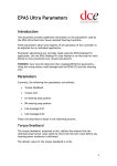
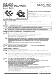
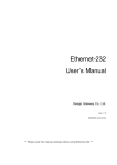
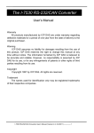
Ethernet IO
User’s Manual
Design Gateway Co., Ltd.
Rev 1.1
(PD0401-6-00-02E)
*** Please read this manual carefully before using Ethernet IO ***
Revision History
Revision
1.0
1.1
Date
5 August 2004
23 March 2005
Ethernet IO User’s Manual
Detail of change
Initial Release
Insert Quick start and edit picture.
-I-
PD0401-6-00-02E
Table of Contents
1. Introduction................................................................................................................... 1
1.1. Summary Feature................................................................................................... 1
1.2. System Requirement.............................................................................................. 2
1.3. Warranty Policy...................................................................................................... 2
2. Ethernet IO Network I/O Board ..................................................................................... 3
2.1. Ethernet IO Board Description............................................................................... 3
2.2. 10 Base-T Ethernet Module ................................................................................... 4
2.3. UART Module......................................................................................................... 4
2.4. RS485 Module ....................................................................................................... 4
2.5. RS232 Module ....................................................................................................... 5
2.6. 6 Channels Analog Input ....................................................................................... 5
2.7. 35 bits GPIO .......................................................................................................... 6
2.8. Reset Button .......................................................................................................... 8
2.9. Jumper................................................................................................................... 8
2.10. LED Indicator......................................................................................................... 9
3. Quick Start .................................................................................................................... 9
4. Configuration Application (cfg_app)........................................................................... 10
4.1. Main Control......................................................................................................... 10
4.2. Sending Data....................................................................................................... 13
4.3. Receiving Data .................................................................................................... 14
4.4. Status Bar ............................................................................................................ 14
4.5. Configuration Application Utility........................................................................... 15
Ethernet IO User’s Manual
- II -
PD0401-6-00-02E
1. Introduction
Thank you very much for purchasing Ethernet IO Network I/O Board. Please check that
all the following items are in the box. If anything is missing or damaged, contact your
distributor or Design Gateway Co.,Ltd.
- Ethernet IO Network I/O Board
- +5V Power Adapter
- CD (contents : Demo software, Library for developer, User’s Manual, Programming
Manual)
- 1.5 m Cross cable
- 1.5 m Serial cable for RS232
- User’s Manual and Programming Manual
Ethernet IO is network development board that controls user’s board via Ethernet (LAN).
It is suitable for user who not familiar with network microcontroller but would like to connect
user’s board to network. User can communicate from Ethernet IO to user’s board both
sending and receiving data or control user’s board via I/O port command such as set bit,
clear bit, set port etc. Ethernet IO provides many ports to control user’s board. General
purpose Input / Output (GPIO) is normal connection to connect to user’s board. This GPIO
supports +5V tolerant input and +2.5 V output. For long distance, user can use RS232 or
RS485 port to send or receive data from user’s board. Both RS232 and RS485 have
maximum speed at 115200 bps. Ethernet IO provides 10 bits-ADC 6 channels, 48 kHz
maximum sampling rate, to receive analog signal.
Ethernet IO set provides example application and library for Microsoft Visual C++, so
user can easily develop network system without deep knowledge of Ethernet
communication.
1.1. Summary Feature
1. Embedded network 8-bit RISC microcontroller, speed 120 MIPS
2. 10base-T Ethernet 10 Mbit Interface
Ethernet IO User’s Manual
-1-
PD0401-6-00-02E
3. 64 Kbytes flash memory
4. 16 Kbytes SRAM program memory
5. 4 Kbytes SRAM data memory
6. UART port RS232/RS485, maximum speed at 115200 bps
7. 35 bits General Purpose I/O, +5V tolerant input and +2.5V output in each pin
8. 10-bit, 6-channel ADC, 48 kHz maximum sampling rate, 2.5V reference voltage
9. 400 bytes user’s area flash memory
10. 200 Kbytes per second transfer rate in parallel mode
1.2. System Requirement
1. Windows 2000 or Windows XP
2. 10 MB of available disk space for Windows 2000 / Windows XP
3. 64 MB of available RAM for Windows 2000
4. 128 MB of available RAM for Windows XP
5. 10/100 Mbps LAN card
6. Microsoft Visual C++ 6 (for developer)
1.3. Warranty Policy
1. Product warranty is valid for 6 months from purchasing date.
2. Warranty is void if any modification has been made to this product and any incorrect
operation from this manual or warranty sticker is torn or damaged.
3. In order to claim for product exchange or technical support within warranty period,
official receipt is required for unregistered customer as an evidence of purchasing
whereas official receipt is unnecessary for registered customer (please fill up
registration card attached herewith the product and send back to Design Gateway
Co.,Ltd).
Ethernet IO User’s Manual
-2-
PD0401-6-00-02E
2. Ethernet IO Network I/O Board
Figure 2-1 Ethernet IO board
2.1. Ethernet IO Board Description
A high-level block diagram of Ethernet IO board is shown in Figure 2-2 followed by a
brief description of connector module.
LED Indicators
Jumper
10 Base-T
Ethernet
Module
UART
Module
Network
Microcontroller
RS232 Module
RS485 Module
35 Bits GPIO
Reset Button
6 channel
analog input
Figure 2-2 Block Diagram of Ethernet IO
Ethernet IO User’s Manual
-3-
PD0401-6-00-02E
2.2. 10 Base-T Ethernet Module
Ethernet IO provides 10 Base-T Ethernet Module to connect Ethernet IO with network.
Both LAN cable and cross cable can be used with Ethernet IO.
2.3. UART Module
Ethernet IO has one UART module for communication with serial mode. This UART
module has maximum speed at 115200 bps. User can select UART mode (RS232 or
RS485) by setting jumper on J8 and J11. User can not use both RS232 and RS485 at the
same time. The following table shows jumper setting for UART mode selection.
Table 2-1 RS232 and RS485 Jumper Setting
J8
UART Mode
1-2
2-3
RS232
Closed
Open
RS485
Open
Closed
J11
1-2
Closed
Open
2-3
Open
Closed
2.4. RS485 Module
Ethernet IO board provides RS485 module to connect target board with line length
greater than 1,000 meters. The following table shows RS485 interface signal
Table 2-2 RS485 Interface Signal Usage
J9 Pin #
Signal Name
Description
1
TX+
Noninverting Driver Output
2
TXInverting Driver Output
3
Gnd
Ground
4
RX+
Noninverting Receiver Input
5
RXInverting Receiver Input
Ethernet IO User’s Manual
-4-
PD0401-6-00-02E
2.5. RS232 Module
Ethernet IO board provides RS232 module for connection from Ethernet IO to PC or
user’s board. The following table shows RS232 interface signal.
Table 2-3 RS232 Interface Signal Usage
J13 Pin #
Signal Name
Description
1
TX
Transmitted data from Ethernet IO board
2
RX
Received data to Ethernet IO board
3
Gnd
Ground
2.6. 6 Channels Analog Input
Ethernet IO board provides 6 channels 10-bit analog-to-digital converters (ADCs) The
maximum sampling rate is 48 kHz and reference voltage is +2.5V. The full-scale voltage
read as 0x3FF, so the reference voltage (+2.5V) read as 0X3FE and ADCs resolution is 10
bits. The following table shows ADCs values reported at the upper and lower limits of the
ADC input voltage range and next table shows analog input connector property.
Table 2-4 ADCs Value
Analog Input Voltage
0
2.5V / 0x3FE
2.5V
2.5V + (2.5V / 0x3FE)
ADCs Value
0x000
0x001
0x3FE
0x3FF
Note : Maximum input voltage to analog pin is +2.5V.
Ethernet IO User’s Manual
-5-
PD0401-6-00-02E
Table 2-5 Analog Input Connectors
J3 Pin#
Signal Name
Description
1
AIN0
Analog input channel 0
2
AIN1
Analog input channel 1
3
AIN2
Analog input channel 2
4
AIN3
Analog input channel 3
5
AIN4
Analog input channel 4
6
AIN5
Analog input channel 5
7
AGND
Analog ground
8
AGND
Analog ground
2.7. 35 bits GPIO
Ethernet IO provides 35 bits GPIO to control user’s board. This GPIO supports parallel
I/O interface in memory mode. Ethernet IO performs as master and active read or writes
signal to user hardware then read/write to 16 bits data. The following table shows name
and property of each pin at connector J1.
Table 2-6 35 bits GPIO connector (J1)
Signal
Port
J1 Pin #
Type
Name
Name
1
+5V
2
GPIO1
RA3
I/O
3
A0
RB0
I/O
4
A1
RB1
I/O
5
GPIO2
RB2
I/O
6
GPIO3
RB3
I/O
7
Wr
RB4
I/O
8
Rd
RB5
I/O
9
GPIO4
RB6
I/O
10
GPIO5
RB7
I/O
Ethernet IO User’s Manual
Current (mA)
Sink
Source
24
24
8
8
8
8
8
8
8
8
8
8
8
8
8
8
8
8
-6-
Description
Power + 5V
General Purpose Input/Output
Address 0
Address 1
General Purpose Input/Output
General Purpose Input/Output
Write Signal (active low)
Read Signal (active low)
General Purpose Input/Output
General Purpose Input/Output
PD0401-6-00-02E
Table 2-6 35 bits GPIO connector (J1) (continued)
Signal
Port
Current (mA)
J1 Pin #
Type
Name
Name
Sink
Source
11
D8
RC0
I/O
4
4
12
D9
RC1
I/O
4
4
13
D10
RC2
I/O
4
4
14
D11
RC3
I/O
4
4
15
D12
RC4
I/O
4
4
16
D13
RC5
I/O
4
4
17
D14
RC6
I/O
4
4
18
D15
RC7
I/O
4
4
19
Gnd
20
Gnd
21
D0
RD0
I/O
4
4
22
D1
RD1
I/O
4
4
23
D2
RD2
I/O
4
4
24
D3
RD3
I/O
4
4
25
D4
RD4
I/O
4
4
26
D5
RD5
I/O
4
4
27
D6
RD6
I/O
4
4
28
D7
RD7
I/O
4
4
29
GPIO6
RE0
I/O
8
8
30
GPIO7
RE1
I/O
8
8
31
GPIO8
RE2
I/O
8
8
32
GPIO9
RE4
I/O
8
8
33
GPIO10
RE6
I/O
24
24
34
GPIO11
RE7
I/O
8
8
35
GPIO12
RF4
I/O
8
8
Ethernet IO User’s Manual
-7-
Description
Data 8
Data 9
Data 10
Data 11
Data 12
Data 13
Data 14
Data 15
Ground
Ground
Data 0
Data 1
Data 2
Data 3
Data 4
Data 5
Data 6
Data 7
General Purpose Input/Output
General Purpose Input/Output
General Purpose Input/Output
General Purpose Input/Output
General Purpose Input/Output
General Purpose Input/Output
General Purpose Input/Output
PD0401-6-00-02E
Table 2-6 35 bits GPIO connector (J1) (continued)
Current (mA)
Signal
Port
J1 Pin #
Type
Name
Name
Sink
Source
36
GPIO13
RF5
I/O
8
8
37
GPIO14
RF6
I/O
8
8
38
GPIO15
RF7
I/O
8
8
39
Gnd
40
Gnd
-
Description
General Purpose Input/Output
General Purpose Input/Output
General Purpose Input/Output
Ground
Ground
Both GPIO2 pin and GPIO3 pin are connected to jumper for communication setting.
They have internal pull-up to +3.3V so default logic is high.
2.8. Reset Button
Push “Reset button” to reset Ethernet IO board
2.9. Jumper
Default value or user setting value can be selected by using jumper (J4). If jumper (J4)
is close, Ethernet IO use default both IP address and MAC address. Otherwise, if jumper
(J4) is open, Ethernet IO use user setting both IP address and Mac address.
Ethernet IO provides jumper (J6) so that user can define in user’s application. The
following table shows jumper setting property.
Table 2-7 Jumper setting property
Jumper Port Name Status
Closed
JP4
RB2
Open
Closed
JP6
RB3
Open
Ethernet IO User’s Manual
Logic
Low
High
Low
High
Description
Use default IP Address and Mac Address
Use user setting IP Address and Mac Address
User define
User define
-8-
PD0401-6-00-02E
2.10. LED Indicator
LED indicator indicates status of network that shown in Table 2-7.
Table 2-7 LED Indicators
LED
Signal
D11
Power
D2
Link
D3
ACK
D4
Col
Description
Bright when power on Ethernet IO board
Bright when connect Ethernet IO board to network
Bright when send or receive data from network
Bright when data collision occur
3. Quick Start
1.
2.
3.
4.
5.
6.
7.
8.
9.
Unplug LAN cable from user’s PC.
Remove jumper (J4) from Ethernet IO board.
Use cross cable to connect Ethernet IO board to PC.
Set IP Address of user’s PC to 192.168.11.xx (Ex. 192.168.11.20 ; except
192.168.11.241 is default IP Address of Ethernet IO board)
Open Ethernet IO Configuration Application and then click Connect button.
After configuration application established connection successfully, click Preference
button to change IP Address for IP Address, Subnet Mask and Gateway user’s
group and then click Save button. (IP Address must not to repeat with other user’s
IP Address in group)
Set IP Address of user’s PC to old previous IP Address.
Unplug cross cable from user’s PC and plug in LAN cable to make connection
between user’s PC and Ethernet IO board.
Change IP Address in Ethernet IO Configuration Application to new IP Address of
Ethernet IO and then click Connect button. User can connect Ethernet IO board via
Ethernet.
Ethernet IO User’s Manual
-9-
PD0401-6-00-02E
4. Configuration Application (cfg_app)
Configuration application is demonstration software that shows how to use Ethernet IO
and library for Microsoft Visual C++ and Microsoft Visual Basic. This example application
can help user to develop software that controls user‘s board via Ethernet IO.
Figure 4-1 Example Application GUI
4.1. Main Control
Main control is for communication setting between PC and Ethernet IO and it controls
data input / output from Ethernet IO to user’s board.
4.1.1 Communication setting : This section is for network setting and UART setting.
Figure 4-2 shows communication setting section.
Figure 4-2 Communication setting
Ethernet IO User’s Manual
- 10 -
PD0401-6-00-02E
1). “IP” is IP Address of Ethernet IO board that user would like to connect.
2). “Connect Button” is to start connection between PC and Ethernet IO. After press
this button, PC will try to connect to Ethernet IO board with IP Address as same
as IP : box. If PC is successfully connected to Ethernet IO board, status bar
should display “Connection established with Ethernet IO : (IP Address)” as
shown in Figure 4-3. If ,for some reasons, PC fails to connect to Ethernet IO
board, status bar should display “Connection failed” as shown in Figure 4-4.
Figure 4-3 Connection from PC to Ethernet IO completed
Figure 4-4 Connection from PC to Ethernet IO failed
3). “Disconnect Button” is to stop connection between PC and Ethernet IO. After
press this button, communication between PC and Ethernet IO is disconnected.
4). “Preference Button” is for setting UART and network. This button will be active
after connection between PC and Ethernet IO is established. After press this
button, configuration window will appear. In configuration window, user can set
UART properties and network properties as shown in Figure 4-5.
- Hardware Handshaking : Enable or disable hardware handshaking pins (DTS
and RTS)
- Data bits : Can be set 7 or 8 bits data only
- Stop bits : Can be set 1 or 2 stop bits
- Parity bit : Can be none, odd or even parity bit
- Baud : Can be set from 300 to 115000 bits per second
Ethernet IO User’s Manual
- 11 -
PD0401-6-00-02E
-
IP : New IP address that user would like to set to Ethernet IO
Subnet mask : New subnet mask that user would like to set to Ethernet IO
Gateway : New gateway that user would like to set to Ethernet IO
MAC : New MAC address that user would like to set to Ethernet IO
Figure 4-5 UART and Network properties
-
Default IP Address is 192.168.11.241
Default Subnet Mask is 255.255.255.0
Default Gateway is 192.168.11.2
Default Mac Address is 0x00, 0x03, 0x64, 0x00, 0x00, 0x23
4.1.2 I/O Operation : This section controls I/O port on Ethernet IO board. Figure 4-6
shows I/O operation section.
1). I/O Operation : Select function to operate on Ethernet IO. Some functions will be
demonstrated in example application.
- SetBit( ) : Set status of specified pin to logic high
- ClearBit( ) : Set status of specified pin to logic low
- OutPort( ) : Send one byte from specified port on Ethernet IO
- ReadPort( ) : Read status of all pins of specified port on Ethernet IO
- ReadADC( ) : Read 10-bit ADCs value on specified channel
Ethernet IO User’s Manual
- 12 -
PD0401-6-00-02E
- ReadBit( ) : Read status of specified pin on Ethernet IO
2). Port : Select port to operate function. Some functions do not specify port for
operation such as ReadADC( ) etc.
3). Pin : Select pin number for operate function. Some functions do not specify pin
number such as Outport( ), ReadPort( ) etc.
4). Value (hex) : User can fill or read data from operation from this box. This box is
active only for some functions.
5). Operate : This button is for getting Ethernet IO to operate according to the above
setting.
6). Test parallel : After press “Test parallel” Ethernet IO will send increment data 16
bits from 0x0000 to 0x001FF via data pin (D0 to D16) and send write strobe
signal via write pin.
7). Test Read : After press “Test Read” Ethernet IO will read data 16 bit via data
pin (D0 to D16) and send read strobe signal via read pin.
Figure 4-6 I/O Operation
4.2. Sending Data
Figure 4-7 Sending Data Section
Ethernet IO User’s Manual
- 13 -
PD0401-6-00-02E
This section is for sending binary data in the form of text file to UART port of Ethernet IO.
Figure 4-7 shows sending data section
User can send both text data and text file. For text data, user can insert text into text
box and press “Send button” when user wants to send. For text file, user can browse file
and press send button to send. The size of file is limited at 128 Kbytes because serial port
is too slow communication. “Clear button” is for deleting a message in text box. Sending
Data Section will become active when PC is connected to Ethernet IO. For adds a virtual
serial com port for communication, user can use The Hardware Virtual Serial Port (VSP).
(Detail in CD or www.design-gateway.com)
4.3. Receiving Data
This section displays text data from UART port. There is a limit of input buffer. User
must save and analyze input data before new incoming data. In this example application,
user can save the current input data to file and also can use “Clear button” to delete a
message from text display. Figure 4-8 shows receiving data section.
The text display has limited size of 64 Kbytes. If data in text display is full and there is
new incoming data then it will shift out the old data from text display (deleted) and append
a new data.
Figure 4-8 Receiving Data Section
4.4. Status Bar
Status bar will display these messages when application is executing.
- Connection Established : Connect to Ethernet IO successful
Ethernet IO User’s Manual
- 14 -
PD0401-6-00-02E
-
Connection Failed : Connect to Ethernet IO fail
Connection Abandoned : Application loss connection
Zero Length Message : Sending zero size message
Unknown Socket Errors : Socket error can not keep connection
Disconnected : Disconnection of Ethernet IO
Sending Fail… : Sending message fail
Open Send File Failed… : Can not open file
Connecting… : Try to connect to Ethernet IO
4.5. Configuration Application Utility
4.5.1 How to change IP Address :
1). Connect configuration application to Ethernet IO board.
2). After configuration application establishes connection successfully, press
“Preference” then new dialog window will appear.
3). Change current IP address to new IP address then press “Save”.
4). Disconnect Ethernet IO board, press “Disconnect”.
5). Remove Jumper (J4) and connect to Ethernet IO board again by using new IP
address.
Ethernet IO User’s Manual
- 15 -
PD0401-6-00-02E
4.5.2 How to read logic from pin 29 (RE0) :
1). Connect configuration application to Ethernet IO board and wait until the
connection is successfully established.
2). Select “I/O Operation” to ReadBit( ), select “Port” to PORT_E and then select
“PIN” to 0.
3). Press “Operate” to execute operation and then configuration application will
show logic in “Value (hex)”.
4). If Value (hex) shows “0x0”, it means “Low Logic”.
5). If Value (hex) shows “0x1”, it means “High Logic”.
4.5.3 How to send high logic from pin 5 (RB2) :
1). Connect configuration application to Ethernet IO board and wait until the
connection is successfully established.
2). Select “I/O Operation” to SetBit( ), select “Port” to PORT_B and then select “PIN”
to 2.
3). Press “Operate” to execute operation then Ethernet IO board will set port RB2 to
high logic (+2.5V).
4.5.4 How to send “01010101” (0x55) from Port C :
1). Connect configuration application to Ethernet IO board and wait until the
connection is successfully established.
2). Select “I/O Operation” to OutPort( ) and then select “Port” to PORT_C.
3). Fill hex value (0x55) into “Value(hex)” and then press “Operate” to execute
operation.
4). Ethernet IO board will set port C to logic “01010101”.
Ethernet IO User’s Manual
- 16 -
PD0401-6-00-02E
4.5.5 How to send text data from Ethernet IO board :
1). Open HyperTerminal then set and connect HyperTerminal to serial port.
2). Connect configuration application to Ethernet IO board and wait until the
connection is successfully established.
3). Select UART mode between RS232 and RS485 by jumper J8 and J11.
4). Type text data into text box and press “Send” then Ethernet IO board will send
text data from UART module.
5). Text data will display in HyperTerminal
4.5.6 How to receive text data :
1). Connect configuration application to Ethernet IO board and wait until the
connection is successfully established.
2). Open HyperTerminal and connect them to serial port.
3). Type text data on HyperTerminal.
4). Text data will be automatically displayed in text display.
5). User can save text data to file by press “save as” and browse to directory that
would like to save.
4.5.7 How to read analog input voltage from analog channel 3 :
1). Connect analog signal and analog ground to Ethernet IO board at connector (J3).
2). Connect configuration application to Ethernet IO board and wait until the
connection is successfully established.
3). Select “I/O Operation” to ReadADC( ), and then select “PIN” to 3.
4). Press “Operate” to execute operation.
5). Digital voltage that converts from ADCs is shown in “Value (hex)”.
Ethernet IO User’s Manual
- 17 -
PD0401-6-00-02E
Note
Ethernet IO User’s Manual
- 18 -
PD0401-6-00-02E
54 BB Building, 13th Floor, Room No.1302, Sukhumvit 21 Rd. (Asoke)
Klongtoey-Nua, Wattana, Bangkok 10110 Thailand
Tel. (662)664-3069, Fax. (662)261-2290
www.design-gateway.com