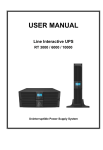
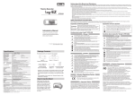
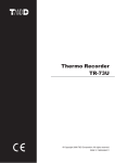
1
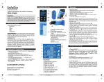
Cautions about using Input Modules
Exclusively for RTR-505 / TR-55i
The following items should be strictly obeyed for the safe usage of
these products, and for protecting yourself and other people from
bodily harm and/or damage to property. Before using any of these
products, please read the following carefully and fully understand the
contents.
Input Module User's Manual
- Do not connect any of the Input Modules in this manual to any Data Logger
other than RTR-505 / TR-55i.
- Do not take apart, repair or modify an Input Module.
- Use Input Modules only in an environment where the ambient temperature is
from -40 to 80°C and the humidity is 90%RH (no condensation) or less.
- For information about handling sensors and their necessary operating
environments, see the User's Manual included with the sensor.
- Do not use or store Input Modules in places such as listed below. It may result
in malfunction or unexpected accidents.
Carefully read this instruction manual before using any of these
products.
Thermocouple Module (TCM-3010)
PT Module (PTM-3010)
Voltage Module (VIM-3010)
Areas exposed to direct sunlight
In water or areas exposed to water
Areas exposed to organic solvents and corrosive gas
Areas exposed to strong magnetic fields
Areas exposed to static electricity
Areas near fire or exposed to excessive heat
Areas exposed to excessive dust or smoke
4-20mA Module (AIM-3010)
Pulse Input Cable (PIC-3150)
In this manual, the modules listed above are collectively referred to as (an / the)
"Input Module(s)" and RTR-505 / TR-55i as the "Data Logger".
- The sensor connection of Input Modules is not water resistant; make sure not
to get wet.
- Do not use alcohol to clean Input Modules. If an Input Module gets dirty, wipe
it with a soft cloth dipped in water and tightly wrung out.
- Do not drop or expose an Input Module to a strong impact.
- Do not use an Input Module on the human body.
- Store Input Modules out of the reach of children.
- If any smoke, strange smells or sounds are emitted from an Input Module,
immediately stop using.
- When making "Adjustment Settings" using the software, the adjustment values
will be saved to the Input Module. Therefore, when an Input Module is
replaced, it is necessary to re-make any desired adjustment settings to be written into the newly connected module.
Distributed by MicroDAQ.com, Ltd.
www.MicroDAQ.com
(603) 746-5524
T&D Corporation
http://www.tandd.com/
817-1 Shimadachi Matsumoto, Nagano 390-0852 JAPAN
Fax:+81-263-40-3152
© Copyright T&D Corporation. All rights reserved.
This is printed using recycled paper.
2012.03 16504750004 (1st Edition)
Thermocouple Module (TCM-3010)
78
54.5
14.5
47.8
78
27
27
14.5
PT Module (PTM-3010)
Unit: mm
Materials:
Polycarbonate
Measurement Item
Temperature
Compatible Sensors
Thermocouple: Type K, J, T, S
Measurement Range
-199 to 1700°C (only within the sensor heat-durability range)
Measurement Resolution
Type K, J, T : 0.1°C
Type S : about 0.2°C
Measurement
Accuracy*
Thermocouple
Measurement
±0.3 °C + 0.3 % of reading (Type K, J, T)
±1 °C + 0.3 % of reading (Type S)
Cold Junction
Compensation
±0.3°C (10 to 40°C), ±0.5°C (-40 to 10°C / 40 to 80°C)
The above mentioned temperature is the operating environment for Input
Module only.
Sensor Connection
Miniature Thermocouple Connector
Operating Environment
Temperature: -40 to 80°C, Humidity: 90%RH or less (no condensation)
* Sensor error is not included.
CAUTION
- When inserting a sensor into an Input Module, ensure that the polarity is correct by aligning the plus and minus signs
on the sensor connector and the module.
- The Data Logger detects the break of wire every 40 seconds or so, causing it to display an uncertain temperature
directly after a connector is removed.
- After connecting an Input Module to a Data Logger, check the thermocouple type (K, J, T, or S) of the sensor to be
used and the sensor type to be displayed on the LCD screen of the Data Logger; make sure they are the same. If
they are different, change the sensor type using the software.
- Measurement range is in no way a guarantee of the sensor heat-durability range. Check and confirm the heat durability of the sensor.
- When the sensor is broken or unconnected, the message "Err" will appear on the LCD screen of the Data Logger.
Connecting the Sensor
Check the
Sensor Type
Check the
Polarity
Back side
Vinyl Coated Electrical Wire
11 Check the sensor type and the polarity (plus and
minus signs).
21 Insert the sensor connector, aligning as shown
Unit: mm
Materials:
Polycarbonate
Vinyl Coated Electrical Wire
Measurement Item
Temperature
Compatible Sensors
Pt100 (3-wire), Pt1000 (3-wire)
Measurement Range
-199 to 600°C (only within the sensor heat-durability range)
Measurement Resolution 0.1°C
Measurement Accuracy*
±0.3°C+ 0.3% of reading (10 to 40°C), ±0.5°C + 0.3% of reading (-40 to 10°C / 40 to 80°C)
The above mentioned temperature is the operating environment for Input Module only.
Sensor Connection
Screw Clamp Terminal Block (3-Terminal)
Operating Environment
Temperature: -40 to 80°C, Humidity: 90%RH or less (no condensation)
Accessories
Protection Cover
* Sensor error is not included.
CAUTION
- After connecting an Input Module to a Data Logger, check the type (100Ω or 1000Ω) of the sensor to be used and
the sensor type to be displayed on the LCD screen of the Data Logger; make sure that they are the same. If they are
different, change the sensor type using the software.
- Make sure to correctly connect the lead wires according to the diagram shown on the terminal block, and securely
tighten the screws to the terminal block.
- The two "B" terminals have no polarity.
- Measurement range is in no way a guarantee of the sensor heat-durability range. Check and confirm the heat durability of the sensor.
- When the sensor is broken or unconnected, the message "Err" will appear on the LCD screen of the Data Logger.
Connecting the Sensor
Front Side
on the Input Module.
11 Loosen the screws of the terminal block.
21 Remove the protection cover from the Input Module,
and place it through the sensor cable.
31 Insert terminals A and B according to the diagram
shown on the terminal block.
Protection
Cover
Back side
41 Firmly tighten the screws to the terminal block.
51 Replace the protection cover over the terminal block.
Voltage Module (VIM-3010)
78
19.4
46
78
27
46
27
19.4
4-20mA Module (AIM-3010)
Unit: mm
Materials:
Polycarbonate
Measurement Item
Voltage
Input Voltage Range 0 to 999.9mV, 0 to 22V
Unit: mm
Materials:
Vinyl Coated Electrical Wire
Breakdown voltage: ±28V
Measurement
Resolution
up to 400mV: at 0.1mV, up to 800mV: at 0.2mV, up to 999mV: at 0.4mV, up to 3.2V: at 1mV, up
to 6.5V: at 2mV, up to 9.999V: at 4mV, up to 22V: at 10mV
Measurement
Accuracy
±0.5 mV + 0.3 % of reading (10 to 40 °C), ±1 mV + 0.5 % of reading (-40 to 10 °C / 40 to 80 °C)
The above mentioned temperature is the operating environment for Input Module only.
Input Impedance
mV Range: About 3MΩ, V Range: About 1MΩ
Preheat Function
Voltage Range (Preheating): 3V to 20V100mA, Time Range (Preheating): 1 to 999 seconds (in
units of one-second)
Diode for backflow prevention built in the "Preheat OUT" side
Sensor Connection
Cable Insertion Connection: 4-Terminal
Compatible Wires
Single wire: 0.32 to 0.65mm (AWG28 to AWG22), 0.65mm (AWG22) recommended
Twisted wire: 0.32mm2 (AWG22), 0.12mm or more in diameter
Strip length: 9 to 10mm
Operating
Environment
Temperature: -40 to 80°C / Humidity: 90%RH or less (no condensation)
Polycarbonate
Vinyl Coated Electrical Wire
Measurement Item
4-20mA
Input Current Range
0 to 20mA (Operational up to 40mA)
Measurement
Resolution
0.01mA
Measurement
Accuracy
±0.05 mA + 0.3 % of reading (10 to 40 °C),
±0.1mA + 0.3 % of reading (-40 to 10 °C / 40 to 80 °C)
The above mentioned temperature is the operating environment for Input Module only.
Input Resistance
100Ω ±0.3Ω
Sensor Connection
Cable Insertion Connection: Plus(+) 2 Parallel Terminals, Minus(-) 2 Parallel Terminals: Total 4
Terminals
Compatible Wires
Single wire: 0.32 to 0.65mm (AWG28 to AWG22), 0.65mm (AWG22) recommended
Twisted wire: 0.32mm2 (AWG22), 0.12mm or more in diameter
Strip length: 9 to 10mm
Operating
Environment
Temperature: -40 to 80°C / Humidity: 90%RH or less (no condensation)
CAUTION
CAUTION
- It is not possible to measure negative voltage with this module.
- When the signal source output impedance is high, a gain error will occur due to the change in input impedance.
- For details about the preheat function, see the User's Manual that comes with the software or the Help Menu in the
software you are using.
- Voltage to be input to "Preheat" should be 20V or lower. Inputting a higher voltage may cause damage to the Input
Module.
- When the preheat function is not being used, do not connect anything to the "Preheat IN" or "Preheat OUT".
- When using the preheat function, output signal GND(-) and power GND(-) need to be connected together.
- The LCD refresh interval for the Data Logger is basically from 1 to 10 seconds, but when using the preheat function
the LCD display will be refreshed based on the recording interval set in the Data Logger.
- When you remove the lead wires from the Input Module, core wires will be exposed; be careful of electric shock or
short circuits.
Connecting the Sensor
11 Using a screwdriver or tweezers, while
pressing down on the terminal button,
insert the wire into the hole.
Button
Hole
Example of Sensor Connection
VIM3010
Input
C
IN O
M
When using preheat
Preheat
O
U IN
T
+
out of the hole while pressing down on
the terminal button.
Signal
Output
-
11 Using a screwdriver or tweezers, while
pressing down on the terminal button,
insert the wire into the hole.
Example of Sensor Connection
It is possible to connect a sensor and a
voltage meter to the module at the same
time.
Voltage Meter
Button
Hole
21 Also when removing, gently pull the wire
out of the hole while pressing down on
the terminal button.
-
4-20mA
Sensor
+
-
+
OR +
OR +
BK BK -
-
Sensor
+
Connecting the Sensor
Battery
OR BK YL RD
21 Also when removing, gently pull the wire
- Do not apply electric current exceeding the input current range. Doing so may damage the Input Module, causing
heat or fire to occur.
(MAX: 100mA)
Power
+
Pulse Input Cable (PIC-3150)
100
1400
Distributed by MicroDAQ.com, Ltd.
www.MicroDAQ.com
(603) 746-5524
Unit: mm
Materials:
M3.5 Crimp Terminal
Vinyl Coated Electrical Wire
Measurement Item
Pulse Count
Input Signal
Non-voltage Contact Input / Voltage Input (0 to 27 V) Breakdown voltage: -5V, +27V
Detection Voltage
Lo: 0.5V or less, Hi: 2.5V or more
Chattering Filter
ON (15Hz or less) / OFF (3.5kHz or less) 0-3V Rectangular Wave Signal
High Level Pulse Width
Chattering Filter ON: 35ms or more, Chattering Filter OFF: 180μs or more
Low Level Pulse Width
Chattering Filter ON: 12ms or more, Chattering Filter OFF: 100μs or more
Response Polarity
Select either Lo->Hi or Hi->Lo
Maximum Count
61439 / Recording Interval
Input Impedance
Approx. 100kΩ pull up
Max Jitter
Normal: About 0.01 seconds, During Communication: About 0.1 seconds
CAUTION
- Note that the specifications listed above are for the RTR-505 / TR-55i being connected to this pulse input cable.
- When connecting the cable to the measurement object, make sure to check the terminal polarity (RD: +, BK: -) in
order to wire properly.
AIM-3010
100Ω