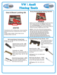
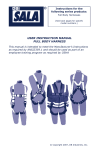
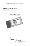
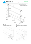
1
SERVICE BULLETIN:
Subject: Prevent Premature Water Pump Failure!
BLAUfergnugen! Inc. recommends that an Audi Vw Factory Trained ASE Certified Technician install your
parts to ensure your safety. Always read the factory service manual safety instructions and guidelines.
ALWAYS WEAR SAFETY GLASSES AND OTHER SAFETY ITEMS WHEN PERFORMING THE FOLLOWING WORK!
Installers Responsibility:
Blauparts recommends that installers take the necessary time to thoroughly follow the steps outlined in this bulletin to prevent future labor
costs, as well as any inconvenience after the installation of the water pump included in this timing belt kit. It has been noted that due to time
constraints, inconvenience, and profit, many individuals and mechanics alike, do not take the extra time needed to thoroughly flush the entire
vehicle cooling system prior to the installation of the new water pump. Just draining the cooling system and refilling the system is not enough!
Premature water pump failure (water pump seals and bearings) can occur because of failing to take the time to flush the entire cooling system
and its related components. Often when problems arise, such as a coolant leak, the new water pump is blamed as the cause when in fact the
opposite is true. It is usually because the installer has neglected to follow these steps listed below.
Flushing the Cooling System:
It is imperative that the cooling system be thoroughly flushed of all accumulated silt and sediment build up, including all aftermarket cooling
system additives, or stop leak products that may have been added to the cooling system, past or present. This would entail flushing the radiator,
engine block, heater core and hoses etc. Use Only Tap Water to flush the entire cooling system. DO NOT USE Cooling System Flush Products
since many contain muriatic and/or other acids. Remnants of such acids left in the cooling system can cause your new water pump to
prematurely fail.
Water Pump Installation:
Take extra time in cleaning the water pump gasket/o-ring mating surfaces. Make sure the surface is free of all old gasket material and corrosion
build up before installing your new water pump. It may be necessary to use a light abrasive scuff pad or razor blade. Gasket sealing agents
should NOT be used if your water pump includes a paper gasket. If the water pump mounting surface area on the engine block is throughly
cleaned, smooth and free from old gasket debris, gasket sealing agents (Form a Gasket products in gel or spray forms) are not needed. Sealing
agents vary in composition and intended usage, and when used in conjunction with paper gaskets may affect the paper gaskets’ long term
ability to compress and/or perform its sealing function. Appropriate gel like gasket sealing agents should only be used in the case of severe
pitting of the engine block surface whereby an even and smooth mounting surface for the water pump is not attainable. Double check all water
pump mounting bolts for tightness. A loose or missing water pump or thermostat housing bolt can result in a leak and falsely attributing the
water pump as defective.
Filling the Cooling System:
IMPORTANT: Read the Warnings on the antifreeze coolant bottle, improper use is HARMFUL or FATAL. Use only Audi, Vw G-12 antifreeze
coolant which was included in your timing belt kit . These bottles contain coolant that is concentrated. You must dilute the coolant. Mix 50%
coolant with 50% DEIONIZED WATER. DEIONIZED WATER IS PREFERRED. However, if it is not available use distilled water. DO NOT
MIX TAP WATER with new coolant if at all possible. Tap water varies in Ph and mineral content and depending on these factors, can adversely
effect your new water pump and other cooling system components.
Water Pump Break in Period:
All water pumps are inspected and air pressure tested at the factory for any leaks. However, new water pumps do have a break in period. It is
not uncommon for a new water pump to have some seepage of coolant from the discharge hole below the water pump pulley shortly after start
up. This is because the unique seal material in the new water pump is designed to ‘bed in’ as the impeller shaft spins. Slight weeping or
dampness from or around the discharge hole or cap is allowable for at least 100 miles after installation and should not be attributed as a
defective water pump.
Maintenance:
Mixing other brands of unauthorized antifreeze coolants with the approved G-12 antifreeze coolant included in your new timing belt kit can
also cause an adverse chemical reaction to G-12 coolant, causing the coolant to gel and clot. This can damage the new water pump, plug the
cooling system, and weaken other plastic cooling system components such as, the radiator and plastic coolant hose connections.
Environment:
Be environmentally responsible. Dispose of the old anti freeze coolant properly.
Page 1
Copyright© BLAUfergnügen ! Inc. 1997-2015
Revised 10-12
Form # Ins165/141
SERVICE BULLETIN:
Subject: Front Crankshaft Timing Belt Pulley Removal
Always read and follow Robert Bentley factory service manual safety instructions and guidelines.
Always wear safety glasses and other safety items when performing the following work.
Blaufergnugen! Inc. recommends that an Audi Vw Factory Trained ASE Certified Technician install your parts to ensure your safety.
PERTINENT TO: 1992-2005 Audi / Vw Models with V6 2.8L, 2.7L Engines
Please read the following information BEFORE removing the front crankshaft timing belt pulley on your engine!
Note the photos below for indication on the location of the small key located on the lower timing belt pulley.
Damaged Key
Original Key
BLAUfergnugen! Inc. has received reports of inadvertent damage occurring during the removal of the lower crankshaft
timing belt pulley. Reassembly using even a slightly damaged pulley can cause catastrophic engine failure. Thus, we've
decided to add the following information in regards to the lower timing belt pulley and front crankshaft seal.
Both Audi and Volkswagen engines have a lower timing belt pulley that utilizes a minimally sized ‘key’ (see illustration
below). This ‘key’ is devised to engage with the corresponding keyway in the crankshaft. It's been reported that while
loosening the main crankshaft bolt existing friction, corrosion rust, or stray thread locking compound between the bolt head
and pulley can inadvertently twist the small ‘key’ completely off the pulley or cause damage beyond safe reuse.
Additionally, because the ‘key’ engages just the tip of the crankshaft, the crankshaft keyway can also be damaged. Due to
the possibility of this damage, the installer may want to contemplate the immediate need for the removal of the lower
crankshaft timing belt pulley to access the front crank seal.
If there is no indication of oil leakage from the front crank seal, the installer may want to leave the lower crankshaft timing
belt pulley as is, not risking damage. However, if the front crank seal is leaking and needs to be replaced, you have little
option but to remove the pulley. Upon removal, it is crucial that you inspect the small ‘key’ protrusion found on the inside of
the pulley for damage. You must also inspect the very front edge of the crankshaft keyway for damage. If the crankshafts
keyway shows signs of damage and will no longer engage properly with the key on the pulley, short of complete
replacement, it may be possible to locate a qualified welder and have the end welded up and ground to shape.
BLAUfergnugen! Inc. has decided to stock the lower crankshaft timing belt pulley because of this problem for V6 30 Valve
engines (Item Number GG14000) and warns that by using a pulley that shows ANY signs of ‘key’ damage is unacceptable!
If reinstallation is attempted with a damaged pulley ‘key’ or crankshaft keyway, the lower crankshaft timing belt pulley can
easily fall out of time during main crankshaft bolt contraction, ultimately leading to catastrophic engine failure.
Page 2
Copyright © BLAUfergnügen! Inc. 2013
Revised 10-12 Form # Ins143/141
SERVICE BULLETIN:
Subject: Preventing Irreversible Damage to the Hydraulic Tensioner Damper
Application: 1998-2005 Audi / Vw Models with V6 2.8L 30V Engines
Please read the following information BEFORE proceeding with any timing belt service.
DISCLAIMER: Timing belt installation is a complex repair procedure and is to be performed by experienced automotive technicians, trained
in performing proper timing belt installation. Therefore, BLAUfergnugen! Inc. recommends that a Factory Audi / Vw ASE Certified
Technician, trained in timing belt installation for your exact vehicle model, install your parts. This is to ensure your safety and prevent improper
installation by untrained and unqualified installers, including technicians, which may lead to possible engine damage.
-Always read the factory service manual safety instructions and guidelines.
-Always wear safety glasses and other safety items/equipment when performing the following work.
IMPORTANT! General Hydraulic Tensioner Damper Guidelines (before installation):
If you have purchased our “Enhanced” version timing belt kit that includes a new hydraulic tensioner damper, You must position the Damper in an upright
position for (3) hours before installing to ensure proper hydraulic fluid distribution within the Hydraulic Damper Tensioner. The upright position is with
piston (C) at the top (see picture below). Do not remove the locking pin in the Damper without first reading all of the following steps. The lock pin tool T40011
should only be removed at the appropriate time described, as outlined in the accompanying instructions. If you accidently remove the pin before installation and
release (extend) the Damper piston, you must follow a specific procedure to compress the Damper piston properly or else you WILL CAUSE
IRREVERSIBLE DAMAGE to the Hydraulic Tensioner Damper.
CAUTION! Follow Instructions to Prevent Irreversible Hydraulic Tensioner Damper Damage!
It has been noted that some installers are NOT following the exact sequence of steps as outlined in the attached installation instructions (INS141). Even
automotive technicians appear to be skipping various steps outlined in the instructions in order to save time! Specifically, some installers have chosen to
not use the camshaft locking bar - special tool 3391 (Disassembly steps 14 -17)(Assembly steps 37-41) and crank locking pin - special tool 3242 (step 11). Also,
Installers in part or whole, have omitted or have incorrectly followed steps 11-18 or steps 31-41 on the accompanying instruction sheet (INS 141). Following the
correct sequence of steps are crucial to ensure Hydraulic Tensioner Dampers reliability. Additionally, upon re-assembly, during step 37-41, some
installers forgot to re-install the cam lock bar tool 3391. Caution: If you omit any of these crucial steps, your timing belt marks will likely not line up being a
tooth or several teeth off! You will then need to perform multiple attempts of re-trying to aline your timing belt marks in an effort to achieve correct
crankshaft/camshaft belt timing position. In these situations, you will need to compress the timing belt damper piston shaft in attempting to achieve correct engine
timing. CAUTION: In attempting to attain correct engine timing you need to compress the timing belt Hydraulic Damper tensioner Piston shaft. CAUTION: You
now run the risk of causing Irreversible damage to the Hydraulic Tensioner Damper during the operation of compressing the Damper’s pistion shaft
(C)!
CAUTION! Compressing the hydraulic tensioner damper Piston:
Compressing the timing belts Hydraulic Tensioner Damper is DANGEROUS and you can easily damage this part so that it cannot be used again!
CAUTION! If for some reason the piston shaft on your Hydraulic Tensioner Damper is in extended position (locking pin tool T40011 removed), or you need to
compress the timing belt damper piston in order to perform steps 37-41 again to reset timing belt tensionor timing, you must follow the procedures below very
carefully.
.
CAUTION! If the Hydraulic Tensioner Damper’s piston shaft (C) is in extended position (locking pin tool T40011 removed) and you compress the damper piston
shaft too rapidly, the hydraulic fluid within the hydraulic damper will be transferred out of one internal piston chamber and into another. This causes an incorrect
proportion of hydraulic fluid within the damper and weakens the hydraulic damper's force and its ability to apply correct timing belt tension. The Hydraulic
Tensioner Damper is now irreversibly compromised or damaged. Installing a compromised Hydraulic Tensioner Damper can lead to loose timing belt tension and
subsequent engine damage. Compromised dampers will be identifiable by having 5-10 mm of unrestricted piston shaft free play starting from the full extended
position. Do NOT use a compromised Hydraulic Tensioner Damper with piston shaft free play.
CAUTION! ONLY compress the Hydraulic Tensioner Damper mounted on the engine as shown in the images below. NEVER compress a Hydraulic
Tensioner Damper piston shaft in the horizontal (sideways) position such as a work shop bench vise. If the damper is compressed in the horizontal
position, this can cause an air pocket inside the tensioner damper, causing incorrect internal piston chamber fluid transfer and irreversible damage to the
Hydraulic Tensioner Damper.
How to Properly Compress the Hydraulic Tensioner Damper
Piston Shaft that is extended (locking pin tool T40011 removed):
ONLY compress the Hydraulic Tensioner Damper mounted on the engine.
Using a 8mm Allen socket and 3/8 drive rachet, as shown, slowly and gently
rotate tensioner pulley clockwise. This will allow tensioner pin (A) to push
upward on tensioner lever (B) and compress Hydraulic Tensioner Damper
shaft (C) until holes are aligned. Then install pin T40011 without scarring shaft
(C). An extremely slow and continuous even pressure should be applied
when compressing the Hydraulic Tensioner Damper shaft (C). You should
take, at minimum, 5 minutes to compress the damper piston shaft!
Failure to follow this proceedure (at minimum, 5 minutes to compress),
and compressing the Damper too quickly will cause Irreversible damage!
How to Properly Set Timing Belt Tension with the Hydraulic
Tensioner Damper: (Steps 37,38 INS 141)
Once pin T40011 has been removed, slowly rotate tensioner pulley counter
clockwise to around 7 ft lbs. This will allow Hydraulic Tensioner Damper shaft (C)
to extend pushing upward onto tensioner lever (B) and then pushing onto
tensioner pulley pin (A), thus applying proper tension to the timing belt. Then,
torque tapered camshaft pulleys to 41 ft. lb. There is no need to compress
the hydraulic tensioner damper to personal tension. Next, use a 1/2 inch
24mm 12-point socket and rachet to rotate the engine by the crankshaft.
Rotate the engine in the clockwise direction two full engine revolutions. This will
allow the damper to compress automatically and give the timing belt its proper
Page 3
A
B
C
All rights reserved - Copyright© BLAUfergnügen ! Inc. 2013
T40011
Revised 10-12
Form # Ins157/141
Guidelines For Installation Of Your 2.8L 30 Valve V6 Timing Belt Kit
!CAUTION PLEASE READ!
Performing work on your automobile without having proper knowledge, mechanical ability or the proper tools and safety
equipment, CAN CAUSE SEVER DAMAGE TO YOUR AUTOMOBILE AS WELL AS HUMAN INJURY OR DEATH!
BLAUfergnugen! Inc. Recommends you have a A.S.E Certified Technician install your parts to ensure your safety.
The following information contains guidelines and are not intended to replace the official factory manual. Always refer to the
factory manual for proper installation and safety guidelines.
>Before proceeding with the following guidelines locate and follow the bumper cover removal section for your specific vehicle as
found starting on page 12 of this document.
1) With bumper cover removed, proceed to remove all decorative engine covers.
2) IMPORTANT, PLEASE READ ATTACHED BULLETIN REGARDING THIS NEXT STEP. Drain the remaining coolant from the
engine block by removing the drain plug located in the bottom of the block, just behind the drivers side of the sub-frame. The 6mm allen
fastener will be in a machined recessed area on the engine side of the bell housing. Reinstall this fastener when system has been drained.
(Image 1)
3) Compress the two pressure clips on the secondary air pump pipe, pull outward and place off to the side. (Image 2)
4) Use a 17mm socket wrench to remove the accessory belt by rotating the belt tensioner clockwise. (Image 3)
5) Use a 10mm allen wrench to remove the spring loaded accessory belt tensioning device. (Image 4)
IMAGE 1
IMAGE 2
IMAGE 3
IMAGE 4
IMAGE 2
Page 4
Copyright© BLAUfergnügen ! Inc. 2013
Revised 10-20
Form # Ins 141
6) Using a 6mm allen wrench and tool 3212 remove the power steering pump pulley. (Image 5) (When using tool 3212 have arms of tool
spread as far apart as possible to not bend or brake tool.)
7) Remove the viscous fan assembly by using special tools 3312 and 3212. The unit has a left hand thread, so you must remove it by turning
the fastener in a clockwise direction. These, at times may be very tight and will need some patience. (Image 6) (When using tool 3212 have
arms of tool spread as far apart as possible so to not bend or brake tool.)
8) Remove all 3 timing belt covers. These are held in place by several clips on the top and bottom of each cover. (Image 7)
9) Remove the viscous fan pulley bracket. To remove the fan pulley bracket, locate two 6mm allen fasteners hidden on the lowest portion of
the fan pulley bracket. There will be two additional fasteners that are located and accessed through the pulley. One is a 5mm allen fastener
located at about 11 o’clock through one of the small holes and the other is a 6mm allen fastener located at about 6 o’clock through one of the
oval shaped holes. (Image 8)
IMAGE 5
IMAGE 6
IMAGE 7
IMAGE 8
10) Rotate the engine by the crankshaft with a 12 point 24mm socket wrench in a clockwise direction to align all timing marks. To accomplish
this you will be lining up two engine timing marks. One will be your crankshaft timing mark and the other will be the camshaft timing marks.
To align the crankshaft timing mark there will be a machined line in the crankshaft vibration damper that will coinside with an arrow mark on
the lower most timing belt cover. (Image 9) Simultaneously the two largest holes on each diamond shaped camshaft washer should be pointed
directly inward. (Image 10)
Images 9 and 10 on next page
Page 5
Copyright© BLAUfergnügen ! Inc. 2013
Form # Ins 141
IMAGE 9
IMAGE 10
11) Crankshaft locking plugs can be a plastic cap or a metal threaded allen plug. Using a 10mm wrench (plastic cap) or 6mm allen (threaded plug) , remove the
crankshaft locking plug cap. This plug is located under the driver’s side engine motor mount bracket. To access this you will need to bend the motor mount
harness bracket off to the side. (Image 11) When you remove the plug, be careful to not lose its companion O-Ring seal. (Image 12) When you are assured
that the engine timing marks are aligned, thread crankshaft locking pin tool 3242 in place and lightly tighten with a 10mm wrench. With 12 point 24mm
socket wrench, double check that the crankshaft will not move by lightly trying to turning the crankshaft.
IMAGE 11
IMAGE 12
12) Use a 6mm allen wrench to remove the vibration dampener/serpentine belt pulley from end of crankshaft. (Image 13)
13) Use a 10mm socket wrench to remove bolts holding the lower most timing belt pulley cover in place. (Image 14)
14) Use cam lock bar tool 3391 (Tool 3391 can be a single or three piece tool.) to loosen the tapered camshaft pulleys from each camshaft.
Loosen camshaft fasteners until they can be hand loosened. The tapered camshaft pulleys must be loosened to properly set the engine timing
during reassembly. (Image 15)
15) By hand loosen the cam pulley bolts about 3-4 full turns. This will allow an air gap between the fastener washer and the diamond shaped
washer. (Image 16)
16) Remove cam lock bar tool 3391.
IMPORTANT, PLEASE READ: The camshafts do not have key ways in them. They are tapered camshafts and are held in place by the
conical shape of the camshaft and pulley being tightly pressed together when tightened. For camshaft timing reference, the two largest holes
on each diamond shaped camshaft washer should be pointed directly inward. When the diamond shaped washers are removed there will be a
large flat spot on the cone of the camshafts, this is also a timing reference. These flat spots also always point inward. Always make sure the
diamond shaped washers mate properly to the camshafts when being installed. If the camshafts by chance move manually turn them back into
place. During reassembly the tapered camshaft pulleys must be loosened to properly set engine timing and timing belt tension. If the timing
belt tension is set without the tapered camshaft pulleys being loosened and reset proper engine timing and timing belt tension will not be
attained. If the camshaft sprockets are not loosened and reset this can cause misalignment of the timing belt as well as binding of the timing
belt causing premature timing belt and timing belt component wear. (Image 17 and 18)
Images 13,14,15,16,17, and 18 on next page
Page 6
Copyright© BLAUfergnügen ! Inc. 2013
Form # Ins 141
IMAGE 13
IMAGE 14
IMAGE 15
IMAGE 16
IMAGE 17
IMAGE 18
17) Use puller T4001 to slowly and evenly apply tension to the tapered camshaft pulleys until they pop loose. By doing this in a slow and even
manner you will avoid warping your cam pulley and damaging the tool. (Image 18)
Page 7
Copyright© BLAUfergnügen ! Inc. 2013
Form # Ins 141
18) IMPORTANT, PLEASE READ ATTACHED SERVICE BULLETIN INS 157/141 REGARDING THIS NEXT STEP. Using a 8 mm
Allen wrench, VERY SLOWLY AND EVENLY turn the hydraulic damper/idler pulley CLOCKWISE to compress the hydraulic damper.
This will loosen tension on the old timing belt. Align and insert pin tool T40011 into the hole near the top of the hydraulic damper to keep the
damper retracted and the belt loose. Failure to compress the hydraulic tensioner damper in a very slow manner can result in the incorrect
transfer of fluid within the hydraulic tensioner damper and loose its ability to tension the timing belt. (Image 19)
19) Remove the old timing belt and components.
20) IMPORTANT, PLEASE READ ATTACHED SERVICE BULLETIN INS 165/141 REGARDING THIS NEXT STEP. Remove old
water pump. Thoroughly clean the gasket mating surfaces of all old material so it is squeaky clean!!
21) If new thermostat is supplied, remove thermostat housing and old thermostat along with o-ring located just below the passenger side
cylinder head. Be prepared to use a catch pan for a small amount of fluid left within this manifold even after draining the coolant system. Some
thermostats may be difficult to remove because of the bond that can establish between dissimilar materials over time. A tap with the
handle end of a small hammer may be in order. Thoroughly clean out the recessed area where the new thermostat mates to the
block. On your model vehicle there are two types of thermostat housings. One is an aluminum housing which is held in place with two 10mm
fasteners and the second is plastic which has a hidden fastener on the bottom side of the housing. (Image 21) In some cases both 5mm allen
type fasteners and 10mm bolts could have been used. (If needed remove two coolant hoses)
22) Install your new water pump and gasket. Make sure the gasket does not fold over causing improper sealing. Evenly tighten fasteners by
working your way around the water pump, and lastly torque 10mm bolts to 7ft lbs. (Image 20)
23) Install the new updated thermostat, then o-ring so the spring support bar is in a level and or horizontal position as pictured.
(Image 22)
IMAGE 19
IMAGE 20
IMAGE 22
IMAGE 21
24) IMPORTANT, PLEASE READ ATTACHED SERVICE BULLETIN INS 143/141 REGARDING THIS NEXT STEP. It is
recommended to purchase a new Crankshaft Timing Pulley Kit part number GG1400 when performing steps 24-27. If your crank seal
is not leaking you can choose to not perform steps 24-27 for the replacement of the crank seal. With crankshaft locking pin tool 3242
still in place, Use a 3/4“ breaker bar with 12 point 24mm socket to remove the main crankshaft bolt, then remove the toothed pulley.(Image 23)
Page 8
Copyright© BLAUfergnügen ! Inc. 2013
Images 23 on next page
Form # Ins 141
25) Use tool 3203 to remove the lower crank seal. Inspect Crankshaft for a possible groove where the old seal engaged the crankshaft.
Lubricate lip of new seal with clean motor oil, then with tool 3203, gently tap new seal into place. If the crankshaft is grooved, recess the seal
a few millimeters deeper so that it rides on a new mating surface.
26) Reinstall crankshaft toothed belt pulley and tighten to torque spec. - Torque spec for this fastener is 148ft lb + ½ turn.
27) Remove the camshaft bolts and pulleys, keeping track of which pulleys belongs with which side. Using a 10mm socket wrench remove
both rear timing belt backing covers. (Image 24)
IMPORTANT, PLEASE READ: The camshafts do not have key ways in them. They are tapered camshafts and are held in place by the conical shape of the
camshaft and pulley being tightly pressed together when tightened. For camshaft timing reference, the two largest holes on each diamond shaped camshaft
washer should be pointed directly inward. When the diamond shaped washers are removed there will be a large flat spot on the cone of the camshafts, this is
also a timing reference. These flat spots also always point inward. Always make sure the diamond shaped washers mate properly to the camshafts when being
installed. If the camshafts by chance move manually turn them back into place. (Image 17)
IMAGE 23
IMAGE 24
28) Remove old camshaft seals one at a time using tool 3240BL. (For proper use of tool please refer to the instruction sheet supplied with tool
kit.) Thoroughly clean cam seal contact area and inspect for any grooves created by old seals. Apply a thin coat of clean motor oil to the new
seals lip, then use tool 3241/1 to press in the new seals for each camshaft. If any grooves are present from the inspection above, attempt to
locate the new seals slightly deeper in order to contact a fresh new area of the camshaft.
29) Reinstall timing belt backing covers with blue thread locker and torque 10mm bolts to 7ft lbs.
30) Reinstall the camshaft toothed pulleys back onto each appropriate camshaft. Install the bolts to retain the pulleys, but leave them finger
tight for now. Always make sure the diamond shaped washer are inserted properly onto each end of the camshafts with the largest holes
pointing inward.
31) If hydraulic damper is supplied in your kit install and torque 10mm bolts to 7ft lbs. (Image 25) WARNING! Do not remove hydraulic
tensioner damper pin tool T40011.
32) If tensioner lever is supplied in your kit install and torque 12mm bolt to 18ft lbs. (Image 26) Note the stacking of washers and the liner when
installing. You may also lightly coat the liner with grease. Warning! Failure to install compentents in the proper order will cause binding and timing
belt failure.
IMAGE 25
Page 9
Copyright© BLAUfergnügen ! Inc. 2013
IMAGE 26
Form # Ins 141
33) Install timing belt tensioner and torque 6mm allen to 18ft lbs. Note the stacking of washers and the liner when installing. You may also
lightly coat the liner with grease. (Image 27) Check to make sure tensioner pin (A) makes proper contact with tensioner lever (B). (Image 28)
34) By hand rotate and test that the tensioner lever and tensioner move freely. If there is binding, this could be due to the tensioner liner or
lever being installed incorrectly. If needed proceed to step 31 and double check your work. (Image 29)
35) Install timing belt idler and torque 17 mm bolt to 33ft lbs. (Image 30)
36) Install the new timing belt by positioning it over the lower crank pulley and begin to work upwards, placing it around the tensioners and
lastly to the passenger side cam pulley. Make sure timing belt is routed evenly around all pulleys and tensioners.
IMPORTANT, PLEASE READ: It is very important to always note the stack of washers as well as liners supplied with tensioner components. If the washers
and or liners are not used correctly this can cause miss alignments to the timing belt and thus risk damage to the tensioners, timing belt or engine. After the
tensioner components have been installed always double check for ease of movement, making sure they all rotate properly with no binding.
37) Install cam lock bar tool 3391 to hold both camshafts in place. (Tool 3391 can be a single or three piece tool.)
IMPORTANT, PLEASE READ: The camshafts do not have key ways in them. They are tapered camshafts and are held in place by the conical shape of the
camshaft and pulley being tightly pressed together when tightened. For camshaft timing reference, the two largest holes on each diamond shaped camshaft
washer should be pointed directly inward. When the diamond shaped washers are removed there will be a large flat spot on the cone of the camshafts, this is
also a timing reference. These flat spots also always point inward. Always make sure the diamond shaped washers mate properly to the camshafts when being
installed. If the camshafts by chance move manually turn them back into place. (Image 17)
Page 10
IMAGE 27
IMAGE 28
IMAGE 29
IMAGE 30
Copyright© BLAUfergnügen ! Inc. 2013
Form # Ins 141
38)With a 8mm allen wrench, apply just enough clockwise tension to the belt tensioner to allow the lock pin T40011 to be removed from
the hydraulic damper. (Image 31)
Caution: The Hydraulic Damper is under pressure and must be compressed slowly. Failure to compress the Hydraulic Damper Slowly can cause irreversible
damage to the Hydraulic Damper. SEE ATTACHED SERVICE BULLETIN INS 157/141. Do not scratch or scar the shaft of the Hydraulic Damper as this
can damage the Hydraulic Damper.
39) With a 8mm allen wrench pre-load the tensioner in a counterclockwise direction to around 7ft lbs. This will allow the hydraulic damper to
extend out and subsequently apply the correct tension to the new belt. (Image 32)
40) With cam lock bar tool 3391 still in place, torque 16mm bolts retaining the cam pulleys to 41ft lb. (Image 33)
41) Remove both the crankshaft and the camshaft locking tools 3391 and 3242. Then rotate the engine a full two revolutions by hand to assure
that there is no interference. Double check that the appropriate crankshaft and camshaft timing marks line up perfectly.
42) Reinstall the crank lock plug with o-ring and torque 10mm bolt to 7ft lb. (Image 12)
43) Reinstall lower most timing belt pulley cover and torque 10mm bolts to 7ft lbs with blue thread locker. (Image 14)
44) Reinstall crankshaft vibration dampener/serpentine pulley and torque 6mm allens to 18ft lb. (Image 13)
45) Reinstall viscous fan bracket and fan. Remember the left hand thread involved with the fan. (Image 6 and 8) (Note: the fan bracket
instals over the top of the lower most timing belt cover tab area. If the fan bracket is installed with the lower most timing belt cover in front of the fan bracket it will rub the
crankshaft vibration damper.) Torque specs are as follows: (3) 6mm allen fasteners - 17 ft lb. (1) 5mm allen fasteners - 7 ft lb. Fan clutch unit - 27 ft lbs.
46) Reinstall both the upper and lower radiator hoses.
47) Reinstall all timing belt covers, being assured there is no rubbing on any of the timing belt components. (Image 7)
48) Using a 6mm allen wrench and tool 3212, reinstall the power steering pump pulley and torque 6mm allens to 18ft lbs. (Image 5)
59) Reinstall serpentine tensioner and torque 10mm allen to 41ft lbs. Make sure pin on the tensioner lines up properly with engine block.
(Image 4)
50) Install serpentine belt. Make sure the belt is set properly in all ribs on pulleys. Use image 3 to help with belt direction.
51) Install plastic breather hose pipe on front side of engine. (Image 2)
52) Locate any components removed not specifically addressed in this guideline and re-install. Review each step found in this set of guidelines
to ensure each component has been addressed properly and has been re-fastened to specification.
IMAGE 32
IMAGE 31
IMAGE 33
Page 11
Coolant system filling next page
Copyright© BLAUfergnügen ! Inc. 2013
Form # Ins 141
IMPORTANT, PLEASE READ ATTACHED BULLETIN REGARDING THESE NEXT STEPS.
COOLANT SYSTEM FILLING:
53) Loosen the clamp on the coolant hose that runs up to the heater core. Pull the hose back until the small bleeder hole located near the end of
the hose is no longer sealed. (Image 34)
54) Slowly fill the coolant expansion tank with a 50/50 mixture of coolant/antifreeze and distilled water until it flows from the bleeder hole in
the above heater core hose. In some cases it is best to unscrew the expansion tank mounting fasteners and lift upward to allow gravity to better
help the coolant/antifreeze system to be burped. When this is completed you can re-fasten the expansion tank.
55) Push heater hose back into place and re-affix clamp.
56) Locate coolant bleeder screw on crossover pipe just under coolant expansion tank. Loosen screw. (Image 35)(You may have to move
coolant expansion tank off to the side. On some models you will not have to locate this bleeder screw as there is a coolant hose that will allow
the system to be burped directly into the coolant/antifreeze expansion tank.)
57) Continue to add coolant until it flows from the above bleeder, then tighten bleeder screw.
58) Locate and loosen an additional bleeder screw on the front coolant pipe, next to the drivers side head. (Image 36)
59) Once again, add coolant until it flows from the above bleeder and then tighten bleeder screw.
60) Top off coolant level to the max mark of the expansion tank and install the expansion tank cap.
61) Set heater controls to the maximum heat position.
62) Start engine and let run at idle for 10 to 15 minutes.
63) Elevate engine RPM between 2000-4000 RPM at a gradual rate for approximately 10-15 minutes. (You might have to turn off the engine
and allow the engine to cool for 20-30 minutes and then repeat step 51 to allow proper burping/removal of air in cooling system.)
64) Allow engine to idle until the lower coolant hose on the radiator is hot.
65) Turn off engine.
66) When engine has cooled re-check coolant and add as needed.
IMAGE 34
Page 12
IMAGE 35
IMAGE 36
Copyright© BLAUfergnügen ! Inc. 2013
Form # Ins 141
Guidelines For Audi A4 1996-01 Front Bumper Removal
! CAUTION !
Performing Work on Your Automobile Without Having Proper Knowledge, Mechanical Ability
or the Proper Tools and Safety Equipment, CAN CAUSE SEVERE INJURY OR DEATH !
BLAUfergnugen! Inc. recommends you have an A.S.E. Certified Technician install your parts to ensure your safety.
ALWAYS WEAR SAFETY GLASSES AND OTHER SAFETY ITEMS WHEN PERFORMING THE FOLLOWING WORK
The following information is simply a guideline and is not intended to replace the official Bentley Factory Manual.
Always refer to the factory manual for proper installation and safety guidelines.
1) Elevate vehicle on an automotive lift or proper jack stands and remove the lower splash pan.
2) If your car is equipped with fog lights, you must unplug the lower fog lights. Remove the lower bumper grilles to access the
the electrical plugs through the openings. If your vehicle does not have fog lights, just remove the lower bumper grilles.
3) Pinch off the vehicle side of the headlamp washer hose and push down on the plastic latch clip to separate the connector.
This hose is located on the drivers side of the vehicle just behind the bumper cover.
(Be careful not to break or destroy the clip as it will need to be reused) (Image 1)
4) Locate and remove the (2) fasteners from inner fender liner in front of each tire (one fastener on each side of vehicle). (Image 2)
5) Locate and remove (2) fasteners located in the top of each bumper grille opening (one fastener on each side of vehicle). (Image 3)
Image 1
Image 2
Image 3
6)To slide the bumper cover out and off push strait down on the bumper cover between the fender and bumper cover seam just
behind the headlight. At the same time well pushing down place your second hand near the wheel well area and pull out. The top of
the bumper cover should pop out of the bracket. Then grab the lower side of the bumper and pull upward and out to pop the bumper
cover out of the lower side of the bracket. Apply this step on both sides of the bumper cover. (Image 4)
7) Locate and remove the (2) fasteners that hold the air box intake to the radiator valance. Pull upward on the duct closest to the air
box and then remove the duct. (Image 5)
Image 4
Page 13
Image 5
Copyright© BLAUfergnügen ! Inc. 2013
Form # Ins141
Guidelines For Audi A4 1996-01 Front Bumper Removal continued..........
8) Remove the engine bay seal that runs across vehicle from fender to fender along the front side of the engine bay.
9) Remove the upper and outermost fasteners located near the bumper shock brackets and then thread tool 3369 into those same threaded
holes. When tool 3369 is in place on each side of the vehicle, remove the remaining fasteners from brackets. (Image 6)
10) Locate and remove the (4) upper radiator valance fasteners located at the forward fender edge on each side of vehicle. (Image 7)
11) Locate and remove the (2) fasteners holding the lower front edge of fender to the radiator valance. These fasteners are located just under
headlamp on each side of the vehicle. (Image 8)
Image 6
Image 7
Image 8
12) Locate and remove the (2) fasteners that hold the power steering cooler tube in place. This cooler is located directly in front of the
radiator, A/C condensor. Let cooler tube hang free, ensuring it does not get damaged. (Image 9)
13) Locate the radiator drain screw at the lower front drivers side of the radiator. Drain the coolant from the system into a suitable drain pan.
(Image 10)
14) Remove both the upper and lower radiator hoses by gently prying with a screwdriver on the removal clip found integrated into the hose
clamp. (Image 11)
15) If the vehicle has a 1.8L turbocharged 4 cylinder engine, you will need to remove the lower intercooler hoses that connect to the crossover
pipe. If the vehicle has the 2.8L 6 cylinder engine skip this step.
16) Slide the entire front radiator and support assembly forward along the previously installed special tool 3369.
.
Image 9
Page 14
Image 10
Copyright© BLAUfergnügen ! Inc. 2013
Image 11
Form # Ins 141
Guidelines For Audi A6 1998-04 Front Bumper Removal
!CAUTION PLEASE READ!
Performing work on your automobile without having proper knowledge, mechanical ability or the proper tools and safety
equipment, CAN CAUSE SEVER DAMAGE TO YOUR AUTOMOBILE AS WELL AS HUMAN INJURY OR DEATH!
BLAUfergnugen! Inc. Recommends you have a A.S.E Certified Technician install your parts to ensure your safety.
The following information contains guidelines and are not intended to replace the official factory manual. Always refer to the
factory manual for proper installation and safety guidelines.
1) Elevate vehicle on an automotive lift or proper jack stands and remove the lower splash pan.
2) Unplug the lower fog lights and horns. You will be able to access the electrical plugs from behind the bumper cover. There are a total of two
horns, one on each side, located just above the fog lights. (Image 1)
3) Pinch off the vehicle end of the headlamp washer hose and remove the plastic clip. This hose is located on the driver side of the vehicle
just in front of the windshield washer tank. (Be careful not to break or destroy the clip as it will need to be reused.) (Image 2)
4) Locate and remove the (2) 10mm fasteners from each inner fender liner, just in front of each tire. (Image 3)
Image 1
Image 2
Image 3
5) Locate and remove the (6) 10mm nuts that hold the bumper cover ends to the inner fenders. These fasteners are located behind the bumper
cover, inside the forward edges of the inner fenders. (Image 4)
6) Remove the lower passenger and driver side bumper grilles, locate and remove the fasteners located in the top of each grille opening
(one fastener per side). (Image 5)
7) With a firm grip, pull forward and outward on the bumper cover on each side of the vehicle. Use caution while slowly working your way to
the middle of the bumper cover, then fully remove the bumper cover. (Image 6)
Image 4
Page 15
Image 5
Copyright© BLAUfergnügen ! Inc. 2013
Image 6
Form # Ins 141
Guidelines For Audi A6 1998-04 Front Bumper Removal continued ........
8) Remove the upper and outermost fasteners located near the bumper shock brackets on each side of the vehicle. Then, thread tool 3369 into
those same threaded holes. When tool 3369 is in place on each side of the vehicle, remove the fasteners from bumper shock brackets.
(Image 7)
9) Locate and remove the (2) fasteners that hold the air box intake to the radiator valance. Pull upward on the duct closest to the air box and
remove the duct.
10) Locate and remove the (4) upper radiator valance fasteners located at the forward fender edge on each side of vehicle. (Image 8)
11) Locate and remove the (2) fasteners holding the lower front edge of fender to the radiator valance. These fasteners are located just under
the headlamp on each side of the vehicle. (Image 9)
(Images below are from a different model but similar)
Image 7
Image 8
Image 9
12) Remove the engine bay seal that runs across vehicle from fender to fender along the front side of the engine bay.
13) Locate and remove the (2) fasteners that hold the power steering cooler tube in place. This cooler is located directly in front of the
radiator, A/C condensor. Let cooler tube hang free, ensureing that it does not get damaged.
14) Drain the coolant from the coolant system into a suitable drain pan. Note the following drain methods or locations by engine:
2.8L Engines - You must remove the lower radiator hose located on the lower passenger side rear of the radiator by pulling up
on the radiator hose clip, then pull straight back on the hose being very careful not to crack the radiator.
2.7T Engines - Unscrew the radiator drain screw located on the lower driver side front of the radiator.
3.0L Engines - Unscrew the lower radiator hose drain plug located at the lower passenger side rear of the radiator on the hose.
4.2L Engines - Unscrew the radiator drain screw located on the lower driver side front of the radiator.
15) Remove the upper and lower radiator hoses by gently prying on the removal clip integrated into the hose clamp with a screw driver blade.
16) Slide the entire front radiator and support assembly forward along the previously installed special tools 3366.
Page 16
Copyright© BLAUfergnügen ! Inc. 2013
Form # Ins 141
Guidelines For Bumper Cover Removal - Passat 2001-2005
!CAUTION PLEASE READ!
Performing work on your automobile without having proper knowledge, mechanical ability or the proper tools and safety
equipment, CAN CAUSE SEVER DAMAGE TO YOUR AUTOMOBILE AS WELL AS HUMAN INJURY OR DEATH!
BLAUfergnugen! Inc. Recommends you have a A.S.E Certified Technician install your parts to ensure your safety.
The following information contains guidelines and are not intended to replace the official factory manual. Always refer to the
factory manual for proper installation and safety guidelines.
1) Elevate vehicle on an automotive lift or proper jack stands and remove the lower splash pan.
2) Remove the lower drivers and passengers side bumper grilles. Reach in behind the fog light and unplug the electrical connectors.
3) Remove the main hood latch mechanism by removing the (3) 10 mm fasteners and the electrical plug. Additionally, remove the secondary
hood release lever. Pry up and remove the spring clip from the hood latch lever, then use a flat blade screwdriver to spread the latch apart so
that the rod clears the latch pins. Next, remove the latch and place it off to the side. (Images 1 and 2)
4) Remove the main grille by removing (2) Torx head fasteners, one located at each side of the grille. Firmly pull up on the grille until the
grilles lower mounting tabs pop out. (Images 3 and 4)
Image 1
Image 2
Image 3
5) With the main grille removed, locate and remove the (4) Torx screws found in lower grille cavity. (Image 5)
6) Locate and remove the fasteners located on the forward side of each wheel well. You will find a total of (4) fasteners in each wheel well,
with one being rather hidden toward the very top of each wheel well as pictured. (Image 6)
Image 4
Page 17
Image 5
Copyright© BLAUfergnügen ! Inc. 2013
Image 6
Form # Ins 141
Guidelines For Bumper Cover Removal - Passat 2001-2005 Continued.................
7) Remove the bumper cover by firmly pulling the cover forward, one side at a time. While pulling the bumper cover forward, you will need to
unplug the electrical connectors for the amber side indicator lamps, found on each side of the bumper. (Image 7)
8) Locate and remove the (5) fasteners that hold the upper plastic bumper cover reinforcement, also the (2) fasteners holding the lower
steel bumper cover reinforcement. (Image 8)
9) Remove the upper outer fasteners from the bumper shock brackets on each side of vehicle, replace fasteners with special tool 3411. Once
installed, remove all remaining fasteners from bumper shock brackets. (Image 9)
Image 7
Image 8
Image 9
10) Remove the (2) fasteners that hold the air box intake tube in place, then pull upward on intake tube to completely remove it.
11) Remove the upper radiator valance fastener located at the forward fender edge on each side of vehicle. (Image 10)
12) Locate and remove (2) fasteners holding the fender to the radiator valance, one fastener found under each headlamp. (Image 11)
Image 10
Image 12
Image 11
13) Remove the fasteners that hold the power steering cooler in front of the radiator. Let
cooler tube hang free, ensuring it does not get damaged. (Image 12)
14) Drain the coolant out of the radiator by opening the drain screw found on the lower
drivers side of the radiator. (Image 13)
15) Remove the lower intercooler hoses from the intercooler crossover pipe.
.
16) Remove the upper and lower radiator hoses by gently prying on the removal clip
integrated into the hose clamp with a screwdriver blade.
17) Slide entire radiator and front support assembly forward on the pair of previously
installed special tool 3411.
Image 13
Page 18
Copyright© BLAUfergnügen ! Inc. 2013
Form # Ins 141
Guidelines For Bumper Cover Removal - Passat 1998-2000
!CAUTION PLEASE READ!
Performing work on your automobile without having proper knowledge, mechanical ability or the proper tools and safety
equipment, CAN CAUSE SEVER DAMAGE TO YOUR AUTOMOBILE AS WELL AS HUMAN INJURY OR DEATH!
BLAUfergnugen! Inc. Recommends you have a A.S.E Certified Technician install your parts to ensure your safety.
The following information contains guidelines and are not intended to replace the official factory manual. Always refer to the
factory manual for proper installation and safety guidelines.
1) Remove (2) phillips screws on radiator support to remove air box intake tube. (Image 1)
2) Remove hood seal gasket that runs across front radiator support from fender to fender.
3) Use a 10 mm socket to remove (3) 8 mm bolts that secure hood latch to radiator support. (Image 2)
4) Remove hood latch grommet. (Image 3)
Image 1
Image 2
Image 3
5) Use a T-25 torx driver to remove the (3) screws on top of radiator support surrounding the hood latch. (Image 4)
6) Remove the driver and passenger side turn signal lamps by removing spring clips. (Image 5)
7) Use a 10 mm socket to remove (1) front bumper cover bolt found in bottom edge of turn signal cavities on both driver and passenger side of
vehicle. (Image 6)
Image 4
Page 19
Image 5
Copyright© BLAUfergnügen ! Inc. 2013
Image 6
Form # Ins 141
Guidelines For Bumper Cover Removal - Passat 1998-2000 continued.............
8) Use a T-25 torx driver to remove (3) screws from each of both driver and passenger side wheel wells in front of tires. (Image 7)
9) Use a T-25 torx driver to remove (1) 10 mm screw located behind inner fender skirt on both driver and passenger side of vehicle. You must
pry away the skirt material in order to obtain access to these screws. (Image 8)
10) Remove (2) Philips screws securing hood bump stops just to the inside of each headlamp. (Image 9)
Image 7
Image 8
Image 9
11) Firmly grab passenger side corner of bumper cover, gently pull forward until corner of
cover comes loose. Gently manipulate the top center of the bumper cover over, clearing
the hood latch release knob. If the hood latch release knob will not allow the hole in
the bumper cover to clear, you may need to carefully trim or enlarge the hole around the latch.
When bumper cover has cleared the latch knob, grab the bumper cover and remove. Store
bumper cover in a safe place until it can be reinstalled. (Images 10, 11 and 12)
12) Use a 13 mm socket to remove (2) front bumper reinforcement bolts and remove front
bumper reinforcement (Image 13)
Image 10
Image 11
Image 12
Image 13
13) With bumper cover removed, you may now continue with related service. For reinstallation, follow these guidelines in reverse order.
When done, recheck all listed steps to ensure the work was done properly.
Page 20
Copyright© BLAUfergnügen ! Inc. 2013
Form # Ins 141