1
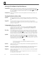
ÎÎ GE Fanuc Automation Programmable Control Products Series 90 -30 I/O Link Master Module User’s Manual GFK-0823A July 1994 GFL-002 Warnings, Cautions, and Notes as Used in this Publication Warning Warning notices are used in this publication to emphasize that hazardous voltages, currents, temperatures, or other conditions that could cause personal injury exist in this equipment or may be associated with its use. In situations where inattention could cause either personal injury or damage to equipment, a Warning notice is used. Caution Caution notices are used where equipment might be damaged if care is not taken. Note Notes merely call attention to information that is especially significant to understanding and operating the equipment. This document is based on information available at the time of its publication. While efforts have been made to be accurate, the information contained herein does not purport to cover all details or variations in hardware or software, nor to provide for every possible contingency in connection with installation, operation, or maintenance. Features may be described herein which are not present in all hardware and software systems. GE Fanuc Automation assumes no obligation of notice to holders of this document with respect to changes subsequently made. GE Fanuc Automation makes no representation or warranty, expressed, implied, or statutory with respect to, and assumes no responsibility for the accuracy, completeness, sufficiency, or usefulness of the information contained herein. No warranties of merchantability or fitness for purpose shall apply. The following are trademarks of GE Fanuc Automation North America, Inc. Alarm Master CIMPLICITY CIMPLICITY 90–ADS CIMPLICITY PowerTRAC CIMSTAR GEnet Genius Genius PowerTRAC Helpmate Logicmaster Modelmaster ProLoop PROMACRO Series One Series Three Series Five Copyright 1994 GE Fanuc Automation North America, Inc. All Rights Reserved Series Six Series 90 VuMaster Workmaster Preface Content of this Manual This book is a reference to the features, operation, installation, and configuration of the GE Fanuc Series 90 -30 I/O Link Master Module (IC693BEM321). t Chapter 1. Introduction: Describes the functions and features of the Series 90-30 I/O Link Master Module. Chapter 2. Installation: Includes basic setup procedures for the I/O Link and for the I/O Link Master Module. Chapter 3. Configuration: Describes configuration of an I/O Link Interface Module, using a Hand-held Programmer or the Logicmaster 90 Configuration software, release 4.5 or later . Chapter 4. Operation: Describes how data is exchanged between the master and slaves on an I/O Link. Chapter 4 also explains how the PLC CPU interacts with the I/O Link Master Module and describes data formats. Related Publications Hand-held Programmer User’s Manual (GFK-0402). This book describes the Hand-held Programmer displays, and explains operator procedures for module configuration, programming, and data monitoring. Series 90-30 Installation and Operation Manual (GFK-0356): This manual is the primary reference for information about the Series 90-30 PLC. We Welcome Your Comments and Suggestions At GE Fanuc automation, we strive to produce quality technical documentation. After you have used this manual, please take a few moments to complete and return the Reader ’s Comment Card located on the next page. Libby Allen Senior Technical Writer GFK-0823 iii Preface iv Series 90–30 I/O Link Master Module User’s Manual - June 1994 GFK-0823 Contents Chapter 1 Chapter 2 Chapter 3 Introduction . . . . . . . . . . . . . . . . . . . . . . . . . . . . . . . . . . . . . . . . . . . . . . 1-1 System Overview . . . . . . . . . . . . . . . . . . . . . . . . . . . . . . . . . . . . . . . . . . . . . . . . . 1-1 Module Description . . . . . . . . . . . . . . . . . . . . . . . . . . . . . . . . . . . . . . . . . . . . . . . 1-3 Module Specifications . . . . . . . . . . . . . . . . . . . . . . . . . . . . . . . . . . . . . . . . . . . . . 1-5 Compatibility . . . . . . . . . . . . . . . . . . . . . . . . . . . . . . . . . . . . . . . . . . . . . . . . . . . . 1-5 Getting Started . . . . . . . . . . . . . . . . . . . . . . . . . . . . . . . . . . . . . . . . . . . . . . . . . . . 1-6 Installation . . . . . . . . . . . . . . . . . . . . . . . . . . . . . . . . . . . . . . . . . . . . . . . 2-1 Installing the I/O Link Master Module . . . . . . . . . . . . . . . . . . . . . . . . . . . . . . . 2-2 Removing the I/O Link Master Module . . . . . . . . . . . . . . . . . . . . . . . . . . . . . . 2-4 Connecting the I/O Link Master Module to Other Devices . . . . . . . . . . . . . . 2-5 Cable Types for the I/O Link . . . . . . . . . . . . . . . . . . . . . . . . . . . . . . . . . . . . . 2-6 Serial Port Pin Assignments . . . . . . . . . . . . . . . . . . . . . . . . . . . . . . . . . . . . . 2-7 Cable Diagram, No Optical Adapter . . . . . . . . . . . . . . . . . . . . . . . . . . . . . . 2-8 Cable Lengths on the I/O Link . . . . . . . . . . . . . . . . . . . . . . . . . . . . . . . . . . . 2-9 Optical Adapter . . . . . . . . . . . . . . . . . . . . . . . . . . . . . . . . . . . . . . . . . . . . . . . . . . 2-10 Optical Adapter Installation . . . . . . . . . . . . . . . . . . . . . . . . . . . . . . . . . . . . . 2-11 Cable Diagram, Electrical Cable to Optical Adapter . . . . . . . . . . . . . . . . . 2-12 Configuration . . . . . . . . . . . . . . . . . . . . . . . . . . . . . . . . . . . . . . . . . . . . . 3-1 Overview of Configuration Steps . . . . . . . . . . . . . . . . . . . . . . . . . . . . . . . . . . . 3-1 Configuration Worksheet . . . . . . . . . . . . . . . . . . . . . . . . . . . . . . . . . . . . . . . 3-2 Entering Input Table References . . . . . . . . . . . . . . . . . . . . . . . . . . . . . . . . . 3-3 Entering Output Table References . . . . . . . . . . . . . . . . . . . . . . . . . . . . . . . . 3-3 Configuring Slave Devices . . . . . . . . . . . . . . . . . . . . . . . . . . . . . . . . . . . . . . 3-4 Configuring Input/Output Defaults . . . . . . . . . . . . . . . . . . . . . . . . . . . . . . 3-6 Configuration Using the Hand-held Processor . . . . . . . . . . . . . . . . . . . . . . . . 3-7 Entering the I/O Link Module’s Input Table References . . . . . . . . . . . . . 3-7 Entering the I/O Link Module’s Output Table References . . . . . . . . . . . 3-7 Configuring Slave Devices on the I/O Link . . . . . . . . . . . . . . . . . . . . . . . . 3-8 Specifying the Slave Type . . . . . . . . . . . . . . . . . . . . . . . . . . . . . . . . . . . . . . . 3-8 Specifying the Slave’s Input References . . . . . . . . . . . . . . . . . . . . . . . . . . . 3-8 Configuring Additional Slave Devices . . . . . . . . . . . . . . . . . . . . . . . . . . . . . 3-9 Setting Up Data Default or Hold Last State . . . . . . . . . . . . . . . . . . . . . . . . 3-9 Configuration Using the LM90 Configurator . . . . . . . . . . . . . . . . . . . . . . . . . . 3-10 Entering the I/O Link Module’s Input Table References . . . . . . . . . . . . . 3-11 Entering the I/O Link Module’s Output Table References . . . . . . . . . . . . 3-12 Selecting Data Default or Hold Last State . . . . . . . . . . . . . . . . . . . . . . . . . . 3-12 Configuring Slave Devices on the I/O Link . . . . . . . . . . . . . . . . . . . . . . . . 3-12 Configuring Additional Slave Devices . . . . . . . . . . . . . . . . . . . . . . . . . . . . . 3-13 GFK-0823 Series 90-30 I/O Link Master Module - July 1994 v Contents Chapter 4 Operation . . . . . . . . . . . . . . . . . . . . . . . . . . . . . . . . . . . . . . . . . . . . . . . . . 4-1 Input and Output Data on an I/O Link . . . . . . . . . . . . . . . . . . . . . . . . . . . . . . . 4-1 I/O Link Operation . . . . . . . . . . . . . . . . . . . . . . . . . . . . . . . . . . . . . . . . . . . . . 4-2 Master Begins Sending Data . . . . . . . . . . . . . . . . . . . . . . . . . . . . . . . . . . . . . . . 4-2 Structure of Data Sent by the Master . . . . . . . . . . . . . . . . . . . . . . . . . . . . . 4-3 Slaves Return Data to Master . . . . . . . . . . . . . . . . . . . . . . . . . . . . . . . . . . . . . . . 4-4 Interruptions . . . . . . . . . . . . . . . . . . . . . . . . . . . . . . . . . . . . . . . . . . . . . . . . . . . . 4-5 Data Defaults or Holds Last State . . . . . . . . . . . . . . . . . . . . . . . . . . . . . . . . 4-5 Recovery . . . . . . . . . . . . . . . . . . . . . . . . . . . . . . . . . . . . . . . . . . . . . . . . . . . . . 4-6 Master CPU Operation . . . . . . . . . . . . . . . . . . . . . . . . . . . . . . . . . . . . . . . . . . 4-7 Application Programming . . . . . . . . . . . . . . . . . . . . . . . . . . . . . . . . . . . . . . . . . 4-7 Data Formats in the Master CPU . . . . . . . . . . . . . . . . . . . . . . . . . . . . . . . . . . . . 4-8 Input Data . . . . . . . . . . . . . . . . . . . . . . . . . . . . . . . . . . . . . . . . . . . . . . . . . . . . 4-8 Output Data . . . . . . . . . . . . . . . . . . . . . . . . . . . . . . . . . . . . . . . . . . . . . . . . . . 4-11 Content of this Manual . . . . . . . . . . . . . . . . . . . . . . . . . . . . . . . . . . . . . . . . . . . . iii Related Publications . . . . . . . . . . . . . . . . . . . . . . . . . . . . . . . . . . . . . . . . . . . . . . iii We Welcome Your Comments and Suggestions . . . . . . . . . . . . . . . . . . . . . . . iii GFK-0823 Series 90-30 I/O Link Master Module - July 1994 vi restart lowapp ARestart oddapp: ARestarts for autonumbers that do not restart in each chapter. figure bi level 1, reset table_big level 1, reset chap_big level 1, reset1 Lowapp Alwbox restart evenap:A1app_big level 1, resetA figure_ap level 1, reset table_ap level 1, reset figure level 1, reset table level 1, reset Table 1. these restarts oddbox reset: 1evenbox reset: 1must be in the header frame of chapter 1. a:ebx, l 1 resetA a:obx:l 1, resetA a:bigbx level 1 resetA a:ftr level 1 resetA c:ebx, l 1 reset1 c:obx:l 1, reset1 c:bigbx level 1 reset1 c:ftr level 1 reset1 Reminders for autonumbers that need to be restarted manually (first instance will always be 4) let_in level 1: A. B. C. letter level 1:A.B.C. num level 1: 1. 2. 3. num_in level 1: 1. 2. 3. rom_in level 1: I. II. III. roman level 1: I. II. III. steps level 1: 1. 2. 3. Chapter 1 Introduction 1 section level 1 1 figure bi level 1 table_big level 1 System Overview The Series 90-30 I/O Link Master Module (IC693BEM321) allows a Series 90-30 PLC to act as a master on a proprietary Fanuc I/O Link. The Fanuc I/O Link is a serial interface which provides high-speed exchange of I/O data between the master and up to 16 slaves. The master can receive 1024 discrete inputs from slaves, and send up to 1024 discrete outputs. HHP PowerMate CNC Master ÎÎ ÎÎ ÎÎ ÎÎ ÎÎ ÎÎ ÎÎ ÎÎ ÎÎ ÎÎ ÎÎ ÎÎ ÎÎ ÎÎ ÎÎ ÎÎ ÎÎ ÎÎ ÎÎ ÎÎ ÎÎ ÎÎ ÎÎ ÎÎ ÎÎ ÎÎ ÎÎÎÎ ÎÎ ÎÎ ÎÎ Î ÎÎ Î ÎÎÎ Î ÎÎ ÎÎ Series 90-30 PLC I/O Link Master I/O Link The illustration above shows a simple I/O Link system: a Series 90-30 PLC used as a master, a Series 90-30 Hand-held Programmer, an I/O Link, and one slave. In the illustration, the slave is a PowerMate CNC. Other devices that can be used as slaves include the Series 90-70 PLC, the Series 90-30 PLC, the Fanuc Series 0 CNC, Fanuc Connection Units, and Fanuc Operator Panels. The module can be configured using the Logicmaster 90 (LM90) Configurator software, release 4.5, or a Series 90-30 Hand-held Programmer (HHP) The HHP can be used to monitor I/O states, and for the Model 331 Series 90-30 PLC, the HHP can also be used to override and force the states of I/O data exchanged with slaves. GFK-0823 1-1 1 Any number of I/O Link Master Modules can be installed in a Series 90-30 PLC. When there are multiple I/O Link Master Modules in the same PLC, they must be on separate I/OLinks. A more complex system is shown below. In this example, the master Series 90-30 PLC shown at the top functions as an area controller for a machine cell. Master a45002c Series 90-30 PLC Series 0 CNC I/O Link PowerMate PowerMate Series 90-30 PLC (slave) The devices in the machine cell that communicate with the master Series 90-30 PLC as slaves are: a Series 0 CNC, two single-axis Power Mate CNCs, and another Series 90-30 PLC. The slave Series 90-30 PLC is equipped with I/O Link Interface (slave) Module #IC693BEM320. 1-2 Series 90-30 I/O Link Master Module User’s Manual - July 1994 GFK-0823 1 Module Description The Series 90-30 I/O Link Master Module is a standard Series 90-30 PLC module. It plugs easily into the PLC’s baseplate. The latch on the bottom of the module secures it in position. The module’s front cover is removable. An I/O Link Master Module occupies one module slot in a Series 90-30 PLC rack. It can be installed in any slot in any rack, except rack 0 slot 1, which is reserved for the CPU Module. With a 30-watt Power Supply, the maximum number of I/O Link Master Modules that can be installed in the CPU rack is six, assuming that no other I/O modules are installed, and that the optical cable adapter for the I/O Link is not used. To determine the exact number of modules allowed in your system, use the +5V current specifications listed in the table on page 1-5 and in the Load Requirements for Hardware Components section in chapter 3 of the Series 90-30 Installation and Operation Manual (GFK-0356). OK LED ACTV LED CFG LED Î Î Link Restart Pushbutton a45003c Link Restart Pushbutton Fuse JD1A Connector Latch Front Cover Fuse The cutaway drawing on the right above shows the location of the fuse, directly below the Restart pushbutton. This fuse protects the +5 volt signal pins used by the Optical Adapter cable. It is a replaceable 0.5A fast-blow fuse (5mm diameter x 20mm length). GFK-0823 Chapter 1 Introduction 1-3 1 LEDs I/O LINK MASTER OK ACTV CFG I/O LINK MASTER LINK RESTART The module has three LEDS that show its operating and communications status. ModuleOK Module Configured Link Active Meaning off off off No power to module, or power up in progress on off off Module powered up but not configured on on off Module powered up and configured with minimum configuration (input status reference assigned and output status reference assigned), but link is not yet active, or has been activated but has gone down on on on Normal operation with active link RS-422/ RS-485 After power-up, the OK LED should remain ON. The CFG LED goes on after the CPU supplies the module configuration. The ACTV LED goes on when link communications have been established. JD1A Restart Pushbutton The LINK RESTART pushbutton provides a convenient means of restart if a failure occurs. Pushing the Restart pushbutton restarts the operation of the link. Note Pushing the LINK RESTART button while the link is operating has no effect. If the link stops operating, all slaves must be power-cycled before using the LINK RESTART pushbutton to restart operation of the link. Serial Port The front of the module has one 20-pin, Honda-type connector, used for connection to the first slave on the I/O Link. Signal levels are RS422/485 compatible. 1-4 Series 90-30 I/O Link Master Module User’s Manual - July 1994 GFK-0823 1 Module Specifications Module type: I/OPoints: +5V current: Series 90-30 PLC module, providing I/O Link communications with I/O master. 1024 inputs and 1024 outputs without Optical Adapter connected: 415mA with Optical Adapter:615mA Environmental: Operating temperature Storage temperature Humidity Vibration 0C to +60C (32Fto +140F) -40C to +85C (-40F to +185F) 5% to 95% (non-condensing) 3.5mm peak-to-peak displacement 5 to 150Hz Shock Altitude 15G for 11mS duration Operating: 10,000 feet Non-operating: 40,000 feet Compatibility The Series 90-30 I/O Link Master Module is compatible with the following devices: H Host CPU h h Series 90-30 PLCs (models 311, 313, 321, 323, 331, and 341): release 4.4 or later. Series 90-30 Hand-held Programmer (HHP) The module can be installed in any slot except the CPU slot, in any expansion rack, or in any remote rack in the Series 90-30 PLC. However, for best performance, it should be located in a CPU or expansion rack. H Programmer h h H Hand-held Programmer Logicmastert 90-30 Programming Software Configurator, release 4.5 or later. This module is not compatible with earlier versions of the Logicmaster software. Slave Units h h h h h h h Power Mate models A, C, D, and E Series 0 CNC Fanuc Operator Panel Unit Fanuc Connection Unit 1 Fanuc Connection Unit 2 Series 90-30 PLC with 90-30 I/O Link Slave Module Series 90-70 PLCs with 90-70 I/O Link Interface Module set up as slave It is also possible to configure other types of devices as “universal” slaves, as explained in chapter 3. GFK-0823 Chapter 1 Introduction 1-5 1 Getting Started To install and configure a Series 90-30 I/O Link Master Module, follow these basic steps: 1. Install the module and complete the I/O Link Follow the instructions in chapter 2 to install the Series 90-30 I/O Link Master Module. After installing the other devices on the link (as instructed in their individual User’s Manuals), complete the I/O Link cabling as instructed in chapter 2. 2. Configure the I/O Link Master Module Follow the instructions in chapter 3 to configure the module using a Hand-held Programmer or the Logicmaster Configurator software (release 4.5 or later). 1-6 Series 90-30 I/O Link Master Module User’s Manual - July 1994 GFK-0823 Chapter 2 Installation 2 section level 1 1 figure bi level 1 table_big level 1 This chapter tells how to install the I/O Link Master Module in the Series 90-30 PLC. It also explains how to connect the module to an I/O Link. H H H Installing the I/O Link Master Module Removing the I/O Link Master Module Connecting the I/O Link Master Module to Other Devices h h h H Serial Port Pin Assignments Cable Diagram, No Optical Adapter Optical Adapter Installation h h GFK-0823 Cable types for the I/O Link Cable Connections Cable Diagram, Electrical Cable to Optical Adapter 2-1 2 Installing the I/O Link Master Module The I/O Link Master Module can be installed in a Series 90-30 model 311, 313, 321, 323, 331, or 341 PLC (release 4.4 or later). The module can be installed in any slot except the CPU slot, in any expansion rack, or in any remote rack in the Series 90-30 PLC. However, for best performance, it should be located in a CPU or expansion rack. Caution Rack power should be OFF when installing or removing the I/O Link Module. 1. Grasp the module with the front cover toward you and the rear hook facing away from you. 2. Align the module with its intended slot and connector. Tilt the module upward so that its top rear hook engages the slot on the baseplate. 3. Swing the module downward until the connectors mate and the locking lever on the bottom of the module snaps into place, engaging the baseplate notch. ÎÎÎÎÎÎÎÎÎÎ ÎÎÎÎÎÎÎÎÎÎ ÎÎÎÎÎÎÎÎÎÎ ÎÎÎÎÎÎÎÎÎÎ Î ÎÎÎÎÎÎÎÎÎÎ ÎÎ Î ÎÎÎÎÎÎÎÎÎÎ ÎÎ Î ÎÎÎÎÎÎÎÎÎÎ Î ÎÎ ÎÎÎÎÎÎÎÎÎÎ Î a43055 Î Î Î Î 4. Note the slot number; this will need to be entered when the module is configured. Configuration steps are described in chapter 3. Caution Make sure no exposed wiring touches any conductive material. Such contact could damage the module, and other units to which it is connected. 2-2 Series 90-30 I/O Link Master Module User’s Manual - July 1994 GFK-0823 2 5. If CPU model 331 is to be used, make sure that the CPU is present before applying power to the I/O Link Master Module. Turn on power, and observe the LEDs. ModuleOK Module Link Active Configured Meaning off off off No power to module, or power up in progress on off off Module powered up but not configured on on off Module powered up and configured with minimum configuration (both input references and output references have been assigned), but link is not yet active, or has been activated but has gone down on on on Normal operation with active link The OK LED should turn on. The other LEDs should remain off. 6. Configure the module using a Hand-held Programmer, as instructed in chapter 4. When the module has been configured, its Module Configured LED should go on. 7. Power cycle all the slaves and go to Run mode in the PLC (the link will not be established until the PLC is in Run mode). The I/O Link should now be operational, and the Link Active LED should go on. Note When an I/O Link Master Module is installed, the PLC issues an “Addition of Module” diagnostic. GFK-0823 Chapter 2 Installation 2-3 2 Removing the I/O Link Master Module 1. Remove power from the PLC. 2. Remove the I/O Link connector from the front of the module. 3. Locate the release lever on the bottom of the module. Firmly press it up toward the module. 4. While holding the module firmly at the top, continue fully depressing the release lever and swing the module upward. 5. Disengage the hook at the top of the module by raising the module up and moving it away from the baseplate. a43056 Î Î Î Î PRESS RELEASE LEVER Note When an I/O Link Master Module is removed, the PLC issues a “Loss of Module” diagnostic. 2-4 Series 90-30 I/O Link Master Module User’s Manual - July 1994 GFK-0823 2 Connecting the I/O Link Master Module to Other Devices The I/O Link cable connects the master, through each slave, to the last slave in the network in a ”daisy chain” arrangement. The slaves are numbered according to their positions in the chain. Slave 0 is the slave closest to the master. Using the correct cable type, connect the I/O Link Master Module to the first slave (“slave 0”). Connect any additional slaves (up to a total of 16 slaves) in the same manner. Be sure the order in which modules are connected to the I/O Link cable matches the order to be used during configuration. Notice that the cables are marked JD1A on one end, and JD1B on the other. a45021c Series 90-30 I/O Link Master Module Series 90-30 I/O Link Interface (Slave) Module JD1B JD1A JD1A JD1A JD1B Connects to next slave Note If the link also includes a Series 90-30 PLC used as a slave, attach the cable from the previous device to the top connector on the I/O Link Interface Module (IC693BEM320) as shown above. Be sure the cable routing between modules on the I/O Link matches the configuration expected by the master. The excellent noise reduction of the cable used for the I/O Link allows it to be mixed with other signalling systems and 120 VAC control circuits, without needing added shielding or conduits. Conservative wiring practices, as well as national and local codes, require physical separation between control circuits and power distribution or motor power. Refer to sections 430 and 725 of the National Electric Code. GFK-0823 Chapter 2 Installation 2-5 2 Cable Types for the I/O Link The I/O Link consists of a full duplex serial data communications channel. Physically, the link consists of two twisted pairs of wire and a signal ground conductor. These wires are contained in a cable that has an over-all shield. Signals are of the differential type and a wire pair is used for each signal. Signal levels are compatible with specification EIA RS-422/RS-485. The signal baud rate is 1.5 Mbaud maximum. The following cables and connectors can be used to complete the I/O Link between devices. Item Catalog Number Description Cable A03B-0807-K801 GE Fanuc 5 meter length with connectors on both ends. Connects between master and slave device, or between two slave devices. Cable A03B-0807-K802 GE Fanuc 10 meter length with connectors on both ends. Connects between master and slave device, or between two slave devices. Cable AMW 2076 OKI Electric Cable 10-pair shielded cable without connectors, for making custom-length cable. Connects between master and slave device, or between two slave devices. Connector A02B-0120-K301 GE Fanuc 20-pin connector with solder lug. Consists of the two following parts. Connector PCR-E20FS Honda 20-pin female connector with solder lug. PRC-V20L Honda Connector cover. Cable A03B-0807-K803 GE Fanuc 1 meter length with connectors on both ends. Connects between master or slave and Optical Adapter. This cable can only be used with an Optical Adapter; do not use it for master/slave orslave/slaveconnections. Optical Adapter A138-154-B001 GE Fanuc Required for optical fiber cable. Cable A66L-6001-009 GE Fanuc Optical fiber cable for use with Optical Adapter. ” ” ” ” ” ” ” ” ” ” 2-6 Vendor #L10R03 #L15R03 #L20R03 #L30R03 #L40R03 #L50R03 #L60R03 #L80R03 #L90R03 #L100R03 10m 15m 20m 30m 40m 50m 60m 80m 90m 100m Series 90-30 I/O Link Master Module User’s Manual - July 1994 GFK-0823 2 Serial Port Pin Assignments Pin # Signal Pin # Signal 1 2 3 4 5 6 7 SIN *SIN SOUT *SOUT 11 12 13 14 15 16 17 0 volts 0 volts 0 volts 0 volts 0 volts 0 volts 18 19 +5 volts 20 +5 volts 8 9 +5 volts 10 The +5-volt output powers the fiber optic link modules for long distance applications. Caution In all other cables, the signal pins for +5 volts should NOT be connected. These pins are protected by a replaceable 0.5A fast-blow fuse (5mm diameter x 20mm length) located inside the front of the module. GFK-0823 Chapter 2 Installation 2-7 2 Cable Diagram, No Optical Adapter The following illustration shows connection details for electrical cable used between a master and slave or between two slave devices. This cable (A03B-0807-K801, A03B-0807-K802, or cable made using AMW 2076 and connectors A02B-0120-K301) does not include the +5-volt signal. Do not use Optical Adapter cable, which includes the +5 volt signal, to directly connect master and slave devices. a45019 SIN * SIN SOUT * SOUT MASTER OR SLAVE JD1A 01 02 03 04 05 06 07 08 09 10 0V 0V 0V 0V 11 12 13 14 15 16 17 18 19 20 JD1A SIN * SIN SOUT * SOUT 0V 0V 0V 0V ÎÎ Î Î ÎÎ Î ÎÎ (1) (2) (3) (4) (11) (12) (13) (14) PCR-E20FS ÎÎ ÎÎ ÎÎ ÎÎ ÎÎ ÎÎ Î ÎÎ ÎÎ Î ÎÎ Î ÎÎ ÎÎ ÎÎ ÎÎ ÎÎ ÎÎ 01 02 03 04 05 06 07 08 09 10 (3) (4) (1) (2) (11) (12) (13) (14) JD1B SIN 11 SIN * 12 SOUT 13 SOUT * 14 15 16 17 18 19 20 JD1B SOUT SOUT * SIN SIN * 0V 0V 0V 0V 0V 0V 0V 0V SLAVE Connect the differential signals, SIN/*SIN, and SOUT/*SOUT using twisted pair wires. Caution The I/O Link cable’s shield must be connected to chassis ground in your system. Use the grounding cable (44A729227) provided. 2-8 Series 90-30 I/O Link Master Module User’s Manual - July 1994 GFK-0823 2 Cable Lengths on the I/O Link The maximum distance between the master and the first slave, and between successive slaves, depends on whether electrical or optical cable is used. H H The maximum length of an electrical cable link is 10 meters (33 feet). The maximum length of an optical fiber cable is 100 meters (330 feet). Electrical and optical cables can be used in the same I/O Link. a45006 10m MASTER SLAVE 0 10m 1m SLAVE 1 OPTICAL ADAPTER OPTICAL FIBER CABLE 100m OPTICAL ADAPTER 1m SLAVE 2 10m SLAVE 0 SLAVE 15 GFK-0823 Chapter 2 Installation 2-9 2 Optical Adapter An Optical Adapter (A138-154-B001) can be used to interface the electrical cable of the I/O Link with optical cable. a45007 ELECTRICAL CONNECTOR OPTICAL CONNECTOR JD1 COP1 Use pairs of adapters in applications where: 2-10 H distances of up to 100 meters (330 feet) are required between any two devices on the I/OLink. H the I/O Link runs between different cabinets, and it is not possible to connect the cabinets with a wire of 5.5mm2 or thicker. H excessive electromagnetic noise could affect the cable. This includes noise from machinery such as a welding machine, and noise-generating cable such as power cable that run for long distances with the I/O Link cable. Series 90-30 I/O Link Master Module User’s Manual - July 1994 GFK-0823 2 Optical Adapter Installation An Optical Adapter must be installed in a sealed enclosure. Avoid contact with other electrical components or wiring, which could short the unit. Use the adapter’s casing screws to make earth ground connection. The electrical potential of the earth ground used for the adapter must be the same as that of the I/O Link to which it is connected. Cable Connections Connection between two Optical Adapters is made using optical fiber cable A66L-6001-009. Lengths of 10 to 100 meters are available. Connect the optical fiber cable to COP1 on the adapter unit. OPTICAL I/O LINK ADAPTOR UNIT ELECTRICAL CABLE JD1A OPTICAL CABLE JD1 COP1 a45014 UNIT OPTICAL I/O LINK ADAPTOR ELECTRICAL CABLE COP1 JD1 JD1B Connection between a master or slave device and an Optical Adapter is made using electrical cable A03B-0807-K803, which is a one-meter cable with connectors on both ends. Connect this cable to JD1 on the adapter. A connection diagram is shown on the next page. GFK-0823 Chapter 2 Installation 2-11 2 Cable Diagram, Electrical Cable to Optical Adapter Cable A03B-0807-K803 provides the +5-volt signal required by the Optical Adapter. Do not use this cable to directly connect master or slave devices; use it only with an Optical Adapter. a45020 UNIT SIDE JD1A, JD1B 01 SIN 11 0V 02 SIN * 12 0V 03 SOUT 13 0V 04 SOUT * 14 0V 05 15 0V 06 16 0V 07 17 08 18 09 10 5V 5V 19 20 5V SIN * SIN SOUT * SOUT 5V 5V 5V 0V 0V 0V 0V 0V 0V (01) (02) (03) (04) (09) (18) (20) (11) (12) (13) (14) (15) (16) ADAPTER SIDE JD1 (03) (04) (01) (02) (09) (18) (20) (11) (12) (13) (14) (15) (16) SOUT SOUT * SIN SIN * 5V 5V 5V 0V 0V 0V 0V 0V 0V The +5 volt output on the I/O Link Master module is protected by a replaceable 0.5A fast-blow fuse (5mm diameter x 20mm length). 2-12 Series 90-30 I/O Link Master Module User’s Manual - July 1994 GFK-0823 Chapter 3 Configuration 3 section level 1 1 figure bi level 1 table_big level 1 There are two methods for configuring the I/O Link Master module: D D on-line configuration using the Hand-held Programmer. off-Line configuration using the Logicmaster 90 Configurator software (release 4.5 or later required) and then downloading the new configuration to the PLC when on-line. The following Overview applies to both methods of configuration and should be read before configuring the module. A worksheet is provided on page 3-2 for your use in planning module configuration. Overview of Configuration Steps The I/O Link Master module must be installed in its selected slot in a Series 90-30 PLC baseplate and powered up. The HHP presents the configuration parameters in the order shown in the steps below. If you are using the Logicmaster 90 software, the I/O defaults (steps D and E below) are configured before the slave devices (step C). Using either configuration method, you can return to a previously configured parameter and edit it. A. Enter input table (%I) references for the module’s status information (information provided by the module to the PLC). See the explanation on page 3-3. B. Enter output (%Q, %AQ, %G, or %R) references for the module’s “command word” (information sent from the PLC to the module). Specify 16 %Q bits, 1 %AQ word, 16 %G bits, or 1 %R word. See page 3-3. C. Specify the following for each slave position on the link (see page 3-4): 1. the device type. 2. input table (%I) references and length for that slave. Note that the output table (%Q) references and length for each slave are computed automatically Enter the information for all planned slaves before going on to the next step. D. Specify whether the module should default input data to 0 or hold data at its last state if the link fails (see page 3-6). E. Specify whether the module should default output data to 0 or hold data at its last state if the link fails (see page 3-6). GFK-0823 3-1 3 Configuration Worksheet Master: Input Status references (24 bits): Output references (16 bits): %I to %Q or %G or %I %AQ to %R Slaves: 0: Device type: %I or 1: Device type: %I or 2: Device type: %I or 3: Device type: %I or 4: Device type: %I or 5: Device type: %I or 6: Device type: %I or 7: Device type: %I Data Defaults: Inputs: Outputs: 3-2 or %AI to %AI to %I or 9: Device type: %I or 10: Device type: %AI to %AI to %I or 11: Device type: %I or 12: Device type: %AI to %AI to %I or 13: Device type: %I or 14: Device type: %AI to %AI to 8: Device type: %I or 15: Device type: default to 0 or default to 0 or %I or %AI to %AI to %AI to %AI to %AI to %AI to %AI to %AI to hold last state hold last state Series 90-30 I/O Link Master Module User’s Manual - July 1994 GFK-0823 3 Entering Input Table References The I/O Link Master Module requires 24 bits of %I memory in the Series 90-30 PLC. The module uses these bits to provide status information to the PLC. The maximum number of inputs allowed is 1024 bits (128 bytes or 64 words), not including the 24 bits used for status information. If this limit is exceeded, an error message is generated. Note Each slave on the I/O Link also requires input memory. When you configure the slaves (in a later step), you can assign each to any available references in %I or %AI memory. Input Data References for an I/O Link The locations assigned to the I/O Link Master module and the slaves on the I/O Link may or may not be grouped together in memory, as illustrated below. %I memory (bits) %AI memory (16-bit words) %I memory (bits) status bits %AI memory (16-bit words) status bits slave #0 slave #1 OR slave #0 slave #2 slave #2 slave #1 Entering Output Table References The I/O Link Master Module requires 16 bits of %Q or %AQ memory in the Series 90-30 PLC. During system operation, the PLC uses these bits to provide command information to the module. The maximum number of outputs allowed is 1024 bits (128 bytes or 64 words), not including the 16 bits used for command information. If this limit is exceeded, an error message is generated. GFK-0823 Chapter 3 Configuration 3-3 3 Note The location of the command information for the module also determines the location of all data transmitted from the Series 90-30 PLC to the slaves on the I/O Link. Output Data References for an I/O Link The command data for the I/O Link Master module and output data for slave devices on the I/O Link reside together in memory. Output data for the slaves immediately follows the 16 bits of command data in the selected memory area (%Q, %AQ, %G, %R). %Q, %AQ, %G, or %R Memory Command Outputs (16 bits) Outputs for Slave #0 Outputs for Slave #1 Outputs for Slave #2 . . . Outputs for Slave #15 Configuring Slave Devices Slave devices 0–15 are configured in sequence, beginning with the slave that is the next device on the link (Slave 0). For each slave, the default salve type is NONE. The total number of I/O points allowed on the I/O link bus consists of 1024 inputs and 1024 outputs. The table on page 3-5 shows the number of inputs and outputs used by each slave type in the 90-30 PLC. However, the number of points used by a slave device on the link is always a power of 2 (16, 32, 64, 128, 512). If a device in the table shows 96 inputs (Customer Operations Panel A or Connection Unit 1), it actually uses 128 of the allowed 1024 input points on the link, while only using 96 inputs in the 90-30 PLC. In the case of Connection Unit 01 & 02 which shows 192 inputs, the device uses 256 of the allowed 1024 input points on the I/O Link, while using only 192 input points in the 90-30 PLC. Use the “universal” slave selections (slave256, slave128, slave64, and slave 32) only if you need to configure a type of device that is not specifically listed in the table on page 3-5 or recognized by the programming software. Because these selections do not represent specific device types, the I/O Link Master module is not able to verify that a correct slave module type is actually present at that location, but facilitates the I/O exchange. After selecting each slave type, assign its starting input (%I or %AI) reference and length. Unlike outputs, which use a block of references, the input references for slaves do not 3-4 Series 90-30 I/O Link Master Module User’s Manual - July 1994 GFK-0823 3 need to be in sequential order. It is possible to assign some slaves to %I memory, which is bit-mapped, and other slaves to %AI memory which is word-based. (See the explanation on page 3-3). It is possible to assign input references that overlap, but the configuration will be invalid and will not be stored. Output references (%Q, %AQ, %G, or %R) are automatically assigned in sequential order for each configured slave. If, after configuring the slaves, you edit the reference address for the module command information, the slave output references will be automatically reconfigured. Configuration Information for Slave Devices Slave Type GFK-0823 HHP Abbreviation LM90 Abbreviation none None NONE there is no slave assigned to the selected position PowerMate 64 PwrMate64 PWMATE64 PowerMate CNC using 64 I/O points PowerMate 32 PwrMate32 PWMATE32 PowerMate CNC using 32 I/O points 90-30 slave 64 30slave64 30SLAV64 Series 90-30 PLC with I/O Link Interface (slave) module, using 64 I/O points 90-30 slave 32 30slave32 30SLAV32 Series 90-30 PLC with I/O Link Interface (slave) module, using 32 I/O points Series 0C64 S0C64 SOC 64 Series 0C CNC using 64 I/O points Series 0C32 S0C32 SOC 32 Series 0C CNC using 32 I/O points Customer Operators Panel A Cust Op A CUSTOP A Customer Operators Panel using 96 input and 64 output points Customer Operators Panel B Cust Op B CUSTOP B Customer Operators Panel using 64 input and 32 output points Connection Unit 01 CN 01 CN 01 Connection Unit 01 using 96 input and 64 output points Connection Unit 01 & 02 CN 02 CN 02 Connection Units 01 and 02 using 192 input and 128 output points 90-70 slave 64 70slave64 70SLAV64 Series 90-70 PLC with I/O Link Interface Module set up as a slave, and using 64 I/O points 90-70 slave 32 70slave32 70SLAV32 Series 90-70 PLC with I/O Link Interface Module set up as a slave, and using 32 I/O points Universal256 Slave256 SLAVE256 Any slave using 256 I/O points Universal128 Slave128 SLAVE128 Any slave using 128 I/O points Universal64 Slave64 SLAVE64 Any slave using 64 I/O points Universal32 Slave32 SLAVE32 Any slave using 32 I/O points Chapter 3 Configuration Description and I/O Points 3-5 3 Configuring Input/Output Defaults This configuration step specifies how the module will operate if it stops receiving data from slaves on the link, or from the PLC (for example, if the PLC is in STOP mode). Data Transfer on an I/O Link As long as the I/O Link Master Module is able to operate, it continually supplies data to the PLC and to slaves on the link. Series 90-30 PLC I/O Link Devices I/O Link Master Module CPU a Inputs ' Outputs a ' If normal operation stops, the module can either default input or output data to 0 (OFF), or continue transmitting the last valid data it received (HOLD LAST). Note Procedures for configuration using the Hand-held Processor begin on page 3-7. To configure the module using the LM90 Configurator software, go to page 3-10. 3-6 Series 90-30 I/O Link Master Module User’s Manual - July 1994 GFK-0823 3 Configuration Using the Hand-held Processor 1. With the module’s rack and slot location displayed by the HHP, press the keys. The HHP displays: HHP READ and ENTer R0:01 FM3 x.yz I24:__ FM3 is the abbreviation for the I/O Link Master Module. The digits ”x.yz” show the module’s firmware version. 2. With the HHP, configure the following, using the key to go through the selections, and the ENTer key to actually make each selection. If you want to go key. back to an earlier selection, use the Entering the I/O Link Module’s Input Table References The I/O Link Master Module requires 24 bits of %I memory in the Series 90-30 PLC. The module uses these bits to provide status information to the PLC. The maximum number of inputs allowed is 1024 bits (128 bytes or 64 words), not including the 24 bits used for status information. If this limit is exceeded, the HHP responds with a configuration error (CFGerr). When you configure the I/O Link Master module with the HHP, the next available starting reference in %I memory automatically appears for the status bits. You can use this reference, or enter a different reference. If you want to specify a different reference, enter the number using the HHP keypad. key to accept your entry. Press the ENTer Entering the I/O Link Module’s Output Table References The I/O Link Master Module requires 16 bits of %Q, %AQ, %G, or %R memory in the Series 90-30 PLC. During system operation, the PLC uses these bits to provide command information to the module. The maximum number of outputs allowed is 1024 bits (128 bytes or 64 words), not including the 16 bits used for command information. If this limit is exceeded, the HHP responds with a configuration error (CFGerr). If no slaves have been configured, output memory can be configured using the following keystrokes on the HHP: Memory type: HHP keystrokes %Q Q ENTer 1 6 ENTer (desired starting address)* ENTer %AQ Q Q ENTer 1 ENTer (desired starting address)* ENTer %G G ENTer 1 6 ENTer (desired starting address)* ENTer %R R ENTer 1 ENTer (desired starting address)* ENTer *If a starting address is not specified, the next available address is assigned. GFK-0823 Chapter 3 Configuration 3-7 3 If slaves have been configured and you wish to change the output memory type or starting address, the key sequence is the same, except that for %Q and %G memory, the output length is 16 plus the number of input points configured for the slaves. Configuring Slave Devices on the I/O Link Configure the slaves in sequence, beginning with the slave that is the device on the link closest to the module. Configure that device as 0. For each slave from #0 to #15, the HHP originally displays “none”. R0:01 FM3 #O :NONE slave number <S type Specifying the Slave Type For each slave position, use the HHP’s -/+ key to display the abbreviations of potential devices, as listed in the table on page 3-5. When the correct choice for that link location appears, press the ENTer key to accept it. The I/O Link Master module checks the slave device in that location to be sure it is the correct type. Specifying the Slave’s Input References 1. Specify the memory type. If you want to change the displayed memory type, use the HHP’s I/AI key. To select %I memory, press the key once. To select %AI memory, press it twice. Press the ENTer to accept it. The first choice that appears is “Ignore Device”. R0:01 FM3 #0 <S Ignore Device 2. Enter the correct data length for the type of slave you are configuring. If the selected memory type is %I, enter a length in bits. If the selected memory type is %AI, enter a length in words (16 bits each). Be sure the length you enter is correct for the type of slave being configured. If you enter an incorrect length, the Hand-held Programmer will not permit you to proceed to the next slave. If that happens, correct the length entry. Press the ENTer key to accept it. If you selected %I memory and then entered a length of 64, the screen would display: R0:01 FM3 #0 <S I0064:I_ 3. 3-8 Specify a starting reference. If you are satisfied with the complete selection for the slave device, press the ENTer to accept it. If you want to change it, do not press ENTer . Instead, press the CLR key then make a different entry. For the above example, the display would be: R0:01 FM3 #0 <S I0064:I0025-0088 Series 90-30 I/O Link Master Module User’s Manual - July 1994 GFK-0823 3 Configuring Additional Slave Devices To configure the next slave, press the HHP’s key. (If you cannot go to the next slave, it is because you have entered an incorrect length for that slave type). Configure all the slaves on the link without skipping slave numbers. After you configure the last slave, press the HHP’s key to go to the next configuration step. Setting Up Data Default or Hold Last State Input (%I or %AI) Data Defaults or Hold Last State First, specify how the I/O Link Master Module should operate if it stops receiving data from slaves on the I/O Link. It can either continue providing the CPU with the last valid input states it received from the slaves or default all inputs to 0. Select either DEFAULT or HOLD. Press the ENTer key to accept the selection. R0:01 FM3 <S Input : HOLD Output (%Q or %AQ) Data Defaults or Hold Last State Finally, specify how the module should operate if it stops receiving output data from the PLC CPU. It can either continue retransmitting the last set of data it received from the PLC CPU or default all outputs to 0. Select either DEFAULT or HOLD. Press the ENTer key to accept the selection. R0:01 FM3 <S Output : HOLD GFK-0823 Chapter 3 Configuration 3-9 3 Configuration Using the LM90 Configurator With the I/O Link Master Module installed in its proper rack/slot location, the LM90 configurator software program (release 4.5 or later) can be used to configure the module in the off-line mode. Once the complete set of configuration data has been entered, it must then be downloaded to the PLC (in the on-line mode) to become effective in the I/O Link Master Module. The I/O Link Master Module is configured by completing setup screens in the Logicmaster 90-30 configuration software. The setup screens that are used for this module are shown and described below. In the I/O configuration screen, place the cursor at the slot representation corresponding to the module’s installed location in the PLC rack. Select F8 (other). The following screen will appear. 3-10 Series 90-30 I/O Link Master Module User’s Manual - July 1994 GFK-0823 3 Press F6 (iolink). The following catalog screen will appear. With the 90-30 I/O Link Master selected, press the ENTER key. The following detail screen for the 90-30 I/O Link Master module will appear. From here, you can configure the I/O Link Master Module as desired. For this module, there are six pages of configuration parameters. Use the PGUP and PGDN keys to move from one page to another. Use the directional keys to move the cursor to each configurable parameter. Pressing the Tab key causes the display to toggle through the available values for a selected parameter. (Pressing the Shift and Tab keys together causes the display toggle through the values in reverse order.) Entering the I/O Link Module’s Input Table References GFK-0823 Status Ref Reference address for the module’s diagnostic data (%I). Default: next available reference for the reference type Status Len Length of Status Ref. The value of this parameter is fixed at 3 bytes (24 bits). Can not be edited. Chapter 3 Configuration 3-11 3 Entering the I/O Link Module’s Output Table References Command Ref Reference address for the module’s command word. %Q is the default memory type. Other memory types can be selected by entering AQ, G, or R and pressing the ENTer key. Press the Tab key to change the starting address. Press the ENTer key to accept the starting address. Command Len Length of Command Ref. The value of this parameter is fixed at 2 bytes (16 bits). Can not be edited. Selecting Data Default or Hold Last State Input Def The state presented to the PLC for all %I references of the module if communication is lost. HOLD causes the last state to be input. OFF causes the input to be set to 0. Default: OFF Output Def The state presented to the PLC for all %Q and %AQ references of the module if communication is lost. HOLD causes the last state to be output. OFF causes the output to be set to 0. Default: OFF Configuring Slave Devices on the I/O Link Configure the slaves in sequence. For each slave, the default Slave Type is NONE. When one of the other types is entered, the Input Ref, Input Len, Output Ref, and Output Len parameters are displayed. Slave Type The available slave types and their input/output lengths are listed in the table on page 3-5. Press the Tab key to toggle through the choices. When the correct choice for that key to accept it. The I/O Link Master module link location appears, press the ENTer checks the slave device in that location to be sure it is the correct type. Default: NONE Input Ref Input reference address for the configured slave type. %I is the default memory type. Select %AI by entering AI and pressing the ENTer key. Press the Tab key to change key to accept the starting address. Default: next the starting address. Press the ENTer available reference offset for the reference type Note The following parameters are automatically supplied by the software and can not be edited. Input Len Length of Input Ref. The value of this parameter is automatically supplied based on the Slave Type (see page 3-5). Output Ref Output reference address for the configured Slave Type. The value of this parameter is automatically supplied based on the Command Ref type and the Slave Type. Output Len Length of Output Ref parameter. The value of this parameter is automatically supplied based on the Slave Type. The following screen shows a typical configuration for slaves 0 and 1. Slaves 2–15 can be configured in a similar manner. 3-12 Series 90-30 I/O Link Master Module User’s Manual - July 1994 GFK-0823 3 Configuring Additional Slave Devices Press the PGDN key to proceed to the remaining screens. Configure the remaining slave devices in sequence. The software does not allow you to skip a slave (i.e., configure a slave if the slave type of the previous device is NONE). When the module, including slaves, has been configured to your satisfaction, press the ESC key. The following screen will appear. GFK-0823 Chapter 3 Configuration 3-13 Chapter 4 Operation 4 section level 1 1 figure bi level 1 table_big level 1 This chapter describes operation of the I/O Link, I/O Link Interface Module, and PLC CPU. H I/O Link Operation h h h h h h H Master Begins Sending Data Structure of Data Sent by the Master Slaves Return Data to Master Interruptions Data Defaults or Holds Last State Recovery Master CPU Operation h h h h h Application Programming Data Formats in the Master CPU Input Data Status Input Bits Output Data Input and Output Data on an I/O Link For each device on an I/O Link: H H Input Data is data received from the link. Output Data is data sent to the link. So the same set of data is considered output data by the device that sends it and input data by the device that receives it. a45008 GFK-0823 MASTER SLAVE INPUTS INPUTS OUTPUTS OUTPUTS 4-1 4 I/O Link Operation Normal operation begins when: H H the I/O Link Master module has been configured. the Series 90-30 PLC has been placed in Run mode. Master Begins Sending Data The PLC CPU sends data from the configured %Q and/or %AQ references to the I/O Link Master module. Series 90-30 PLC %Q %AQ I/O Link Devices I/O Link Master Module CPU ' After receiving this output data from the PLC CPU, the I/O Link Master module begins transmitting it to slave devices on the I/O Link. Series 90-30 PLC CPU I/O Link Devices I/O Link Master Module Outputs ' The I/O Link Master module does not begin transmitting until it has received valid output data from the PLC CPU. Note that the I/O Link Master module’s Link ACTV LED and the equivalent %I status bit are not turned on until the module receives data back from the slave devices. 4-2 Series 90-30 I/O Link Master Module User’s Manual - July 1994 GFK-0823 4 Structure of Data Sent by the Master The I/O Link Master module sends output data for all slave devices in a continuous serial string. Slaves receive the data in order of their positions on the link. Each slave in turn reads out its configured amount of data, and passes the remainder on to the next slave. To a slave, data received from the master is input data. a45009 MASTER SLAVE 1 INPUTS SLAVE 2 INPUTS SLAVE 3 INPUTS OUTPUTS 1 OUTPUTS 2 OUTPUTS 2 OUTPUTS 3 OUTPUTS 3 OUTPUTS 3 Multiple slaves on a link are connected in a daisy-chain fashion so that the output of the first slave drives the input to the second, and so on. With this cabling sequence, each input appears as a single load to the slave that is driving it; therefore, loading on a particular slave output does not change with the total number of slaves in a system. GFK-0823 Chapter 4 Operation 4-3 4 Slaves Return Data to Master At initialization, slave devices start sending data. Series 90-30 PLC I/O Link Devices I/O Link Master Module CPU Inputs a When the I/O Link Master module receives data from slave 0, its Link ACTV LED lights, and it sets the equivalent %I status bit to 1. The I/O Link Master module then provides this data to the PLC CPU, where it is placed in the slave devices’ assigned %I and/or %AI input references: Series 90-30 PLC I/O Link Master Module CPU %I a I/O Link Devices Inputs %AI 4-4 Series 90-30 I/O Link Master Module User’s Manual - July 1994 GFK-0823 4 Interruptions Normal operation can be disrupted by: H H H H placing the master Series 90-30 PLC into STOP mode. losing power at one of the slaves. losing transmissions from one of the slaves. a cable break. Data Defaults or Holds Last State Whenever the PLC CPU is placed in STOP mode or is stopped for any other reason, it no longer provides fresh output data to the I/O Link Master module to send to slaves on the I/O Link. When this happens, the I/O Link Interface module internally defaults all output data to 0 or holds all data in its last valid state. This choice depends on the module’s configuration, and is the same for all slaves on the I/O Link. As long as the I/O Link Master module itself is operating, it continues to send this data to the slaves. Series 90-30 PLC I/O Link Devices I/O Link Master Module CPU ' Outputs ' Outputs all 0, or Hold Last State Similarly, if a slave loses power or stops transmitting data on the I/O Link, or if the link cable breaks, the I/O Link Master module no longer receives fresh input data to provide to the PLC CPU. When this happens, the I/O Link Interface module internally defaults that input data to 0 or holds all data in its last valid state. This choice depends on the module’s configuration, and is the same for all slaves on the I/O Link. The module continues to supply this data to the PLC CPU. Series 90-30 PLC I/O Link Devices I/O Link Master Module CPU a Inputs a Inputs 0, or Hold Last State GFK-0823 Chapter 4 Operation 4-5 4 Recovery Follow this procedure to restore normal operation. 1. Correct the condition that caused the interruption. 2. Cycle power to each slave (turn power off, then on again). 3. After the problem has been completely corrected, restart the link by either: A. pressing the Restart switch on the module faceplate, or B. activating the Restart command bit in the Command Word as a one-shot. (See page 4-12 for more information). Caution If the I/O Link is restarted before all problems with the I/O Link cables or the slaves have been completely corrected, the I/O Link Master module may establish a link with less than the intended number of slaves. 4-6 Series 90-30 I/O Link Master Module User’s Manual - July 1994 GFK-0823 4 Master CPU Operation The PLC CPU handles I/O Link data in the same manner as other types of I/O data. The CPU reads inputs from the I/O Link’s assigned %I and %AI references, then executes its application logic, then writes outputs to the appropriate %Q/%AQ references. This is shown in simplified fashion by the following illustration. read inputs from %I and %AI b execute logic b write outputs to %Q, %AQ, %G, and %R Application Programming The application program running in the Series 90-30 PLC CPU performs some or all of the following actions: H it reads the most recent input data it has received from slaves on the I/O Link from %I and/or %AI memory. Input and output data formats are explained in more detail on the following pages. H GFK-0823 at startup (or when restarting the system), the application program should: h monitor the least significant 8 bits (byte 1) of the status bits to inform the PLC CPU about the overall health of the I/O Link. h monitor status bit 4 to be sure all of the configured slave devices are actually present. If bit 4 = 1, the application program may shut down operation of the system as a safety precaution. h monitor the rest of the status bits to be sure the correct slave is present at each configured location. H it supplies data to slaves by placing the data into the slaves’ assigned output references. H if the PLC CPU and the I/O Link Master are operating, but the I/O Link has failed, the application program can use output bit 0 to restart the link. Chapter 4 Operation 4-7 4 Data Formats in the Master CPU As explained previously, the I/O Link Master module and the slaves on the I/O Link use both input and output references in the Series 90-30 PLC. Data exchanged between the I/O Link Master module and the slaves on the I/O Link is coherent across 16 bits. Every 16-bit word, beginning with the starting reference assigned to each slave, is from the same data transmission. It is possible to have successive words of data to or from the same slaves that are from successive “scans” of the I/O Link. Input Data The I/O Link Master module itself requires 24 bits of %I memory in the Series 90-30 PLC. In addition, slaves on the I/O Link can be independently assigned to %I and/or %AI memory during configuration. The appropriate memory type (%I for bit data or %AI for word data) and length are configured for each slave. The locations assigned to the I/O Link Master module and the slaves on the I/O Link may or may not be grouped together in memory, as illustrated below. %I memory (bits) %AI memory (16-bit words) %I memory (bits) status bits %AI memory (16-bit words) status bits slave #0 slave #1 OR slave #0 slave #2 slave #2 slave #1 4-8 Series 90-30 I/O Link Master Module User’s Manual - July 1994 GFK-0823 4 Input Status Bits The I/O Link Master module reserves 24 bits of %I memory to inform the PLC CPU of its status, and that of the I/O Link. The application program can monitor these bits, and take appropriate action if necessary. The I/O Link Master module uses the least significant 8 bits (byte 1) of the status bits to inform the PLC CPU about the overall health of the I/O Link. Bits 8 through 23 inform the PLC CPU if it encounters a configuration mismatch at any slave location(s) when either initializing or restarting the I/O Link. byte 1 7 6 5 4 3 2 1 0 bits 5 & 6 not used (reserved) Lowest missing slave (0-15) 1 = missing slave 1 = link active byte 2 15 14 13 12 11 10 9 8 1 = Slave 0 configuration mismatch Slave 1 ” Slave 2 ” Slave 3 ” Slave 4 ” Slave 5 ” Slave 6 ” Slave 7 ” byte 3 23 22 21 20 19 18 17 16 1 = Slave 8 configuration mismatch Slave 9 ” Slave 10 ” Slave 11 ” Slave 12 ” Slave 13 ” Slave 14 ” Slave 15 ” See the descriptions of these bits on the next page. GFK-0823 Chapter 4 Operation 4-9 4 Status Bit 7: Link Status Input status bit 7 corresponds to the module’s ACTV LED. If the link is active, the I/O Link Master module sets bit 7 to 1. If the link fails, the I/O Link Master module clears bit 7 to 0. Status Bits 0 to 4: Absent Slaves During link initialization, if the I/O Link Master determines that one or more of the configured slave devices is missing, it sets bit 4 to 1. The link may still operate, but some slaves will not be present. The application program can monitor bit 4, and take appropriate action if any slaves are absent. If bit 4 is 1, program logic can identify the lowest missing slave by checking bits 0 - 3. The I/O Link Master module cannot distinguish between a slave lost due to a power failure and a slave lost due to a cable break. If, before the I/O Link Master established the I/O link, power failed at slave #5 or a cable break existed between slave #4 and slave #5, the I/O Link Master status would indicate that slave #5 was missing. Slaves 0 through 4 would be on line. Status Bits 8 to 23: Slave Configuration Mismatch The I/O Link Master uses the rest of the status bits to inform the PLC CPU if it encounters a configuration mismatch at any slave location(s) when either initializing or restarting the I/O Link. Either the configuration must be corrected, or the physical setup of the slaves must be changed (for example, if modules have been connected, or reconnected, to the link cable in the wrong sequence). Note The link may continue to operate if a mismatch is present. 4-10 Series 90-30 I/O Link Master Module User’s Manual - July 1994 GFK-0823 4 Output Data The I/O Link Master module itself requires 16 bits of %Q or %AQ memory in the Series 90-30 PLC. In addition, slaves on the I/O Link are automatically assigned to the same type of memory directly following that used by the I/O Link Master. The locations assigned to the I/O Link Master module and the slaves on the I/O Link are always grouped together in memory, as illustrated below. %Q memory (bits) %AQ memory (16-bit words) command bits command bits slave #0 slave #1 slave #0 OR slave #2 slave #1 slave #2 The application program supplies data to slaves on the I/O Link by placing it into the slaves’ assigned output references. During configuration, the memory type and starting address for I/O Link output data can be selected. As slaves are configured on the link, their output addresses and lengths are assigned automatically. Two examples are discussed below. Example 1: Suppose the beginning address configured for I/O Link output data is: %Q401 The first 16 references from %Q401 through %Q416 are used for command bits. The first slave (slave #0) is a Power Mate set up as a 64-bit slave (PwrMate64). Its output data will be located directly after the command bits, at: %Q417 through %Q480 The next slave (slave (#1) would then be assigned references beginning at %Q481. Example 2: If the beginning address configured for I/O Link output data is: %AQ006 The first word (%AQ006) is used for command bits. The first slave (slave #0) is a Power Mate set up as a 64-bit slave (PwrMate64). Its output data will be located directly after the command word, at: %AQ007 through %AQ010 The next slave (slave (#1) would then be assigned references beginning at %AQ011. GFK-0823 Chapter 4 Operation 4-11 4 Output Command Bits The I/O Link Master module reserves 16 bits of %Q memory for commands from the application program. At present, only two of these bits are used. byte 1 7 6 5 4 3 2 1 0 bits 2–7 not used (reserved) 1 = Restart Non-operational I/O Link (one-shot) 1 = Reset Operating I/O Link (one shot) byte 2 15 14 13 12 11 10 9 8 not used (reserved) These two commands operate as one-shots, so they cannot interfere with each other. The I/O Link Master module executes the Restart command only then the I/O Link is not operating. It executes the Reset command only when the link is operating. Output Command Bit 0: Restart Non-operational I/O Link Bit 0 (the least significant bit) can be used in the same way as the module’s Restart pushbutton. If the PLC CPU and the I/O Link Master are operating, but the I/O Link has failed, the application program can use this bit to restart the link. Note that this bit is ignored if the link is already active. It is important to use this bit properly. Normally, it should be set to 0. To use it, it should be turned on for exactly one CPU scan after the I/O Link problem has been corrected, and all the slaves power-cycled. Caution If this bit is allowed to remain on, the I/O Link Master might establish a link with less than the intended number of slaves. As soon as slave #0 is power-cycled, the I/O Link Master sets up a link consisting of those slaves that have been power-cycled, up to the first slave not ready to communicate. Output Command Bit 1: Reset Operating I/O Link Bit 1 can be used to reset the I/O Link if it is presently operating. When the I/O Link Master module receives this command from the application program it stops sending outputs to the slaves, and turns off both its ACTV LED and its Link Active status bit (input status bit 7, see pages 4-9 and 4-10). This bit should normally be set to 0. It should be turned on for exactly one CPU scan to reset the I/O Link. Note that this bit is ignored if the link is already inactive. 4-12 Series 90-30 I/O Link Master Module User’s Manual - July 1994 GFK-0823 Index A Addition of Module diagnostic, 2-3 Application program, 4-7 C Cable break, 4-5 connections, 2-5 diagrams, 2-8 , 2-12 lengths, 2-9 twisted pair, 2-8 types and connectors, 2-6 Catalog numbers cables and connectors, 2-6 Grounding Cable, 2-8 I/O Link Interface (slave) module, 1-2 I/O Link Master module, 1-1 Chassis ground, 2-8 E Electromagnetic noise, 2-10 F Fanuc I/O Link, 1-1 +5 volt output, 2-7 ForcingI/O, 1-1 Fuse, 1-3 , 2-7 G Grounding cable, 2-8 H Hand-held Programmer, 1-1 Hold Last State, 3-9 , 3-12 Humidity specification, 1-5 Command information, 3-3 Compatibility, 1-5 Configuration input/output defaults, 3-6 overview, 3-1–3-6 slave devices, 3-4 , 3-5 , 3-8 , 3-12 using Hand-held Processor, 3-7–3-9 using LM90 Configurator software, 3-10–3-13 worksheet, 3-2 Configuration mismatch bit, 4-9 CPU compatibility, 1-5 CPU operation, 4-7 D Data default to 0 or hold last state, 3-9 , 3-12 formats, 4-8–4-12 quantities for master, 1-1 Default states, configuring, 3-6 Diagnostics Addition of Module, 2-3 Loss of Module, 2-4 Distance between devices, 2-9 I I/Ocapacity, 1-1 I/O Link Interface Module, 1-2 I/O Link Master Module appearance, 1-3 data transfer, 4-2 , 4-4 installing, 2-2 number in PLC, 1-2 number in rack, 1-3 operation, 4-1 rack location, 1-5 removal, 2-4 Input reference table, 3-3 configuration, 3-3 , 3-7 , 3-11 Inputs, 4-1 data formats, 4-8 default or hold last state, 3-9 , 3-12 , 4-5 references for slaves, 3-8 , 3-12 status bits, 4-9 Installation, 2-2 Installation, optical adapter, 2-11 L LEDs, 1-3 , 1-4 , 2-3 Index-1 Index Link active, 4-9 Programming, 4-7 Link operation stops, 4-5 Loss of Module diagnostic, 2-4 M R Removal, 2-4 Restart I/O Link, 4-12 Module installation, 2-2 Restart operation, 4-6 Module removal, 2-4 Restart pushbutton, 1-3 , 1-4 N Number of I/O points, 1-5 S Shock specification, 1-5 Slave devices, configuring, 3-4 O Operation, stops, 4-5 Optical adapter, 2-10 , 2-11 Output reference table configuration, 3-7 , 3-12 configuring, 3-3 Slaves configuring, 3-5 , 3-8 , 3-12–3-13 input references, 3-8 , 3-12 lose power, 4-5 missing, 4-9 number of, 1-1 type, 1-1 , 1-5 , 3-8 , 3-12 Specifications, 1-5 Output, +5 volt, 2-11 Status information, 3-3 Outputs, 4-1 data formats, 4-11 default or hold last state, 3-9 , 3-12 , 4-5 Stop mode, 4-5 System overview, 1-1 Overrides, 1-1 Overview, of configuration steps, 3-1–3-6 P T Temperature specification, 1-5 Twisted pair wires, 2-8 Pin assignments, 2-7 PLC CPU operation, 4-7 Port, 1-3 , 1-4 V Vibration specification, 1-5 Port pin assignments, 2-7 Power, cycle to each device, 4-6 Power supply, PLC, 1-3 Problem correction, 4-6 Index-2 W Worksheet, configuration, 3-2 GFK -0823