1
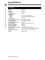
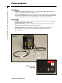
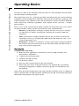
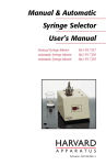
CO2/pH Controller
User's Manual
CO2 Gas/pH Controller MA1 70-2116
Publication 5405-001-REV-C
WEEE/RoHS Compliance Statement
EU Directives WEEE and RoHS
To Our Valued Customers:
We are committed to being a good corporate citizen. As part of that commitment,
we strive to maintain an environmentally conscious manufacturing operation. The
European Union (EU) has enacted two Directives, the first on product recycling
(Waste Electrical and Electronic Equipment, WEEE) and the second limiting the use
of certain substances (Restriction on the use of Hazardous Substances, RoHS).
Over time, these Directives will be implemented in the national laws of each EU
Member State.
Once the final national regulations have been put into place, recycling will be offered
for our products which are within the scope of the WEEE Directive. Products falling
under the scope of the WEEE Directive available for sale after August 13, 2005 will
be identified with a “wheelie bin” symbol.
Two Categories of products covered by the WEEE Directive are currently exempt
from the RoHS Directive – Category 8, medical devices (with the exception of
implanted or infected products) and Category 9, monitoring and control instruments.
Most of our products fall into either Category 8 or 9 and are currently exempt from
the RoHS Directive. We will continue to monitor the application of the RoHS
Directive to its products and will comply with any changes as they apply.
• Do Not Dispose Product with Municipal Waste
• Special Collection/Disposal Required
Table of Contents
Harvard Apparatus CO 2 /pH Controller User ’s Manual
1
SUBJECT
PAGE NO.
Warranty and Repair Information ........................2
Specifications ........................................................3
Unpacking ..............................................................4
Connections:
Plumbing ............................................................5
Electrical ............................................................5
Operating Basics:
Turning pH Controller On ..................................6
pH Probe Calibration ..........................................6
pH Set Point Configuration ................................6
Flow Control Configuration..............................6-7
Operation ............................................................7
Combination pH Electrode for Micro Wells ........8
Publication 5405-001-REV-C
Warranty and Repair Information
2
Harvard Apparatus CO 2 /pH Controller User ’s Manual
Serial Numbers
All inquires concerning our product should refer to the serial number of the unit.
Serial numbers are located on the rear of the chassis.
Calibrations
All electrical apparatus is calibrated at rated voltage and frequency.
W a rr a n t y
Harvard Apparatus warranties this instrument for a period of one year from date of
purchase.At its option, Harvard Apparatus will repair or replace the unit if it is found
to be defective as to workmanship or material.
This warranty does not extend to damage resulting from misuse, neglect or abuse, normal wear and tear, or accident.
This warranty extends only to the original customer purchaser.
IN NO EVENT SHALL HARVARD APPARATUS BE LIABLE FOR INCIDENTAL OR
CONSEQUENTIAL DAMAGES. Some states do not allow exclusion or limitation of
incidental or consequential damages so the above limitation or exclusion may not
apply to you. THERE ARE NO IMPLIED WARRANTIES OF MERCHANTABILITY,
OR FITNESS FOR A PARTICULAR USE, OR OF ANY OTHER NATURE. Some states
do not allow this limitation on an implied warranty, so the above limitation may not
apply to you.
If a defect arises within the two-year warranty period, promptly contact Harvard
Apparatus, 84 October Hill Road, Building 7, Holliston, Massachusetts
01746-1371 using our toll free number 1-800-272-2775. Goods will not be accepted
for return unless an RMA (returned materials authorization) number has been issued
by our customer service department. The customer is responsible for shipping
charges. Please allow a reasonable period of time for completion of repairs, replacement and return. If the unit is replaced, the replacement unit is covered only for the
remainder of the original warranty period dating from the purchase of the original
device.
This warranty gives you specific rights, and you may also have other rights which vary
from state to state.
R e p a i r F a c i l i t i e s a n d P a rt s
Harvard Apparatus stocks replacement and repair parts. When ordering, please
describe parts as completely as possible, preferably using our part numbers. If practical, enclose a sample or drawing.We offer a complete reconditioning service.
CAUTION
This pH controller is not registered with the FDA and is not for clinical use on human
patients.
CAUTION: Not for clinical use on human patients.
Publication 5405-001-REV-C
Specifications
Harvard Apparatus CO 2 /pH Controller User ’s Manual
3
Specifications
Range
Resolution
Accuracy
Input Resistance
Calibration:
Offset
Slope
CO2 Flowmeter
Gas Input/Output Connectors
pH Analog Output
Electrode Response Time
Electrode Slope
Electrode Impedance
Electrode Stability
Electrode Dimensions, L x D
System Power
Dimensions, H x W x D
Weight
Publication 5405-001-REV-C
0 to 14 pH
0.01 pH
±0.02 pH
1012 Ω
±2 pH through offset trimmer
80 to 110% through slope trimmer
2 L per min.
Quick disconnect fittings
BNC connector 4-20 mA
~0 sec
55 mV/pH in pH range of 1 to 14
200 MΩ
0.05 pH/day
1.5 x 0.03 in (38.1 x 0.75 mm)
12 VDC (Universal 90/240 VAC, 50/60 Hz adapter)
12.2 x 15.2 x 12.7 cm (4.8 x 6 x 5 in)
0.8 kg (1.75 lb)
Unpacking
Harvard Apparatus CO 2 /pH Controller User ’s Manual
4
Remove the pH controller and its components from the packing material. Inspect the
controller unit and components for damage. If any damage is found contact
Harvard Apparatus and do not use equipment unless otherwise specified by
Harvard Apparatus.
Y o u r p H C o n t ro l l e r S y s t e m I n c l u d e s :
•
(1) Controller unit
•
(1) Micro pH probe (69-0494)
•
(1) Twin axial BNC connector for analog out
•
(1) Output Hose 11⁄ 6” I.D. medical grade tubing
•
(1) AC/DC power adapter
•
(1) Power Cord
R e q u i re d f o r U s e :
Length of 18⁄ ” I.D. tubing to connect CO2 Gas source and CO2 Input on rear of the pH
controller unit.
Publication 5405-001-REV-C
Connections
5
Harvard Apparatus CO 2 /pH Controller User ’s Manual
Plumbing
•
CO2 In- CO2 input.This port requires a 18⁄ ” ID flexible tubing. Input pressure
source should be regulated to 10psi. Max.
•
CO2 Gas Output- This connection requires an output hose with a quick disconnect fitting (supplied with the unit).The output gas should be delivered directly
to the cell culture (this is best accomplished by using Harvard’s PDMI).
Electrical
•
12 VDC- The pH controller requires 12 VDC power. Use only the adapter provided with the pH controller unit.
•
pH Electrode Input- This is an isolated BNC connector that receives the
input signal from the micro pH probe (69-0494).
• Analog Out- This twin axial BNC connector carries the data out signal
(0 to 20 mA or 4 to 20 mA) for use with data acquisition system or
chart recorder.
CO2/pH Controller
Front View
CO2/pH Controller
Back View
Publication 5405-001-REV-C
Operating Basics
6
Harvard Apparatus CO 2 /pH Controller User ’s Manual
T u r n i n g p H C o n t ro l l e r O n
Make sure all connections have been properly made to the pH controller unit:
• 12 VDC connection
•
CO2 input hose
•
Analog Out cable (to recorder or other)
•
pH Electrode
•
CO2 output hose
Depress the “I” side of the switch on the rear of the pH controller unit.When the pH
controller is powered the “Power On” LED should illuminate.
p H P ro b e C a l i b r a t i o n
The CO2/pH Controller has been calibrated with an OFFSET for 7.0pH and a SLOPE for
4.0pH with a set up point of 6.50pH. Refer to the pH meter’s user manual (included)
for instructions on performing a 2-point or 3-point calibration.
R e q u i re d M a t e r i a l s f o r C a l i b r a t i o n
•
Three pH buffer solutions with pH of 4.0, 7.0, and 9.21.
The micro pH probe provided is extremely sensitive and should be calibrated daily to
ensure accurate readings. Due to the high sensitivity of the probe, electro static discharges can create false spikes in the pH readings. For best results use the probe in a
shielded environment and make sure that operator uses an anti-static discharge device
when ever possible.Another method to wrap the electrode probe with aluminum foil
(shield). If needed the aluminum foil can be grounded.
Electrostatic Discharge Mats
Anti Static Wrist Strap Kit
pH Set Point Configuration
This CO2/pH controller is a unilateral pH controller, which means that it only controls
pH in one direction, in this case it can only prevent the pH from becoming too basic.
With this controller, a pH set point can be entered; which will tell the pH controller
to prevent medium’s pH from rising above this set point by dosing and acid (carbon
dioxide). To learn how to configure a pH set point, refer to the pH meter’s user
manual (included).
F l o w C o n t ro l C o n f i g u r a t i o n
The flow control is located on the front of the pH controller. It determines the flow
rate at which the CO2 is delivered to the medium. Increasing the flow rate will reduce
the response time of the pH controller, and increase the pH overshoot of the controller. The overshoot of the pH controller is defined as the amount of pH that the
controller will reduce the medium’s pH, below that of the configured set point.
There will always be some overshoot that occurs when CO2 is delivered, because
Publication 5405-001-REV-C
Operating Basics
Harvard Apparatus CO 2 /pH Controller User ’s Manual
7
once the CO2 flow to the medium is shut off, some CO2 will still diffuse into the medium, thus further reducing the pH.
The desired flow rate for a particular medium will depend heavily on the buffering
capabilities of the medium itself. Mediums with weak basic buffering capabilities will
respond quickly to the addition of the acid and will have a larger overshoot. Mediums
with strong basic buffering capabilities will respond slower and have a smaller
pH overshoot.
There is also a flow control switch, which controls the internal gas flow valve. There
are three possible settings for this switch: Manual,Auto, and Momentary.
• Manual- (Up) Regardless of the pH set point the flow of CO2 gas is continuous.The flow rate will be controlled by adjusting the regulator (LED will
remain lit).
•
Auto- (Center) The CO2/pH controller will use the set point to activate the
on/off flow of CO2 gas automatically. (LED will lit only when the valve is activated and delivering CO2).
• Momentary- (Down) CO2 will flow as long as the switch is depressed.When
the switch is released it will return to the automatic mode (the LED will lit as
long as the switch is depressed).
Operation
Configuration and Setup
1. Make all of the appropriate connections to the CO2/pH controller unit.
(Power, Hoses and Probe)
2. Calibrate the micro pH probe.
3. Configure the pH set point.
4. Set the flow control.
5. Place the flow control switch in the Auto position.
6. Ensure that CO2 can be delivered directly to the medium.We recommend
using Harvard Apparatus’s PDMI to guarantee proper CO2 distribution over
the medium.
Other than the initial configuration and setup, the pH controller needs no additional
input to perform.The CO2/pH controller will monitor the pH and automatically make
adjustments depending on the pH set point.
Publication 5405-001-REV-C
Combination pH Electrode for Micro Wells
Harvard Apparatus CO 2 /pH Controller User ’s Manual
8
The pH electrode requires no external reference and it is designed to fit small perfusion chambers without effecting fluid exchange rate.
The electrode is pre-filled with reference solution (3M NaCl solution in 25% glycerol).
There is no need to refill the reference electrode. If the tip of the reference electrode
is blocked, open the luer cap and apply pressure to the luer port.The reference solution will appear at the tip (seen under a 10x magnification lens).
Fill the Tee fitting and put the luer cap back in its place.
Calibration
1. Connect the pH electrode to the BNC input of the pH meter.
2. Place the electrode tip in a pH 7.00 buffer and set the meter OFFSET to
pH 7.00
3. Rinse the electrode tip with distilled water.
4. Place the electrode tip in a pH 4.00 buffer and set the meter SLOPE to
pH 4.00
5. Place the electrode tip in the pH 7.00 buffer to confirm the settings.
One can choose the mV mode and plot the pH vs. the corresponding mV values.
This miniature combination pH/reference electrode has been designed to fit small
perfusion chambers without effecting fluid exchange rates. It does not require an
external reference electrode.The reference solution can be replaced.The electrode is
stored wet.
Specifications
Response Time
Slope
Impedance
Stability
Dimensions, L x D
~10 sec
55 mV/pH range of 1 to 14
200 MΩ
0.05 pH/day
1.5 x 0.03 in (38.1 x 0.75 mm)
Catalog No.
Product
BS4 69-0494
Combination pH Electrode for Micro Wells
Publication 5405-001-REV-C