1
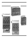
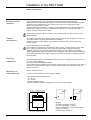
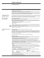
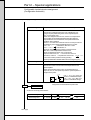
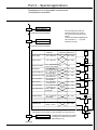
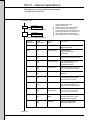
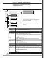
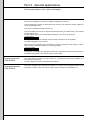
Installation of the RECTIVAR
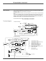
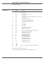
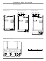
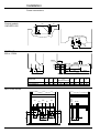
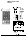
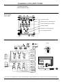
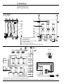
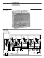
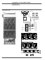
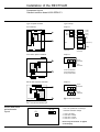
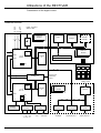
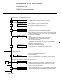
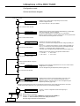
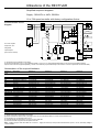
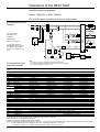
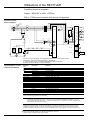
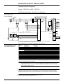
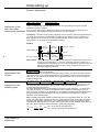
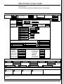
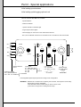
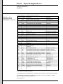
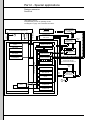
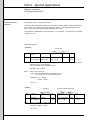
Component layout
RECTIVAR RTV-74
Power bridge
270 to 650A
AL1
AL2
AL3
5
2
3
V11
V14
3
V15
V13
V12
V16
4
V11
4
1
2
3
4
5
6
7
M1+
V15
V16
V12
2
6
M2-
V13
V14
5
7
1
6
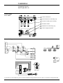
Resistance for 270A rating only
AL1
AL2
Current transformer
Thermocontact
Thyristor module (3 per controller)
Excitation rectifier
Control supply transformer
Fan connection terminals, ratings 400 and 650A (0 - 220)
AL3
M2-
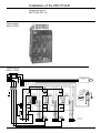
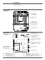
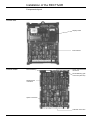
Internal wiring
TC3-2
TC2-2
TC1-2
J6
TC2
TC3
1
2
1
1
TC3-1
TC2-1
TC1-1
4
J3
1
J10
TC1
2
1
16
2
10
J11
J8
16
1
10
D
E
F
G
A
H
B
C
1
(1)
RV1
TH1
TH2
TH3
RH
RV2
V1
V2
1
J9
18
J5
1
F6 F5
G1
K1
G2
K2
G1
K1
G2
K2
G1
K1
G2
K2
F3 F1
1
F4
F2
18
J4
-
1
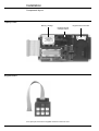
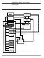
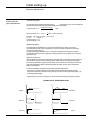
Cutting up of
power board
AL
AL
+
18
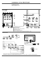
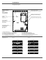
Ratings 400 and 650A : fans connected to terminals 0 - 220
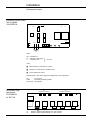
270A rating : for 220V short out the RH resistance using terminals 6 and 10 of the J11 connector of the power board.
1/26
M1+