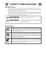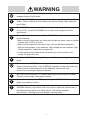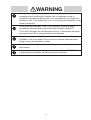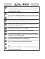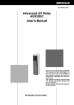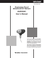
1
No. CP-SP-1181E
Explosion-Proof
Advanced UV Sensor
AUD500C
User's Manual
Thank you for purchasing the AUD500C.
This manual contains information for
ensuring the correct use of the
AUD500C. It also provides necessary
information for installation, maintenance, and troubleshooting.
This manual should be read by those
who design and maintain equipment
that uses the AUD500C. Be sure to keep
this manual nearby for handy reference.
RESTRICTIONS ON USE
This product has been developed, designed and manufactured in accordance with the
standards of explosion-protected electrical apparatus.
When using this product in application requiring particular safety, special care should
be taken to implement a fail-safe and/or redundant design concept as well as a periodic
maintenance program.
The notified body and/or the applicable standards may vary by the model number. Be
sure to confirm the specification for the details.
NOTICE
Ensure that this user's manual is provided to the user before the product is used.
Copying or duplicating this user's manual in part or in whole is forbidden. The information and specifications in this manual are subject to
change without notice.
Considerable effort has been made to ensure that this manual is free
from inaccuracies and omissions. If you should find any inaccuracies or
omissions, please contact Yamatake Corporation.
In no event is Yamatake Corporation liable to anyone for any indirect,
special or consequential damages as a result of using this product.
©2005 Yamatake Corporation ALL RIGHTS RESERVED
SAFETY PRECAUTIONS
■ About Icons
The safety precautions described in this manual are indicated by various icons.
Please be sure you read and understand the icons and their meanings described
below before reading the rest of the manual.
Safety precautions are intended to ensure the safe and correct use of this product, to prevent injury to the operator and others, and to prevent damage to property. Be sure to observe these safety precautions.
WARNING
CAUTION
Warnings are indicated when mishandling this product
might result in death or serious injury.
Cautions are indicated when mishandling this product
might result in minor injury to the user, or only physical
damage to the product.
■ Examples
Triangles warn the user of a possible danger that may be caused by
wrongful operation or misuse of this product. These icons graphically
represent the actual danger. (The example on the left warns the user of
the danger of electric shock.)
White circles with a diagonal bar notify the user that specific actions are
prohibited to prevent possible danger. These icons graphically represent
the actual prohibited action. (The example on the left notifies the user
that disassembly is prohibited.)
Filled-in black circles instruct the user to carry out a specific obligatory
action to prevent possible danger. These icons graphically represent the
actual action to be carried out. (The example on the left instructs the user
to remove the plug from the outlet.)
i
WARNING
Do not combine the AUD500C with a unit other than Yamatake's flame
safeguard control AUR series.
Install the AUD500C in accordance with the National Institute of Industrial
Safety "Factory Explosion-Proof Electrical Facilities Guide" (Gas explosionproof 1994).
The AUD500C has acquired certification as an explosion-proof housing
(Ex d IIC T4). Install the AUD500C at a location that complies with this
certification.
Take sufficient countermeasures if the AUD500C is installed in locations such
as the following:
• Near sources of ultraviolet rays other than the burner flame, such as red-hot
furnace walls (1370˚C or more)
• Near sources of gamma rays and x-rays, such as diffraction analyzers,
electron microscopes, x-ray machines, high-voltage vacuum switches, highvoltage capacitors, radioactive isotopes, etc.
• In atmospheres that interfere with ultraviolet rays, due to steam, soot,
smoke, oil spray, dust, etc.
Install the AUD500C at an angle that prevents it from detecting the ignition
spark.
Do not use the AUD500C where it might detect ultraviolet rays other than
those of the burner flame. If the AUD500C responds to other ultraviolet rays,
a flame failure in the burner will not be detected, and fuel will flow
continuously, causing an explosion hazard.
Be sure to turn the power OFF before removing or mounting the AUD500C.
Failure to do so might cause electric shock.
Be sure to turn the power OFF before wiring the AUD500C. Failure to do so
might cause electric shock.
To prevent an explosion, carry out the pilot turndown test carefully. If the
AUD500C detects a pilot flame that is too small to ignite the main burner, it
will determine that there is no flame failure. Fuel will be supplied
continuously, resulting in serious danger of an explosion.
ii
WARNING
When performing the pilot turndown test repeatedly, stop the equipment
completely every time the pilot turndown test is completed in order to
completely discharge the unburnt gas or oil accumulated in the combustion
chamber or flue. If the unburnt gas or oil is not discharged completely, it may
cause an explosion.
Do not touch the AUD500C or the F or G terminals of the AUR series
immediately after the power to the AUR series has been turned OFF.
The F and G terminals are still electrically alive for 1 minute after the power
has been turned OFF, causing an electric shock hazard.
When measuring the voltage between the F- and G-terminals of the
AUD500C in the wiring check, do not touch any terminal with bare hands.
Doing so may cause an electric shock.
Be sure to check wiring when the surrounding area is not an explosion-proof
environment.
Be sure to use only the packing gland that comes with the AUD500C. Use of
a different gland invalidates the explosion-proof certification.
iii
CAUTION
The AUD500C is specially designed for intermittent burner operation (system
is started and stopped once or more within 24 hours) and 24-hour continuous
burner operation (combustion continues for 24 hours or longer). An AUR
series device with a self-check function must be used as an amplifier in
combination with the AUD500C.
Do not install the AUD500C in locations where it is likely to be directly
exposed to certain chemicals or fumes (such as those containing ammonia,
sulfur, chlorine, or ethylene compounds; or acids and other corrosive gases).
Be sure to observe the ambient temperature indicated in the specifications.
Failure to do so may cause damage or malfunction.
Only authorized personnel who have technical skills with combustion
equipment and flame safeguard controls should carry out the mounting,
wiring, inspection, adjustment, and maintenance work.
If the AUD500C is operated in an atmosphere where any steam, smoke, oil
mist, dust, and/or organic solvents exist that interfere with ultraviolet rays,
take appropriate corrective measures.
When using multiple burners, mount the AUD500C in a position where it
detects only the flame of the burner to be monitored.
Carry out wiring work in conformity with the specified standards.
Always separate the signal cables of the AUD500C from the high voltage
cables of the ignition transformer and power cables, and then always run the
signal cables in a different conduit tube.
Do not reuse the packing gland. Doing so would jeopardize explosion-proof
performance due to degradation of the packing gland.
After the wiring work has been completed, always check that the wiring is
correct. Incorrect wiring may cause damage or malfunction.
Only authorized personnel who have technical skills with combustion
equipment and flame safeguard controls must carry out the pilot turndown
test.
The service life of the AUD10C tube unit built into the AUD500C is 3 years or
25,000 operation hours. To ensure operational safety, replace the tube unit
with a new one within this period.
iv
CAUTION
Do not transport the AUD500C while it is mounted on the combustion
equipment. Impact or vibration during transportation may cause the
AUD500C to malfunction. Before transporting, remove the AUD500C and
put it in its specially designed packing box.
Replace the AUD50A shutter unit with a new one approximately every 3
years.
v
Unpacking
Check the following items when removing the AUD500C from its package:
1. Check the model number to make sure you received the correct product.
2. Check for any obvious damage.
3. Check the contents of the package against the packing list to make sure that all items are included.
Handle the AUD500C and its accessories with care to prevent damage or loss of parts.
If there is any problem with your order, please contact your dealer immediately.
Name
Model No.
Q'ty
Remarks
Body
AUD500C
1
Chapter 7.
SPECIFICATION
User's Manual
CP-SP-1181E
1
This manual
Effective operation time
label
9735-001-00
1
●Effective operation time label
vi
The Role of This Manual
Seven different manuals are available for the AUD500C and the AUR series. Read them as necessary for your specific requirements. If a manual you require is not available, contact Yamatake Corporation or its dealer.
AUD500C Explosion-Proof Advanced UV Sensor
Manual No. CP-SP-1181E
This manual.
It describes the mounting, wiring, maintenance, inspection, and
troubleshooting of the AUD500C when it is used with combustion
equipment.
AUR300C Advanced UV Relay
Manual No. CP-SP-1142E
Personnel in charge of design, mounting, operation, and maintenance of
combustion equipment using the AUR300C should read this manual.
The manual describes the mounting, wiring, trial-run adjustment,
maintenance, and inspection of the AUR300C.
AUR350C Advanced UV Relay with Communications
Manual No. CP-SP-1175E
Personnel in charge of design, mounting, operation, and maintenance of
combustion equipment using the AUR350C should read this manual.
The manual describes the mounting, wiring, trial-run adjustment,
maintenance, and inspection of the AUR350C.
AUR400C/450C Flame Safeguard Control Dynamic Self Check Burner
Controller
Manual No. CP-SP-1196E
This manual should be read by personnel using the AUR400C/450C for the
first time, those in charge of designing combustion equipment that uses the
AUR400C/450C or designing the hardware for mounting the device in a control panel, and personnel performing maintenance.
The manual gives an overview of the product, its mounting and wiring for
connection to other equipment, its operation, trial-run adjustment, maintenance and inspection, and specifications.
vii
Contents
SAFETY PRECAUTIONS
The Role of This Manual
Conventions Used in This Manual
Chapter 1.
OVERVIEW
■
■
■
■
■
Chapter 2.
Overview • • • • • • • • • • • • • • • • • • • • • • • • • • • • • • • • • • • • • • • • • • • • • • • • • • • • • • • • • • • • • • • • • 1
Features • • • • • • • • • • • • • • • • • • • • • • • • • • • • • • • • • • • • • • • • • • • • • • • • • • • • • • • • • • • • • • • • • 1
Part names • • • • • • • • • • • • • • • • • • • • • • • • • • • • • • • • • • • • • • • • • • • • • • • • • • • • • • • • • • • • • • • 1
Model No. • • • • • • • • • • • • • • • • • • • • • • • • • • • • • • • • • • • • • • • • • • • • • • • • • • • • • • • • • • • • • • • • 2
Configuration • • • • • • • • • • • • • • • • • • • • • • • • • • • • • • • • • • • • • • • • • • • • • • • • • • • • • • • • • • • • 2
MOUNTING
■
■
■
■
■
Chapter 3.
Before mounting the AUD500C • • • • • • • • • • • • • • • • • • • • • • • • • • • • • • • • • • • • • • • • • • 4
Monitoring of burner flame• • • • • • • • • • • • • • • • • • • • • • • • • • • • • • • • • • • • • • • • • • • • • • • 4
Location • • • • • • • • • • • • • • • • • • • • • • • • • • • • • • • • • • • • • • • • • • • • • • • • • • • • • • • • • • • • • • • • • 5
Mounting positions • • • • • • • • • • • • • • • • • • • • • • • • • • • • • • • • • • • • • • • • • • • • • • • • • • • • • • 6
Mounting of monitoring pipe • • • • • • • • • • • • • • • • • • • • • • • • • • • • • • • • • • • • • • • • • • • • • 7
WIRING
■ Wiring diagram • • • • • • • • • • • • • • • • • • • • • • • • • • • • • • • • • • • • • • • • • • • • • • • • • • • • • • • • • 10
■ Wiring check • • • • • • • • • • • • • • • • • • • • • • • • • • • • • • • • • • • • • • • • • • • • • • • • • • • • • • • • • • • • 11
■ Grounding • • • • • • • • • • • • • • • • • • • • • • • • • • • • • • • • • • • • • • • • • • • • • • • • • • • • • • • • • • • • • • 12
Chapter 4.
ADJUSTMENT
■
■
■
■
■
■
Before measurement of flame voltage • • • • • • • • • • • • • • • • • • • • • • • • • • • • • • • • • • 13
Measurement of flame voltage • • • • • • • • • • • • • • • • • • • • • • • • • • • • • • • • • • • • • • • • • • 13
Pilot turndown test • • • • • • • • • • • • • • • • • • • • • • • • • • • • • • • • • • • • • • • • • • • • • • • • • • • • • 14
Ignition spark response test • • • • • • • • • • • • • • • • • • • • • • • • • • • • • • • • • • • • • • • • • • • • 15
Final mounting of monitoring pipe • • • • • • • • • • • • • • • • • • • • • • • • • • • • • • • • • • • • • • 15
Final inspection • • • • • • • • • • • • • • • • • • • • • • • • • • • • • • • • • • • • • • • • • • • • • • • • • • • • • • • • • 15
Chapter 5.
TROUBLESHOOTING
Chapter 6.
MAINTENANCE AND INSPECTION
■ Periodic inspection • • • • • • • • • • • • • • • • • • • • • • • • • • • • • • • • • • • • • • • • • • • • • • • • • • • • • 17
■ Replacement of the tube unit • • • • • • • • • • • • • • • • • • • • • • • • • • • • • • • • • • • • • • • • • • • 18
■ Replacement of the shutter unit • • • • • • • • • • • • • • • • • • • • • • • • • • • • • • • • • • • • • • • • 19
viii
Chapter 7.
SPECIFICATIONS
■ Specification • • • • • • • • • • • • • • • • • • • • • • • • • • • • • • • • • • • • • • • • • • • • • • • • • • • • • • • • • • • • 21
■ Dimensions • • • • • • • • • • • • • • • • • • • • • • • • • • • • • • • • • • • • • • • • • • • • • • • • • • • • • • • • • • • • • 22
Conventions Used in This Manual
The following conventions are used in this manual:
Handling Precautions:
Handling precautions are items that the user should pay attention to when
handling the AUD500C.
>> :
Note :
Notes indicate useful information that the user might benefit by knowing.
:
This indicates the item or page that the user is requested to refer to.
Indicates the result of an operation, details displayed on the personal computer or devices, or the state of a device after an operation.
ix
Chapter 1.
OVERVIEW
■ Overview
The AUD500C Explosion-Proof Advanced UV Sensor (hereafter referred to as
the AUD500C) is a flame detector designed to sense the ultraviolet radiation of an
oil or gas burner flame. The AUD500C is used in combination with the dedicated
Advanced UV Relay or Dynamic Self-Checking Burner Controller (hereafter
referred to as the AUR series). Any malfunction that has occurred in the UV
sensor or UV relay can be accurately detected by the continuous self-check
function of the built-in shutter driven by the relay, ensuring highly reliable
combustion safety control.
■ Features
• The AUD500C comforms to standards for explosion-proof housings (Ex d II C
T4).
• For a self-checking flame sensor, the AUD500C is compact and lightweight.
This ensures unrestricted burner mounting.
• The operating ambient temperature is 60°C and the protection structure is IP67.
This ensures excellent environment-proof performance.
• Vertical mounting is possible and the maximum wiring distance is 200m. This
ensures flexible installation.
• Maintenance parts such as the AUD10C tube unit and AUD50A shutter unit
can be handled as a single unit. This ensures easy replacement and
maintenance work.
■ Part names
● Main unit
Mounting threads
Tube unit (AUD10C2100)
Shutter unit (AUD50A2100)
Cover
Flange
Outside earth
screw
Explosion-proof
cable gland
Cable
● Tube unit (AUD10C2100)
1
Chapter 1. Overview
● Shutter unit (AUD50A2100)
■ Model No.
Model No.
Cable length
Additional features
Special treatment
AUD500C21010
3m
None
None
AUD500C2101D
3m
Inspection certificate provided
None
AUD500C21010T
3m
None
Tropicalization
AUD500C2101DT
3m
Inspection certificate provided
Tropicalization
AUD500C21110
10m
None
None
AUD500C2111D
10m
Inspection certificate provided
None
AUD500C21110T
10m
None
Tropicalization
AUD500C2111DT
10m
Inspection certificate provided
Tropicalization
■ Configuration
● Combined combustion safety controller
Model No.
AUR300C, AUR350C
AUR400C, AUR450C
Description
Advanced UV Relay
Dynamic Self-Checking Burner Controller
Model No.
81441151-001
Description
Adapter (G2-1/4→R1)
● Adapter
● Maintenance / optional parts
Model No.
AUD10C2100
AUD50A2100
2
Description
Tube unit
Shutter unit
Chapter 2.
MOUNTING
WARNING
Install the AUD500C in accordance with the National Institute of Industrial
Safety "Factory Explosion-Proof Electrical Facilities Guide" (Gas explosionproof 1994).
The AUD500C has acquired certification as an explosion-proof housing
(Exd II CT4). Install the AUD500C at a location that complies with this
certification.
Take sufficient countermeasures if the AUD500C is installed in locations such
as the following:
• Near sources of ultraviolet rays other than the burner flame, such as red-hot
furnace walls (1370˚C or more)
• Near sources of gamma rays and x-rays, such as diffraction analyzers,
electron microscopes, x-ray machines, high-voltage vacuum switches, highvoltage capacitors, radioactive isotopes, etc.
• In atmospheres that interfere with ultraviolet rays, due to steam, soot,
smoke, oil spray, dust, etc.
Install the AUD500C at an angle that prevents it from detecting the ignition
spark.
Be sure to turn the power OFF before removing or mounting the AUD500C.
Failure to do so might cause electric shock.
Do not use the AUD500C where it might detect ultraviolet rays other that
those of the burner flame. If the AUD500C responds to other ultraviolet rays,
a flame failure in the burner will not be detected, and fuel will flow
continuously, causing an explosion hazard.
CAUTION
Do not install the AUD500C in locations where it is likely to be directly
exposed to certain chemicals or fumes (such as those containing ammonia,
sulfur, chlorine, or ethylene compounds; or acids and other corrosive gases).
Be sure to observe the ambient temperature indicated in the specifications.
Failure to do so may cause damage or malfunction.
Only authorized personnel who have technical skills with combustion
equipment and flame safeguard controls should carry out the mounting,
wiring, inspection, adjustment, and maintenance work.
If the AUD500C is operated in an atmosphere where any steam, smoke, oil
mist, dust, and/or organic solvents exist that interfere with ultraviolet rays,
take appropriate corrective measures.
When using multiple burners, mount the AUD500C in a position where it
detects only the flame of the burner to be monitored.
3
Chapter 2. MOUNTING
■ Before mounting the AUD500C
• To mount the AUD500C correctly, thoroughly read the instruction manuals
published by burner, boiler, and/or other equipment manufacturers. Make the
proper mounting plan while referring to such instruction manuals.
• It is necessary that the AUD500C actually monitors the flame. As long as the
overall layout and temperature around the burner and other limitations permit,
mount the AUD500C as close to the flame as possible. The closer the
AUD500C is to the burner nozzle, the more ultraviolet radiation it will detect.
• Mount the AUD500C far from the ignition transformer. Mount the ignition
transformer as close to the burner as possible, and then ground it well.
■ Monitoring of burner flame
● Monitoring of pilot flame only (continuous pilot, intermittent pilot)
The main burner must be reliably ignited with the minimum pilot flame that the
AUD500C can detect. Therefore, throttle the pilot fuel manual valve until the
main burner barely ignites . Mount the AUD500C under these conditions so that
the AUD500C monitors only the top of the pilot flame. Put the monitoring area as
close to the top of the flame as possible so that the AUD500C monitors the pilot
flame along with the axis of the pilot flame.
● Monitoring of both pilot flame and main flame (continuous pilot, intermittent pilot)
Mount the AUD500C so that its line of sight intersects both the pilot flame and
the main flame.
● Monitoring of main flame only (interrupted pilot)
Mount the AUD500C so that the AUD500C monitors the main flame in any state
(the most stable part of the flame during both low combustion and high
combustion). In special combustion, where high combustion and low combustion
are mixed, the use of two units in order to monitor the main flame of each is
recommended.
● Multiple burners in one combustion chamber
Mount an AUD500C on each burner and carry out the mounting work so that
neither AUD500C detects the flame of the other burner incorrectly.
Additionally, the AUD10C tube unit of the AUD500C may produce an electrical
discharge phenomenon inside the tube. This electrical discharge may emit
ultraviolet rays from the tube. Therefore, when using multiple units, adjust their
positions so that no ultraviolet radiation from the other tube unit is detected.
4
Chapter 2. MOUNTING
● Redundant system (duplicate monitoring)
To avoid unnecessary shut off as much as possible and increase the reliability of
the system, we recommend duplicate monitoring. Make a redundant system using
two AUD500C's to monitor the burner flame. If either AUR series device does
not output a flame signal or if a false signal exists, an alarm signal is output but
combustion continues. If both AUR series devices detect a flame failure at the
same time, the system is shut off. This method prevents unnecessary shutoff
resulting from flame fluctuation or from the failure of the AUD500C or the
combustion safety controller.
■ Location
Determine the optimal mounting location of the AUD500C while carefully
observing the following items:
● Temperature
Mount the AUD500C in a place where the operating temperature range is -20°C
to +60°C.
Handling Precautions
• If the above temperature range is not observed, the AUD10C tube
unit or AUD50A shutter unit components of the AUD500C may
malfunction or shut off unnecessarily.
• If the actual temperature may exceed the operating temperature
range, put an appropriate thermal insulation plate between the
combustion chamber and the AUD500C or carry out air purging to put
the temperature within the operating temperature range.
● Vibration
Mount the AUD500C in a place where the acceleration is 4.9 m/s2 or less.
Handling Precautions
• Vibration may cause the service life of the AUD10C tube unit or
AUD50A shutter unit to be shortened, or may cause improper
operation or malfunction.
● Outdoors
Provide the AUD500C with protection from the rain.
Handling Precautions
• The surface color of the case may change due to the influence of
sunshine or other causes. However, this will not affect the functioning
of the product.
5
Chapter 2. MOUNTING
■ Mounting positions
Mount the AUD500C so that its explosion-proof cable gland points downward.
Do not rotate
the AUD500C
in this plane.
In mounting, do not
rotate the AUD500C
in this plane.
Explosion-proof cable gland
Vertical plane
Handling Precautions
• If the AUD500C is wrongly mounted, the shutter of the AUD50A
shutter unit may be damaged or malfunction.
From a side view the allowable rotation ranges from an upper limit of 90°
(explosion-proof cable gland is horizontal) to a lower limit of 45°.
Upper limit 90°
90°
Horizontal
plane
45°
Vertical
plane
Lower limit 45°
6
Explosion-proof cable gland
Chapter 2. MOUNTING
■ Mounting of monitoring pipe
● Monitoring pipe materials
Use a monitoring pipe with a black inside wall. If a pipe with a stainless steel or
galvanized inside wall is used, diffused reflection of the ultraviolet rays occurs
inside the pipe, causing malfunction.
● Size of monitoring pipe
To detect the ultraviolet radiation of the flame at its optimal level, it is necessary
to widen the light-receiving area of the AUD500C. If a recommended flame
voltage of 1.5V or more cannot be maintained, make the monitoring pipe wider so
that it receives a sufficient amount of ultraviolet radiation.
• Use a monitoring pipe as large as possible and connect the pipe to the
AUD500C with the reducer.
• Make the length of the monitoring pipe as short as possible. However, always
keep the operating ambient temperature within 60°C.
● Mounting space
Keep a sufficient space to allow easy maintenance, inspection, and service work.
Adapter*
Monitoring pipe,
25A or more
(Use 2B to 3B pipe.)
Reducer
Furnace wall
Air
Union pipe
joint
Tapered monitoring hole
Connection
nipple (1B)
Welding
Burner
Plate
*If air purging is needed, supply air through the air-purge pipe (R1/8) of the adapter.
Handling Precautions
• Mount the AUD500C so that it monitors the burner at an angle from
above. If the AUD500C is mounted so that it monitors the burner at
an angle from below or in the same horizontal plane, dust or soot may
accumulate on the monitoring window or in the monitoring pipe. This
may block the ultraviolet rays, so that the flame is not detected.
• Mount the AUD500C so that its monitoring direction intersects the
flame axis at as small an angle as possible. This ensures a wide
overlap of the AUD500C's monitoring area and the flame. Thus, the
amount of ultraviolet radiation that is detected is maximized.
7
Chapter 2. MOUNTING
Correct
Depth of flame when checked at an acute angle
Unburnt fuel
Burner
Incorrect
Depth of flame is small
● Temporary welding for positioning of monitoring pipe
(1) Prepare the monitoring pipe and make the mounting hole
• Make the mounting hole for the monitoring pipe at the selected monitoring
pipe mounting location.
• Screw in one end of the monitoring pipe and cut the monitoring pipe to a
desired length so that its length is as short as possible.
(2) Weld the monitoring pipe temporarily
• Weld the monitoring pipe temporarily to the plate of the combustion
chamber, of the boiler (etc.). At this time, do not weld the monitoring pipe
completely since inspection and adjustment are required for the flame to be
detected properly.
Monitoring pipe
Weld these parts temporarily.
Furnace wall
(refractory material)
Plate
(3) Mount the AUD500C
• Attach the conversion adapter to the AUD500C mounting threads. The
recommended tightening torque is 12 to 18N•m.
• Mount the AUD500C so that its cable gland faces downward, using a union
pipe joint or the like.
(4) Purging of monitoring pipe air
• Attach an air-purge pipe (R1/8) after removing the adapter plug. To do an air
purge, make the internal pressure of the conversion adapter higher than the
internal pressure of the furnace.
Note
• Air purging of the inside of the monitoring pipe is useful for cooling the
AUD500C and keeping the monitoring area clean. In particular, if the
ambient temperature of the AUD500C exceeds 60°C, cooling, such as by air
purging, is needed.
8
Chapter 3.
WIRING
WARNING
Install the AUD500C in accordance with the National Institute of Industrial
Safety "Factory Explosion-Proof Electrical Facilities Guide" (Gas explosionproof 1994).
Be sure to turn the power OFF before wiring the AUD500C. Failure to do so
might cause electric shock.
Be sure to use only the packing gland that comes with the AUD500C. Use of
a different gland may invalidate the explosion-proof certification.
When measuring the voltage between the F and G terminals of the AUD500C
in the wiring check, do not touch any terminal with bare hands. Doing so may
cause an electric shock.
Be sure to check wiring when the surrounding area is not an explosion-proof
environment.
CAUTION
Only authorized personnel who have technical skills with combustion
equipment and flame safeguard controls should carry out the mounting,
wiring, inspection, adjustment, and maintenance work.
Always separate the signal cables of the AUD500C from the high voltage
cables of the ignition transformer and power cables, and then always run the
signal cables in a different conduit tube.
Do not reuse the packing gland. Doing so would jeopardize explosion-proof
performance due to degradation of the packing gland.
9
Chapter 3. WIRING
■ Wiring diagram
Advanced UV Sensor
AUD500C
AUR series
Earth
Blue
Yellow
White
White
(F)
(G)
Shutter
Shutter
When performing the wiring work, put all lead wires used for the connection with
the AUR series in a conduit tube or conduit box. Additionally, run these lead
wires separately from other power cables.
Handling Precautions
• Never run the lead wires to the AUD500C in the same conduit tube
that contains high-voltage cables, such as power cables or ignition
transformer cables.
• Put the high-voltage cables of the ignition transformer and the
grounding cables in the same conduit tube. Ground one end of this
conduit tube well. In particular, this caution must be observed strictly
when using an automotive spark plug.
• If the surge of the ignition transformer adversely affects the
AUD500C, ground both ends of the conduit tube between the
AUD500C and combustion safety control unit or change the cable
routing.
10
Chapter 3. WIRING
■ Wiring check
WARNING
Do not use the AUD500C where it might detect ultraviolet rays other than
those of the burner flame. If the AUD500C responds to other ultraviolet rays,
a flame failure in the burner will not be detected, and fuel will flow
continuously, causing an explosion hazard.
Before applying voltage to the AUD500C, check that the wiring is correct.
Procedures
(1) In the relay box, disconnect the blue and yellow lead wires that come from the
AUD500C.
(2) Turn ON the power to the AUR series.
(3) Measure the DC voltage between the F and G terminals with a multimeter or
digital voltmeter.
(4) Connect the positive probe to the G terminal (yellow lead wire) and the
negative probe to the F terminal (blue lead wire).
>> If a voltage of 160Vdc to 220Vdc is output, the wiring work has been
performed correctly. If the measured DC voltage is a negative value, the
wiring to the F and G terminals is reversed.
(5) Next, measure the DC voltage between the shutter voltage S1 and S2 terminals
(both are white lead wires).
Handling Precautions
• The polarity of the S1 and S2 terminals is not specified. When
measuring the voltage with an analog multimeter, in order to check
the polarities, set a large voltage range so that the indication needle
does not deflect over the negative scale. After that, measure the
shutter voltage.
>> If the shutter voltage changes in a range of 15Vdc to 24Vdc *, the wiring is
connected correctly. If the shutter voltage of the multimeter shows 24Vdc
constantly or if it shows 0V, the wiring may be incorrect.
* If a flame exists, the shutter voltage changes within a range of 0Vdc to
24Vdc.
(6) Re-connect the lead wires 1 minute or longer after the power to the AUR unit
has been turned OFF.
Handling Precautions
• Because the F and G terminals are still electrically live for 1 minute
after the power has been turned off, touching them within that time is
an electric shock hazard.
11
Chapter 3. WIRING
■ Grounding
Be sure to check that the wiring is correct before turning the power on.
(1) Grounding with a direct connection to an outside earth terminal.
(2) Grounding by connecting an outside earth terminal to the ground terminal of
the relay box.
Relay box
12
Chapter 4.
ADJUSTMENT
■ Before measurement of flame voltage
Before measuring the flame voltage, check the operation of the AUD500C
through the flame voltage output terminals of the AUR series.
Multimeter or voltmeter
AUR series
*
Black
*
Red
+
0Vdc to 10Vdc range
Input impedance:
100 kΩ or more
* Check the terminal numbers in the
AUR series user's manual.
(1) Connect a multimeter to the (+) and (-) terminals of the AUR series.
(2) Light a lighter in front of the AUD500C's ultraviolet ray sensing tube to check
that the voltage is output correctly.
Handling Precautions
• When using a flame, check that there is no flammable gas around the
AUD500C.
■ Measurement of flame voltage
If both pilot flame and main flame exist, measure each flame voltage.
Additionally, measure the flame voltage in the maximum combustion and
minimum combustion states.
(1) Mount the AUD500C on the monitoring pipe temporarily.
(2) Start the combustion of the burner.
(3) To determine an optimal monitoring position, measure the flame voltage
between the (+) and (-) terminals of the AUR series with a multimeter while
moving the monitoring pipe position little by little in order to find the position
where the voltage is as highly stable as possible.
Recommended flame voltage
1.5Vdc or more
(The flame voltage may fluctuate in a
range of 0.1 to 0.3V synchronized with
the shutter operation of the AUD500C.)
Items to inspect
• Check that the flame is monitored
correctly.
• Check that the light-receiving lens of
the AUD500C is not duty.
• Check that foreign matter such as
soot has not accumulated in the
monitoring pipe.
13
Chapter 4. ADJUSTMENT
■ Pilot turndown test
This test is intended to check that the flame correctly ignites the main burner when
the AUD500C detects a pilot flame, if the gas pressure and air pressure change to
their worst possible conditions.
WARNING
To prevent an explosion, carry out the pilot turndown test carefully. If the
AUD500C detects a pilot flame, that is too small to ignite the main burner, it
will determine that there is no flame failure. Fuel will be supplied
continuously, resulting in serious danger of an explosion.
When performing the pilot turndown test repeatedly, stop the equipment
completely every time the pilot turndown test is completed in order to
completely discharge the unburnt gas or oil accumulated in the combustion
chamber or flue. If the unburnt gas or oil is not discharged completely, it may
cause an explosion.
CAUTION
Only authorized personnel who have technical skills with combustion
equipment and flame safeguard controls should carry out the mounting,
wiring, inspection, adjustment, and maintenance work.
Only authorized personnel who have technical skills with combustion
equipment and flame safeguard controls should carry out the pilot turndown
test.
For details about how to carry out the pilot turndown test, refer to the user's
manual for the AUR series used with the AUD500C, as well as the instruction
manuals published by equipment manufacturers.
14
Chapter 4. ADJUSTMENT
■ Ignition spark response test
WARNING
Do not use the AUD500C where it might detect ultraviolet rays other than
those of the burner flame. If the AUD500C responds to other ultraviolet rays,
a flame failure in the burner will not be detected, and fuel will flow
continuously, causing an explosion hazard.
● Procedures
(1) Close the manual shut-off valves of the pilot burner and main burner.
(2) Operate the burner so that it ignites. When the ignition spark occurs, check
that the flame relay (K2) of the AUR series is not energized.
(3) If the flame relay is energized, adjust the monitoring point of the AUD500C to
avoid the influence of the ignition spark and its reflection.
Handling Precautions
• The following shows various sources other than flame, that may
activate the AUD500C. Check that the AUD500C's operation is not
influenced by these sources under any operating conditions.
Examples:
Ultraviolet ray
sources
Gamma ray and
X-ray sources
Red-hot furnace walls (1370°C or more, within 50cm of
furnace wall)
Ignition transformer and welding arc spark
Gas laser
Sunlamps
Disinfecting lamps, ultraviolet ray radiation lamps, fluorescent
lamps
Strong flashlight (toward UV sensor)
Diffraction analyzer
Electron microscope
X-ray cameras
High-voltage vacuum switches
High-voltage capacitors
Radioactive isotope
Other sources producing ultraviolet rays, gamma rays, and
X-rays
■ Final mounting of monitoring pipe
(1) When the equipment is operating properly with the specified flame voltage
output after all adjustments have been completed correctly, turn OFF the power
to the equipment, remove the AUD500C, and weld the monitoring pipe
permanently.
(2) Mount the AUD500C on the monitoring pipe securely and perform the final
wiring.
■ Final inspection
To control the burner properly, perform at least one cycle operation of the
equipment to check that all control operations function correctly.
15
Chapter 5.
TROUBLESHOOTING
WARNING
Be sure to turn the power OFF before removing or mounting the AUD500C.
Failure to do so might cause electric shock.
Do not touch the AUD500C or the F or G terminals of the AUR unit
immediately after the power to the AUR unit has been turned OFF.
The F and G terminals are still electrically alive for 1 minute after the power
has been turned OFF, posing an electric shock hazard.
CAUTION
Only authorized personnel who have technical skills with combustion
equipment and flame safeguard controls should carry out the mounting,
wiring, inspection, adjustment, and maintenance work.
● Tools and parts to be prepared
• Multimeter
DC range: 0 to 10V, 0 to 30V, 0 to 300V
• For details about replacement parts, refer to
● Maintenance / optional parts (on page 2).
● Troubleshooting procedures
(1) Check the following conditions.
Item
Power voltage
•
•
•
•
•
•
•
•
•
Wiring
Ambient temperature
Ambient humidity
Operation
Check that the power switch is turned ON correctly.
Check for loose power terminals.
Check that the voltage is within the allowable range.
Check that the terminal number is correct.
Check for faulty wiring.
Check the insulation for deterioration or damage.
Check that the temperature is +60°C or less.
Check that the ambient humidity is 90% RH or less.
Check that no dew condensation occurs inside the AUD500C.
(2) Check the AUD500C according to the flowchart below.
Check the
flame voltage.*1
Zero
OK
Remove the AUD10C.
Does the
shutter open
when power is supplied
to the AUR?
Small
• Clean the monitoring window.
• Clean the inside of the monitoring pipe.
Correct
Check the
flame voltage.*1
NO (closed)
NG
Adjust the monitoring
position and/or burner.
OK
Correct
YES (open)
Check the
voltage between the
F and G terminals.*2
NG
OK
Replace the
AUD10C.
16
Check the
shutter voltage.*3
NG
OK
Check the wiring
and replace the
AUR unit.
Replace the
AUD50A.
Check the wiring
and replace the
AUR unit.
*1: Normal when 1.5Vdc or more
*2: Normal when 160 to 220Vdc
*3: Normal when fluctuating between 0 or 15 to 24Vdc
Chapter 6.
MAINTENANCE AND INSPECTION
WARNING
Be sure to turn the power OFF before removing or mounting the AUD500C.
Failure to do so might cause electric shock.
Do not touch the AUD500C or the F or G terminals of the AUR series
immediately after the power to the AUR unit has been turned OFF.
The F and G terminals are still electrically alive for 1 minute after the power
has been turned OFF, causing an electric shock hazard.
CAUTION
Only authorized personnel who have technical skills with combustion
equipment and flame safeguard controls should carry out the mounting,
wiring, inspection, adjustment, and maintenance work.
The service life of the AUD10C tube unit built-into the AUD500C is 3 years or
25,000 operation hours. To ensure operational safety, replace the tube unit
with a new one within this period.
■ Periodic inspection
(1) Turn OFF the power to the AUR unit.
(2) Clean the monitoring window and monitoring pipe periodically.
Remove the AUD500C from the monitoring pipe, and clean the inside of the
monitoring pipe and/or the lens with a cloth rag.
(3) To check the operation of the AUD10C tube unit, perform a safety shutoff test
periodically.
For details about safety shutoff test, refer to
the user's manual for the AUR300C, No. CP-SP-1142E.
user's manual for the AUR350C, No. CP-SP-1175E.
(4) Adjust the burner so that it operates at the optimal operating level
recommended by the burner manufacturer.
● Frequency of maintenance and inspection
Inspection contents
Check for fouling of monitoring window and monitoring
pipe, and loose screws
Safety shutoff test
Measurement of flame voltage
Pilot turndown test
Inspection frequency
Once a month or more
Once a month or more
Once a month or more
Once a year or more
Handling Precautions
• If unexpected burner shutoff may cause a serious damage, perform the
inspection more frequently.
• If the burner manufacturer provides specific instructions about
maintenance and inspection, always strictly observe them.
17
Chapter 6. MAINTENANCE AND INSPECTION
■ Replacement of the tube unit
(1) Turn OFF the power.
(2) After 1 minute or more, loosen the cover setscrew, rotate the cover, and
remove it.
(3) Remove the 2 tube-unit fixing screws on the rear of the tube unit.
(4) Hold the rear of the tube unit and gently raise it upward to remove it.
(5) Insert a new tube unit into the top of the shutter unit and push the back of the
tube unit down to install it.
(6) Tighten the 2 tube-unit fixing screws.
(7) Make sure that the O-ring has not disengaged from the flange unit.
(8) Tighten the cover firmly, and then tighten the cover setscrew.
O-ring
Mounting threads
Tube unit
Tube-unit fixing screws (2)
Shutter unit
Cover setscrew
(width across flat: 2mm)
Flange
Handling Precautions
• The tube unit has polarity. Match the polarity with the polarity indication
labels F and G on the upper portion of the shutter unit and mount it
correctly. Additionally, there is a height difference on the shutter unit
corresponds to the tube unit. The tube unit is designed so that it cannot
that be mounted the wrong way. Do not attempt to forcibly mount the
tube unit in the reverse direction.
• When transporting or storing the tube unit, always put it in its specially
designed packing box.
• If the thermo-label pasted on the AUD10C has turned black (no longer
white), the temperature has probably exceeded the allowable operating
temperature range. If the advanced UV senser is operating where
ambient temperature is excessive, cool the AUD500C using air purging.
The thermo-label should be regarded as a reference only. Always
confirm the correct ambient temperature with a thermometer.
• When putting the cover on, mount the O-ring of the flange unit securely.
Failure to do so may cause lower sealing ability.
• Tighten the terminal screws and cover setscrew with a torque of 1.5N·m.
18
Chapter 6. MAINTEANCE AND INSPECTION
■ Replacement of the shutter unit
CAUTION
Replace the AUD50A shutter unit with a new one approximately every 3
years.
(1) Turn OFF the power.
(2) Loosen the cover setscrew, rotate the cover, and remove it.
(3) Remove the 4 terminal screws (2 white lead wires, 1 blue lead wire, 1 yellow
lead wire) to disconnect the lead wires from the shutter unit.
(4) Remove the 2 shutter-unit fixing screws.
(5) Remove the shutter unit from the flange.
(6) Remove the tube unit from the shutter unit. For details, refer to the previous
section,
■ Replacement of tube unit (on page 18).
(7) Secure a new shutter unit to the flange unit.
Shutter unit
fixing screws (2)
Tube unit
fixing screws (2)
Tube unit
Shutter unit
F terminal (blue lead wire)
G terminal (yellow lead wire)
White lead wires
G terminal,
yellow lead wire
F terminal,
blue lead wire
Bottom view
19
Chapter 6. MAINTENANCE AND INSPECTION
(8) Connect the lead wires to the 4 terminals on the shutter unit correctly.
Handling Precautions
• Connect the blue lead wire to the F terminal and the yellow lead wire
to the G terminal. Connect the signal wires so that they are matched
with the polarity indication labels F and G on the shutter unit.
(9) Mount the tube unit.
(10) Subsequent procedures are the same as those after step (6) stated in the
previous section, ■ Replacement of tube unit.
Handling Precautions
• Tighten the terminal screws and cover setscrew with a tightening torque
of 1.5N·m.
20
Chapter 7.
SPECIFICATIONS
■ Specification
Item
Applicable types of flame*
Description
City gas, natural gas, propane gas, kerosene, heavy oil, coke oven gas,
hydrogen, chlorine, ammonia, naphtha, ethylene, etc.
Self-checking cycle
Approx. 75 cycles/ min
Insulation resistance
Between flange mounting part and F-terminal (or blue lead wire),
between flange mounting part and G-terminal (or yellow lead wire),
between flange mounting part and S1-terminal (or white lead wire),
between flange mounting part and S2-terminal (or white lead wire):
50MΩ min. by 500Vdc megger at each of the above locations.
(The tube unit AUD10 must be removed.)
Dielectric strength
Between flange mounting part and F-terminal (or blue lead wire),
between flange mounting part and G-terminal (or yellow lead wire),
between flange mounting part and S1-terminal (or white lead wire),
between flange mounting part and S2-terminal (or white lead wire):
1500Vac for 1min or 1800Vac for 1s at each of the above locations.
(The tube unit AUD10 must be removed.)
Ambient temperature
–20 to +60°C
Ambient storage temperature
–20 to +70°C
Ambient storage humidity
90% RH at 45°C max. (no condensation allowed)
Vibration resistance
4.9m/s2 max., 10 to 55Hz for 2 hours each in X, Y and Z directions
Pressure resistance for mounting part 690kPa
Protection
IP67
Mounting positions
–45° to +90° (in side view)
Mounting (on the monitoring pipe)
Flange:
Parallel pipe thread G2-1/4
Conversion adapter: Taper pipe thread R1
Lead wires
AWG18 heat-resistant silicone cables (4 cores)
Flame signal wire requirements and IV wires with 2.0 mm2 and max. 200m in length.
extension distance
Material
Aluminum
Color
Purple (equivalent to DIC257)
Mass
Approx. 2.5kg
Explosion-proof housing
Ex d IIC T4
Certified number
TIIS: TC17035
NEPSI: GYJ06241
Tube unit effective operation time
Under 3 years or 25,000 hours of operation time
* Ultraviolet ray quantity differs according to the type of fuel. Also, the calorific value of the burner, type of
equipment, and installation conditions will have an influence.
21
Chapter 7. SPECIFICATION
■ Dimensions
Unit: mm
● Main body
Cover setscrew
(width across flat:2)
G2-1/4
Name plate
.
185
103dia.
24.5
dia
124
103
35
Outside earth screw M4
52.8
119.2
189
32
G 1/2
35
● Adapter assembly
(210)
22
Adapter
(for air purge)
74
R1
9
.
dia
80
Plug with hexagon socket (width across flat: 5)
2 points
2-R1/8
AUD500
Packing
54
17
75.5
Handling Precautions
• Tighten the adapter to the AUD500C with a tightening torque of 12 to
18N•m. If the torque is less than 12N•m the AUD500C will not be
properly sealed.
22
Revision History
Printed date Manual Number
Edition
Revised pages
Feb. 2005 CP-SP-1181E 1st Edition
July 2006
2nd Edition 1,2,21
5
21
Description
Model No. changed.
●Outdoors added.
Certified number of NEPSI added.
Specifications are subject to change without notice.
Advanced Automation Company
1-12-2 Kawana Fujisawa
Kanagawa 251-8522 Japan
URL: http://www.yamatake.com
Printed on recycled paper.
(05)
Printed in Japan.
1st Edition: Issued in Feb. 2005 (E)
2nd Edition: Issued in July 2006 (U)