1
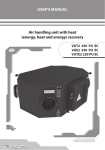
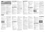
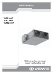
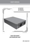
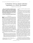
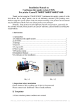
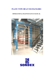
User’s Manual
Heat (Energy / Heat and Energy) Recovery Air-Handling
Unit
VUT2 250 P EC
VUE2 250 P EC
VUTE2 250 P EC
2
VU..2 250 P ЕС
Contents
Safety requirements
3
Introduction
5
Use
5
Delivery set
5
Designation key
6
Main technical data
6
Unit design and operating logic
8
Mounting and set-up
9
Condensate drainage
9
Connection to power mains
10
Unit control
11
Technical Maintenance
15
Fault handling
17
Storage and transportation rules
18
Manufacturer's warranty
18
Acceptance certificate
20
Seller information
20
Connection certificate
20
Warranty card
21
3
Safety requirements
• Read the user’s manual carefully prior to installing and operating the heat (energy / heat and energy)
recovery air-handling unit (hereinafter «Unit»).
• Fulfil the operation manual requirements as well as the provisions of all the applicable local and
national construction, electrical and technical codes and standards.
• The warnings contained in the user’s manual must be considered most seriously since they contain
vital personal safety information.
• Failure to follow the safety regulations may result in an injury or unit damage.
• Read the manual carefully and keep it as long as you use the unit.
• While transferring the unit control the user’s manual must be turned over to the receiving operator.
The symbols used in the present user’s manual have the following meaning:
WARNING!
DO NOT!
UNIT MOUNTING SAFETY PRECAUTIONS
The
unit
must
be
disconnected from the power
mains prior to installation or
repair.
The unit must be
grounded!
The unit must not be
operated
outside
the
temperature range stated
in the user's manual and
in aggressive or explosive
environments.
Do not use damaged
equipment or conductors
to connect the unit to the
power mains.
While installing the unit
follow the safety regulations
specific to the use of electric
tools.
Unpack the unit with care.
Do not change the power
cable length at your own
discretion.
Do not bend the power
cable.
Avoid damaging the power
cable.
Do not position any
heating devices or other
equipment
in
close
proximity to the unit
power cable.
4
VU..2 250 P ЕС
Safety precautions to be followed while operating the unit.
Do not wash the unit
with water.
Avoid penetration of
water onto the electric
parts of the unit.
Do not touch the unit
controls with wet hands.
Do not carry out the unit
maintenance with wet hands.
Use the unit only as originally
intended.
Do not connect any drying
machines or other similar
equipment to the unit and
the ventilation circuit.
Do not put any water
containers (e.g. vases
etc.) on top of the unit.
ON
Do not sit on the unit or put
any foreign objects on top
of it.
OFF
Disconnect the unit
from the power mains
prior to any technical
maintenance.
Do not let children operate
the unit.
Avoid damaging the
power
cable
while
operating the unit.
Do not put any foreign
objects on top of the
power cable.
Do not store any flammable
gases or highly flammable
substances in close proximity
to the unit.
Do not open the unit
during operation.
Should the unit generate
any unusual sounds, smell of
smoke disconnect it from the
power mains and contact the
service centre.
In case of prolonged
operation check the unit
from time to time for any
looseness which may
develop in the fasteners.
Do not shut off the air duct
during the unit operation.
Do not direct the air
stream produced by
the unit onto any
combustion appliances
or burning candles.
5
Introduction
The present user’s manual consisting of the technical details, operating instructions and technical
specification applies to the installation and mounting the VU__2 250 P EC heat (energy / heat and
energy) recovery air-handling unit (hereinafter «Unit»).
Use
Due to the ability to reduce heat/energy losses by means of recycling heat (energy / heat and
energy) recovery air-handling units have become an important element of energy-efficient spaces.
Being a component unit, the air-handling unit may not be commissioned for standalone operation.
The unit is designed to ensure continuous mechanical air exchange in houses, offices, hotels,
cafes, conference halls and other utility and public spaces as well as to recover the heat energy
contained in the air extracted from the premises to warm up the filtered stream of supply air.
The unit is designed for extended periods of continuous operation without disconnection from
the power mains.
The transported air must not contain flammable or explosive mixtures, chemically active vapours,
coarse dust, soot, fats or environments favourable for the formation of hazardous substances (toxic
substances, dust, pathogenic germs), sticky substances and fibrous materials.
The unit is not intended for operation by children or persons
with reduced physical, mental or sensory capacities, or lacking the
appropriate training.
The unit must be handled only by properly qualified personnel
after the appropriate briefing.
The choice of unit installation location must prevent
unauthorized access by unattended children.
Delivery set
Unit User’s manual
Packing box
Control panel - 1 item.;
- 1 item.;
- 1 item.;
- 1 item.;
6
VU..2 250 P ЕС
Designation key
VUT 2 250 P EC
Motor Type
Electronically commutated (EC)
Design features
P - suspended mounting
Air capacity, m³/h
Number of heat exchangers, pcs
Unit Type
VUT - Heat Recovery Ventilation
VUE - Energy Recovery Ventilation;
VUTE - Energy and Heat Recovery Ventilation.
Main technical data
370
46*
518
250
766
63
46*
211
ø124
ø12
864
* - Only for VUT2 250 P EC and VUTE2 250 P EC units.
Fig. 1. Outside and connecting dimensions of the unit
7
The air-handling units are intended for operation in closed spaces under ambient air temperatures
from +1 ºC to +60 ºC and relative humidity up to 80%.
Hazardous parts access and water ingress protection rating:
IP 44 for the unit motors;
IP 22 for the assembled unit connected to the air ducts.
The unit series designations, the main outside and connecting dimensions of the unit as well as
its appearance and technical parameters are given in Figure 1 and in Table 1.
The unit design is regularly improved, so some models can slightly differ from those ones
described in this manual.
Table 1 . Unit Technical Parameters
VUT2 250 P EC
VUE2 250 P EC
VUTE2 250 P EC
Model
Unit voltage [V /50-60 Hz]
1 ~ 230
Maximum fan power, [W]
125
Fan current, [A]
0,87
Max. air capacity [m3/h]
257
RPM
2930
Sound pressure level at 3 m distance [dB(A)]
Max. transported air temperature [°C]
Casing material
39
from -25 up to +60
aluzinc
Insulation
polypropylene foam, 10 mm
Filter: air exhaust/air supply
G4 bag filter
(SFK VUT2 200-250 P/P EC G4)
Connected air duct diameter [mm]
Heat recovery efficiency [%]
Heat exchanger type
Ø 125
up to 89
cross flow, 2 items
8
VU..2 250 P ЕС
Unit design and operating logic
The unit operating logic is illustrated in Fig. 2. The warm stale air from indoors is supplied into the
unit where it undergoes filtration. The filtered air is directed into the heat exchangers and extracted
outdoors via the air duct system by the extract fan. The fresh cold air from outdoors is supplied
into the unit where it undergoes filtration. The filtered air is directed into the heat exchangers and
supplied into the premises by the supply fan. The heat exchangers ensure the heat energy exchange
between the warm stale air from indoors and the cold fresh air from outdoors without air stream
intermixing. Such design reduces heat energy losses and helps to minimize heating expenses in the
cold season.
The unit design and operation logic are given in Fig. 2. The basic unit equipment includes:
1.Extract motor-impeller block.
2.
Supply motor-impeller block.
3.
Cross-flow plate heat exchanger.
4. G4 extract filter.
5.G4 supply filter.
6. Condensate drain pan:
- for VUT2 250 P EC unit - 2 pieces
- for VUTE2 250 P EC unit - 1 piece
- VUE2 250 P EC units have no drain pan.
7.
Condensate drain pipe:
- for VUT2 250 P EC unit - 2 pieces
- for VUTE2 250 P EC unit - 1 piece
- VUE2 250 P EC units have no drain pipe.
8.
Control unit.
7 6
3
1
3
5
SUPPLY AIR
INTAKE AIR
EXHAUST AIR
EXTRACT AIR
4
Fig. 2. Unit design and operating logic
2
8
6 7
9
Mounting and set-up
Min 40 mm
Make sure that the installation location provides for sufficient space as required for the unit
maintenance.
The units are suspended to the ceiling by means of belts rigidly fastened to a horizontal surface (Fig.
3) or threaded rods screwed into dowels which are buried into the ceiling. Prior to the installation check
the unit casing for any left-over foreign objects such as plastic film or paper.
For best operation efficiency the unit should be preceded and followed by straight duct sections at
least 1 m in length.
Fig. 3. Unit installation
Condensate drainage
The condensate drain pan located in the heat exchanger section is equipped with condensate
drain pipes which lead the water away from the unit.
Connect the drain pipe (1), the U-trap (3) (not included in the standard delivery set) and the
sewerage system (5) with metal, plastic or rubber pipes (2) and (4). The pipes must be installed at
the minimum gradient of 3°. Prior to connecting the unit to the power mains prime the system with
water! The U-trap must be filled with water at all times! Check for any obstructions to the free flow of
water into the sewerage system to prevent condensate accumulation inside the unit during the heat
exchanger operation which, in turn, may cause equipment failure and water ingress into the premises.
10
VU..2 250 P ЕС
5
4
3
2
1
1
2
3
4
5
Fig. 4. Condensate drainage
A condensate drainage system is used in premises with above-zero temperatures. To enable
operation at subzero temperatures the condensate drainage system must be equipped with heat
insulation and pre-heating facilities.
Connection to power mains
Disconnect the unit from the power supply prior to any operations on the unit! The
unit must be plugged into a properly installed power socket with an earthed terminal.
The rated electrical parameters of the unit are stated on the rating plate. Any tampering
with the internal connections is prohibited and will void the warranty.
The units are intended for connection to 230 V / 50 (60) Hz single-phase alternating current mains.
The power mains connection is via a Euro plug cable pre-wired at the factory.
Connect the unit to power mains through the external automatic circuit breaker with magnetic trip
integrated into the fixed wiring system with the rated current not below the rated current consumption
(refer to Table 1).
11
UNIT CONTROL
The unit control panel is designed to run two alternative software versions:
• DUO/6M901580B (installed by default);
• DUO/6Т901580.
The software version installed on a specific unit is specified on the label attached to the rear side of
the control panel.
The unit is operated via the control panel (Fig. 5).
The control panel displays the main ventilation modes of the unit
(or the MIN minimum speed air flow indicators in the Setup mode).
MIN
Indicator:
operation/setup;
filter replacement (for DUO/6M901580B only)
Button: reduces air flow in the Setup mode
(the button is disabled in the Operation mode)
Button: increases air flow in the Setup mode
(the button is disabled in the Operation mode)
Button: selects ventilation modes
Button: enters the Setup mode
Button: switches the unit On/Off (DUO/6M901580B)
Button: disabled (DUO/6Т901580)
Fig. 5. Control Panel
1. Ventilation mode control.
The air-handling unit has three ventilation modes:
MIN - the basic ventilation mode. The air flow rate for this mode is selected in the Setup
mode according to Table 3 (see p.2 Setup Mode);
NORMAL - the air flow rate in this mode is 80 m³/h higher than in the MIN mode.
The DUO/6Т901580 software automatically reverts the unit to the MIN mode 30 minutes after
enabling the NORMAL mode;
MAX - delivers the maximum air flow rate according to the unit specifications.
The ventilation modes indication is explained in Table 2.
button.
To switch between ventilation modes use the
Mode indication (LED colour change):
Operation - green
Setup - red
Filter replacement - intermittent green/red blinking
12
VU..2 250 P ЕС
Table 2. Control panel ventilation mode display
Mode
Indicator combination
MIN
NORMAL
MAX
Software version
DUO/6M901580B
DUO/6Т901580
Minimum air flow
Time: unlimited
Minimum air flow +80
[m3/h]
Minimum air flow +80
[m3/h]
Time: 30 minutes
Maximum air flow
Time: unlimited
2. Setup mode.
Fig. 5) for at least 10 seconds until the Operation/
To enter the Setup mode press and hold the
Setup indicator changes from green to red.
While in this mode the main ventilation mode indicators display the minimum air flow rate value
which corresponds to Speed 1 of the unit according to Table 3.
button to increase the parameter or the
button to
To modify the air flow rate use the
decrease it. The current air flow rate setting is controlled by means of the six indicators displaying the
basic ventilation modes of the unit while the red Operation/Setup light is on.
To exit the Setup mode use one of the two alternative methods: either press the
, button once again or wait 60 seconds after the last actuation of either the
or the
the system to exit automatically.
Upon exiting the Operation/Setup indicator will change from red to green.
or the
. button for
13
Table 3.
No.
Indication
Air flow [m3/h]
1
90
2
105
3
120
4
135
5
150
6
165
7
180
8
195
9
210
14
VU..2 250 P ЕС
3. Control panel connection.
The control panel view from the connector side is given on Fig. 6.
1 - U_EC1 control voltage;
2 - U_EC2 control voltage;
3 - +12V supply voltage;
4 - Negative power lead.
1 234
Fig. 6. Control panel view from connector side
The wiring diagram of the unit is shown on Fig. 7
Circuit
Cont.
Control board
230 VAC power input
Circuit
AC/DC HTS-150-48 unit
Cont.
Yellow
White
Green
Brown
Cont.
Circuit
Circuit
Cont.
Control panel
Brown
Circuit
Cont.
Cont.
Cont.
Circuit
Circuit
Green
Sensor
Brown
White
Yellow
White
Light blue
Red
Supply Fan
Yellow
White
Red
Extract fan
Light blue
Yellow
Brown
Circuit
Cont.
White
Fig. 7. Wiring diagram of the unit
4. Heat exchanger freeze protection
The air-handling unit is equipped with heat exchanger freeze protection facilities which disable the
supply fan at +5 °C in the exhaust air duct downstream of the heat exchanger.
5. Filter replacement indication (for DUO/6M901580B only)
Upon elapsing of the time to filter replacement (3,000 operating hours) the control panel indicator
will intermittently blink green and red. This signals the need to shut down the unit and disconnect it
from the power mains. Upon completing the above steps clean or replace the filters as necessary (see
«Technical maintenance» on page 13).
On completing the filter maintenance reset the hour meter. To reset the hour meter switch on the
and the
buttons simultaneously and hold them for at least 10 seconds until the
unit, press the
indicator stops blinking and changes to steady green.
15
Technical maintenance
Maintenance operations of the unit are required 3-4 times per year. Maintenance includes regular
cleaning and the following operations:
1. Filter maintenance.
Filter Maintenance Frequency:
• DUO/6Т901580 - 3-4 times a year;
• DUO/6M901580B - according to the filter service alert generated every 3,000 operating hours
(according to the integrated hour meter).
Dirty filters increase air resistance in the system and reduce supply air volume. The filters require
cleaning not less than 3-4 times per year. Dirty filters can be restored with a vacuum cleaner or replaced.
Contact the unit Seller to purchase new filters.
The steps to replace the filters are as follows (Fig. 8):
1. Release the latches and remove the bottom panel.
2. Turn the latches and remove the condensate drain pan(s).
3. Turn the latches and remove the filters.
2. Fan inspection (once a year).
Even regular technical maintenance of the filters may not prevent dust accumulation on fan part
surfaces resulting in overall unit performance drop and less fresh air supplied to the premises.
Clean the fans with a cloth or a soft brush. Do not use water, aggressive solvents, sharp objects etc.
as they may damage the impeller.
The steps to replace the filters are as follows (Fig. 8):
1. Release the latches and remove the bottom panel.
2. Turn the latches and remove the condensate drain pan(s).
3. Turn the latches and remove the heat exchangers.
3.
Condensate drainage check (once a year).
The condensate drainage (the drain line) may get clogged with the hard particles contained in the
extract air. Check the drain line functionality by filling the unit drain pan with water and clean the siphon
and the drain line if necessary.
4. Fresh air supply check (twice a year).
The supply grille may get clogged with leaves or other objects resulting in the unit performance
drop and less fresh air supplied to the premises. Check the supply grille twice a year and clean it if
necessary.
5. Ductwork system check (every 5 years)
Even if you follow all the listed maintenance guidelines, some dust can accumulate inside the air
ducts and reduce the unit performance. Duct maintenance means regular cleaning or replacement.
6. Control unit maintenance (if necessary).
The control unit maintenance must be performed by an expert qualified for unassisted
operations with electrical installations up to 1,000 V after reading and understanding the user’s
manual. Disconnect the unit from the power mains prior to the control unit maintenance.
The control unit maintenance steps are as follows (Fig. 9):
1. Undo the eight self-tapping screws securing the control unit cover.
2. Remove the control unit cover.
16
VU..2 250 P ЕС
1
2
3
4
Fig. 8. Filter and heat exchanger maintenance
1
Fig. 9. Control unit maintenance
2
17
Fault handling
Possible malfunctions and their elimination
Problem
Fan(s) do(es)
not start
Supply air too
cold
Low air flow
Noise, vibration
Water leakage
Possible reasons
Fault handling
No power supply.
Make sure that the unit is properly
connected to the power mains and make
any corrections, if necessary.
Exhaust filter clogging.
Clean or replace the extract filter.
Heat exchanger icing.
Check the heat exchanger for ice. If the
heat exchanger has iced wait till the ice
melts before re-activating the unit.
Contaminated filters, fans or heat
exchanger.
Clean or replace the filters; clean the fans
and the heat exchanger.
Ventilation system contaminated
or damaged.
Check the diffusers and louvres for free
opening, check the air exhaust hood and
the supply grille - clean if necessary. Make
sure that the air ducts are not soiled and
damaged.
Contaminated fan impellers.
Clean the fan impellers.
Fan mounting screws loose.
Check the mounting screws for any
looseness.
Drain line clogged, damaged or
improperly arranged.
If necessary, clean the drain line. Check
the drain line slope angle and the
hydraulic back-pressure valve. Make sure
that the drain line has thermal insulation
to prevent freezing.
18
VU..2 250 P ЕС
Storage and transportation rules
The unit must be stored in the original packing in a dry ventilated area at temperatures from +10
°C to +40 °C and maximum relative humidity of 80% (at 20 ºC).
The air in the storage space must not contain any vapours or admixtures which may lead to
corrosion or compromise the insulation and seals.
Use hoist machinery for handling and transportation to prevent possible mechanical damages of
the unit. Fulfil the requirements for transportation of the specified cargo type.
Use any vehicle types for the unit transportation provided that it is protected against mechanical
or weather damage.
Avoid any mechanical shocks and strokes during handling operations.
Manufacturer’s warranty
The manufacturer hereby warrants normal operation (service life) of the unit over the period of 24
months from the retail sale date provided observance of the transportation, storage, installation and
operation regulations.
Should any malfunctions occur in the course of the unit operation through the Manufacturer’s
fault during the guaranteed period of operation the user is entitled to elimination of faults by the
manufacturer by means of warranty repair at the factory carried out free of charge.
The warranty repair shall include work specific to elimination of faults in the unit operation to
ensure its intended use by the user within the guaranteed period of operation. The faults are eliminated
by means of replacement or repair of the unit components or a specific part of such unit component.
The warranty repair does not include:
• Routine technical maintenance;
• Unit installation/removal;
• Unit setup.
To benefit from warranty repair the user must submit the unit, the User’s Manual with the sale date
stamp and the payment document certifying the purchase.
The unit model must comply with the one stated in the user’s manual.
Contact the Seller for warranty service.
The manufacturer’s warranty does not apply to the following cases:
• User’s failure to submit the unit with the entire delivery package as stated in the user’s manual
or with missing component parts previously dismounted by the user;
• Mismatch of the unit model and make with the respective details stated on the unit packaging
and in the user’s manual;
• User’s failure to ensure timely technical maintenance of the unit;
• External damage to the casing (excluding external modifications to the unit as required for
installation) and internal components caused by the user;
• Alteration of the unit design or engineering changes to the product;
• Replacement and use of the such unit assemblies, parts and components not approved by the
manufacturer;
• Unit misuse;
• User’s violation of the unit storage regulations;
• User’s violation of the unit control regulations;
• Unit connection to the power mains with a voltage different from the one stated in the user’s
manual;
• Unit failure due to voltage surges in the power mains;
• Discretionary repair of the unit by the user;
19
•
•
•
•
•
•
Unit repair by any persons without the manufacturer’s authorization;
Expiration of the unit warranty period;
User’s violation of the unit transportation regulations;
User’s violation of the unit storage regulations;
Wrongful acts against the unit committed by a third party;
Unit failure due to circumstances of insuperable force (fire, flood, earthquake, war, hostilities of
any kind, or blockade);
• Missing seals if provided by the user’s manual;
• Failure to submit the User’s Manual with the unit sale date stamp;
• Missing payment document certifying the unit purchase.
FOLLOWING THE REGULATIONS STIPULATED HEREIN WILL ENSURE A LONG
AND TROUBLE-FREE OPERATION OF THE UNIT.
USERS’ CLAIMS SHALL BE REVIEWED ONLY UPON PRESENTATION OF THE UNIT,
THE PAYMENT DOCUMENT AND THE USER’S MANUAL WITH THE SALE DATE STAMP.
20
VU..2 250 P ЕС
ACCEPTANCE CERTIFICATE
Product Type
Heat (Energy/Heat and Energy) Recovery Air-Handling Unit
Model
VU______2 250 P EC
Serial Number
Manufacturing Date
is compliant with the technical specifications and is hereby declared ready for service.
We hereby declare that the product complies with the essential protection requirements of Electromagnetic
Council Directive 2004/108/EC, 89/336/EEC and Low Voltage Directive 2006/95/EC, 73/23/EEC and CE-marking
Directive 93/68/EEC on the approximation of the laws of the Member States relating to electromagnetic
compatibility. This certificate is issued following test carried out on samples of the product referred to above.
Quality Inspector’s
Stamp
SELLER INFORMATION
Shop name
Address
Phone number
E-mail
Sales date
This is to certify delivery of the complete unit with the user’s manual. The warranty
terms are acknowledged and accepted.
Seller’s seal
Customer's
signature
CONNECTION CERTIFICATE
The VU _____ 2 250 P EC heat (energy/heat and energy) recovery air-handling
unit has been installed and connected to the power mains pursuant to the
requirements stated in the present user's manual.
Company name
Address
Phone number
Installation
technician’s full
name
Installation date:
Signature:
This is to certify that the works specific to the unit installation has been performed
in accordance with all the applicable provisions of local and national construction,
electrical and technical codes and standards. The unit operates normally as intended
by the manufacturer.
Signature:
Installation
technician’s company
seal
21
WARRANTY CARD
Product type
Model
Heat (energy/heat and energy) recovery air-handling unit
VU______2 250 P EC
Serial number
Manufacturing
date
Sales date
Warranty period
Sales company
Seller’s seal
V83EN-06