1
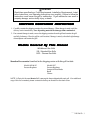
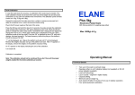
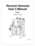
ANETS INC. PO Box 501 Concord, NH 03302-0501 Tel: 603-225-6684, Fax: 603-225-8497 Models MG - Manual Grills SG - Standard Grills SGC - Chrome Grills Installation, User Operation, & Maintenance Manual SGC24X48 on legs shown ! DANGER Improper installation, adjustment, alteration, service, or maintenance can cause property damage, injury or death. Read the installation, operating and maintenance instructions thoroughly before installing or servicing this equipment. ! FOR YOUR SAFETY DO NOT store or use gasoline or other flammable vapors or liquids in the vicinity of this or any other appliance. ! WARNING After installation of this equipment, immediately contact your local gas supplier to obtain information about what action to take whenever any person smells gas. Post this information in a prominent location. Keep this Manual in a Convenient Location for Reference The Anets GoldenLine Quality Equipment For The Restaurant, Supermarket, and Bakery Industries L20-346 Rev 3 CONTENTS Shipping Container Inspection ....................................................... 3 Grill Gas Supply Specifications ...................................................... 4 Code Requirements ...................................................................... 5 Installation Requirements ............................................................... 6 Gas Connection Instructions .......................................................... 6 Grill Operating Instructions ............................................................ 7 Lighting Procedure .................................................................. 7 Grill Preparation For Use .............................................................. 8 Manual & Standard Grill Preparation ....................................... 8 Chrome Grill Preparation ......................................................... 8 Shutdown Procedure .............................................................. 8 Daily Cleaning Procedure ............................................................... 9 Chrome Grill Cleaning Instructions ........................................... 9 Manual & Standard Grill Cleaning Instructions .......................... 9 Monthly Maintenance Instructions .................................................. 9 Grill Troubleshooting Guide ..................................................... 10-12 Grill Warranty .............................................................................. 13 L20-346 Rev3 2 ! DANGER Read these specifications, Code Requirements, Installation Requirements, Installation Instructions, and Operating Instructions very carefully. Failure to follow the Instructions could cause the grill to malfunction. A grill malfunction can result in property damage, serious bodily injury, or death. SHIPPING CONT AINER INSPECTION CONTAINER 1. Carefully examine the shipping container for external damage. When damage is noted, notify the delivery carrier immediately. Save all packing materials for damage claim examination. 2. If no external damage is noted, remove the shipping container from the grill and examine the grill carefully for damage. Place the grill in a safe location, if damage is noted, so that the freight damage claims adjuster can examine the grill. ed By T his Man ual Models Co ver Manual Cov ered MG-Manual Gas Grills SG - Standard Gas Grills SGC - Chrome Gas Grills Standard Accessories furnished in the shipping carton with this grill include: Models MG & SG Pressure Regulator Models SGC Pressure Regulator Scraper & Extra Blades Brush Cleaner NOTE: A Parts List for each Anets Grill is among the items shipped with each grill. If an additional copy of this list is needed, please contact the factory as directed on the back cover. L20-346 RevR3 2 3 L20-346 GRILL GAS SUPPLY SPECIFICATIONS Please make sure that your desired grill location has gas supply factors that are suitable for this product: Natural Gas MANIFOLD PRESSURE* SUPPLY PRESSURE*** 3½“ W.C. ** 6“ W.C., minimum Propane Gas 10“ W.C. 11“ W.C., minimum * - Measured at tap on back side of gas manifold. ** - “ W.C. = Inches, Water Column. *** - Measure supply pressure ahead of pressure regulator when all other gas-powered equipment is operating. Refer to the specification plate on the grill to identify the BTUH input for your specific model. IMPORTANT NOTE: BTU/Hr Ratings are based on sea level operation. For sites above 2000 feet, reduce this rating 4% for each 1000 feet above sea level. Gas Supply Inlet Pipe must be ¾” NPT (National Pipe Thread) standard gas line. The gas supply inlet line should be as straight as possible (fewest bends or elbows) to obtain the highest available gas pressure at the appliance. NOTE: Using a flexible inlet line permits variation in the gas supply line location, both horizontally and vertically. Anets grills are only for use with the type of gas specified on the spec plate. If a grill requires modification to use a gas other than that which is identified on the grill spec plate, contact your Anets representative or call 1-603-225-6684. (800) 837-2638. 4 L20-346 Rev 3 CODE REQUIREMENTS IMPORTANT: Read the Code Requirements and the Installation Requirements and Instructions 1-603-225-6684 carefully, before starting the installation. Contact ANETS (800/ 837-2638) if any problems or questions arise. The grill installation must conform with local codes, or in the absence of local codes, with the National Fuel Gas Code, ANSI Z223.1 (latest edition); the Natural Gas Installation Code, CAN/CGA-B149.1 (latest edition); or the Propane Gas Installation Code, CAN/CGA-B149.2 (latest edition), as applicable, including: (a) Disconnect the grill at its individual shutoff valve from the gas supply piping system during any pressure testing of the gas supply system at test pressures in excess of ½ psig (3.45 kPa). (b) Isolate the grill from the gas supply piping system during any pressure testing of the gas supply system at test pressures equal to or less than ½ psig (3.45 kPa). (c) For grills utilizing the optional stand with casters, the grill installation shall be made with a connector that complies with the Standard for connectors for Movable Gas Appliances,ANSI Z21.69 (latest edition) or CAN/CGA 6.16 (latest edition), and a quick-disconnect device that complies with the Standard for Quick-Disconnect Devices for Use with Gas Fuel, ANSI Z21.41 or CAN/CGA 1-6.9 (latest edition). Restrict the movement of a grill on a caster-equippped stand by using a limiting device (for example, a cable attached both to the grill and to a fixture attached to the site structure) to avoid depending on the connector and the quick-disconnect device or its associated piping to limit grill movement. (d) The regulator supplied with the unit should be installed in the inlet gas supply line with the arrow on the regulator pointing in the direction of the gas flow. (e) Install this grill on a non-combustible cabinet or stand with its back and sides at least 6” away from any combustible wall. ! WARNING Install this grill under a ventilation hood that conducts combustion products outside the building. Venting must comply with ANSI/NFPA 96 (latest edition). (f) Install this grill in a location where adequate combustion and ventilation air is available. Keep the area directly in front of the grill open for adequate air flow to the burners. DO NOT obstruct the flow of combustion and ventilation air. (g) Keep the grill area free and clear from combustibles and debris. L20-346 RevR3 2 5 L20-346 INST ALLA TION REQ UIREMENTS INSTALLA ALLATION REQUIREMENTS Install the grill in accordance with the preceding Code Requirements, as well as the following Installation Requirements. 1. DO NOT install this grill in a mobile home, trailer, or recreational vehicle. 2. Install this grill in a location that allows it to be moved away from other adjacent appliances for cleaning and maintenance. NOTE: If the grill is installed among a row of appliances, with its only convenient movement forward, sufficient room must be available in front of the grill to permit its separation from adjacent appliances for cleaning and maintenance. ! CAUTION: Hood make-up air MUST NOT flow in a manner that restricts or impedes the natural flow of combustion or ventilation air. 3. Confirm that the air from the ventilation hood flowing near the grill after installation is NOT blowing on the rear of the unit, to prevent affecting the burner flames and possibly causing damage to plastic parts. GAS CONNECTION INSTRUCTIONS Installing your ANETS Grill requires the following procedure: 1. Ensure that all the gas control valve knobs on the grill are turned to the “OFF” position. 2. Ensure that the gas supply inlet line valve is closed (handle crosswise to the line direction). 3. Connect the ¾” gas supply line to the gas line regulator in the rear of the grill. ! WARNING DO NOT use a flame to check for leaks. 4. Open the gas supply line valve (handle in-line with line direction); then, confirm that all gas supply joints and couplings are free of leaks using soap suds or a leak-check solution, after the grill is in its desired location. 5. Refer to Grill Operating Instructions to begin using your ANETS Grill. 6 L20-346 Rev 2 R3 GRILL OPERA TING INSTR UCTIONS OPERATING INSTRUCTIONS CAUTION DO NOT operate this grill during an interruption of gas service. Turn all grill controls to OFF, including the gas control valve knobs, then close the gas supply line valve. When notified that the gas service has resumed, perform the Lighting Procedure descibed below. ! DANGER NEVER operate this grill when its flue is blocked or when the ventilation hood is not on because the combustion products can accumulate and cause serious injury or death. ! DANGER Avoid moving the grill while it remains HOT. Let the grill cool before moving it for service, cleaning, or maintenance to avoid burns. A. Schedule regular cleanings of the grill to ensure long-term satisfactory operation. Refer to the Daily Cleaning Procedure, later in this manual. B. Before servicing and maintenance, allow the grill to cool. ALWAYS shut off gas to the grill while working on it, to prevent personal injury. C. Contact the factory (800-837-2638) 1-603-225-6684 for warranty service authorization. [Always notify the factory the next business day about ‘after-hours’ warranty service.] Contact your local restaurant equipment service agency for other service, repairs, or maintenance activities, as necessary. LIGHTING PROCEDURE 1. Push in and turn gas control know to “OFF”. Wait 5 minutes for any possible accumulation of gas in combustion area to escape. 2. Turn the gas control know to “PILOT”. Push the knob in and depress the spark ignitor several times to ignite the pilot. 3. Continue to hold the knob in for 30 seconds. If the pilot goes out when the knob is released, repeat steps 1, 2, and 3. 4. Repeat this procedure for all the pilots present. 5. Turn the safety shutoff to “ON” and then set the thermostat (or manual burner valve if so equipped). L20-346 Rev R3 2 7 L20-346 GRILL PREP ARA TION FOR USE PREPARA ARATION MANUAL AND STANDARD GRILLS ONLY (DO NOT USE FOR CHROME GRILL) Conditioning Instructions - MG & SG Models ONLY 1. Upon examination of your grill you will notice that the grill plate is covered with a protective grease. To remove this grease, turn grill thermostats to about 250°F setting (or low setting on manually operated grills). As the grill plate warms up, carefully wipe the rust preventative grease off of the grill plate and side and rear splash plates with a soft cloth. 2. When cleaning has been completed, apply a film of cooking oil to the grill plate with a small amount of salt. Allow plate to season for about 1 hour at 250°F while rubbing oil and salt into the grill surface. Add oil and salt as required on any “dry spots” that appear during this seasoning process. 3. After 1 hour at 250°F, advance the thermostat setting to 300°F. Continue use of salt and oil for about 1 hour at 300°F. At the end of 1 hour at 300°F, a light tan uniform coating should be present on the top surface of the grill plate. If it has not developed, continue seasoning process as above at 350°F until coating is formed. Note: On manually operated grills, keep the grill on low setting during entire seasoning process. Following initial “Conditioning” of the grill plate, the thermostats may be set to the desired temperature. CHROME GRILL Conditioning Instructions - SGC Models ONLY 1. Spread a coating of cooking oil evenly over the surface of the grill. Set the thermostats to 350°F and allow to heat for 1 hour. 2. Using the scraper provided, remove any carbonized material before cooking. GRILL SHUT DOWN PROCEDURE 1. To turn the grill off, turn the gas control valve to the “Pilot” position. To extinguish the pilot burners, turn to the “Off” position. 2. If burner flames are accidentally extinguished or the safety shutoff valves closes due to pilot failure, turn all valves off. Allow the unit to vent for at least 5 minutes before attempting to re-light. 8 L20-346 Rev 3 DAIL Y CLEANING PR OCEDURE AILY PROCEDURE Standard Grill Cleaning Instruction (MG & SG Models Only) 1. Clean grill plate often to prevent sticking and poor quality of product. 2. Scrape the grill plate regularly with a spatula or scraper to remove all surface grease and food particles. 3. For thorough cleaning, use a grill brick or grill screen to remove carbon build up on grill plate. Do not use any abrasive or caustic cleaners or pads on the exterior surface of the unit. Use only cleaners and polishes recommended for stainless steel. Note: It may be necessary to season grill again after this cleaning. 4. To clean grease drawer, slowly and carefully remove from cabinet. Cautiously pour contents into container, wash out grease drawer. Wipe dry and reinstall into grill cabinet. Chrome Grill Cleaning Instructions (SGC Models) IMPORTANT: Do not use any abrasive or caustic cleaners or pads on chrome grills. SIMPLE 3 STEP PROCESS….. Scrape, Scrub, Shine 1. Scrape – with the razor scraper provided. Make sure razor edge is exposed. (The blade is turned inward during shipping for safety protection.) 2. Scrub - with the palmyra cleaning brush provided and cool water. 3. Shine - (only if necessary) with Bon Ami™ cleanser, water, and a soft cloth. Note: It may be necessary to condition grill again after this cleaning. 4. To clean grease drawer, slowly and carefully remove from cabinet. Cautiously pour contents into container, wash out grease drawer. Wipe dry and reinstall into grill cabinet. DO NOT use a grill brick or grill screen or any caustic cleansers as this will damage the chrome surface. MONTHL Y MAINTEN ANCE INSTR UCTIONS MONTHLY MAINTENANCE INSTRUCTIONS NOTE: Regular maintenance is strongly recommended to keep the grill operating properly. Once each month, before beginning grill operation, check the flue (behind the backsplash panel) to ensure that it is clear and free of obstructions, enabling exhaust combustion gases to flow freely toward the ventilation hood area. DO NOT allow the flue to become excessively dirty, NEVER allow the flue to be blocked. Monthly, observe the condition of the ventilation hood. If it shows evidence of a great deal of greasy residue, remove (clean) the residue to allow free flow of ventilation air, taking care not to knock any residue into grill flue. L20-346 Rev3 9 GRILL TR OUBLESHOO TING GUIDE TROUBLESHOO OUBLESHOOTING All service (repairs or part replacement) must be performed by a qualified Service Agency. PROBLEM TEST Pilot (piezo-electric) 1. Check if igniter is generating a spark. pushbutton igniter does not light the pilot flame. 2. Check for loose spark wire or igniter nut. Pilot flame does not stay lit. L20-346 Rev3 1. Yes - Skip to test #3. No - Proceed with test #2. 2. Yes - Tighten, skip to #5 No - Proceed with test #3 3. Check position of electrode 3/16” from pilot burner tip. 3. Yes - Skip to test #4. No - Reposition electrode and skip to test #5 4. Check for dirty/sooty electrode. 4. Yes - Clean, skip to test #5 No - Proceed with test #5 5. Retry igniter. 5. Lights - Okay. Doesn’t light - Replace igniter mechanism. 1. Observe if pilot flame is “wavering” (being blown about by a draft). 1. Yes - Block or redirect the draft to keep the flame burning steadily. Skip to test #6. No - Proceed with test #2. 2. Observe if pilot flame is too small to heat thermocouple. 2. Yes - Adjust the pilot valve (part of gas control valve) to increase the flame size, un screw and retain the slotted threaded cover; turn the pilot valve adjustment screw two turns counter clockwise; reinstall the threaded cover. Skip to test #6. No - Proceed with test #3. 3. Check for dirty/sooty pilot burner. 3. Yes - Clean. Skip to test #6. No - Proceed with test #4 . 4. Check thermocouple output voltage. 4. More than 10 millivolts proceed with test #5. Less than 10 millivolts replace thermocouple, skip to test #6. 5. Check gas supply pressure with all other equipment operating. (6” WC for natural gas and 11” WC for propane, minimum) 5. Increase if needed, proceed with test #6. 6. Observe pilot flame. 10 REMEDY 6. Stays lit - Okay. Does not stay lit - Replace gas control valve. GRILL TR OUBLESHOO TING GUIDE TROUBLESHOO OUBLESHOOTING PROBLEM Main burners do not ignite. CAUSE (Continued) REMEDY 1. Check that gas control valve is set to “ON”. 1. Yes - Proceed to test #2. No - Turn to “ON” and skip to test #5. 2. Check that pilots are burning. 2. Yes - Proceed to test #3 No - Follow lighting instructions on page 7. Skip to test #5. 3. Increase temperature setting on thermostat control. 3. Proceed to test #4. 4. Check gas supply pressure with all other equipment operating. (6” WC for natural gas and 11” WC for propane, minimum) 4. Increase if needed, proceed to test #5. 5. Yes - Okay. No - Replace gas control valve. 5. Observe if main burners ignite. Over temperature or main burners do not stop burning. 1. Turn thermostat control to “OFF”. Observe if main burners go off. 1. Yes - Skip to test #3. No - Proceed with test #2. 2. Turn gas control valve knob to “OFF”. Observe if main burners go off. 2. Yes - Proceed with test #3. No - Replace gas control valve. 3. Reset thermostat control to desired setting. Observe if main burners go off when temperature is reached. Grill plate is cold (Burners not firing). 3. Yes - Okay. No - Replace thermostat. 1. Check that gas supply is turned on. 1. Yes – Proceed to test #2. No – Turn on, follow Lighting Instructions on page 7. Skip to test #4. 2. Check for lit pilot. 2. Yes – Proceed to test #3 No – Follow Lighting Instructions on page 7. Skip to test #6. 3. Check that gas control valve is in “ON” position. 3. Yes – Proceed to test #4. No – Turn to “ON”. Skip to test #6. 4. Check that thermostat control is at desired setting. 4. Yes – Proceed to test #5. No – Increase setting. Proceed to test #5. L20-346 Rev3 11 GRILL TR OUBLESHOO TING GUIDE TROUBLESHOO OUBLESHOOTING PROBLEM (Continued) Grill plate is cold (Burners not firing). CAUSE 5. Check gas supply pressure with all other equipment operating. (6” WC for natural gas and 11” WC for propane, minimum). (Continued) REMEDY 5. Increase if needed, proceed to test #6. 6. Yes - Okay. No - Replace thermostat. 6. Observe if main burners are firing. Grill plate is not hot enough. Black soot accumulation on burners on under side of grill plate. 1. Check that thermostat control setting is at desired setting. 1. Yes – Proceed to test #2. No – Increase setting. Skip to test #5. 2. Check gas supply pressure with all other equipment operating. (6” WC for natural gas and 11” WC for propane, minimum). 2. Above – Proceed to test #3. Below – Increase gas supply pressure. Skip to test #5. 3. Check for fans or excessive air flow over grill surface. 3. Yes – Block or turn off air supply. Skip to test #5. No –P proceed to test #4. 4. Check for dirty/sooty pilot burner. 4. Yes – Clean pilot burner. Proceed to test #5. No – proceed to test #5. 5. Observe if grill plate temperature is acceptable. 5. Yes – Okay. No – Replace thermostat. 1. Check if pressure regulator is installed in supply line. 1. Yes – Proceed to test #2 No – Install regulator supplied with unit. Proceed to test #2. 2. Adjust pressure regulator setting by turning the adjusting slot counterclockwise (under the slotted cap). 12 L20-346 Rev3 ORIGINAL EQUIPMENT LIMITED WARRANTY General Warranty Anets, Inc. warrants to the original user of its commercial cooking appliances and related equipment that said appliances and related equipment will be free from defects in material and workmanship under normal use for a period of one (1) year from the date of installation, with appropriate documentation, to a maximum of fifteen (15) months from the date of manufacture, subject to the following additions, exceptions, exclusions and limitations. What is covered This warranty is limited to the repair or replacement at the Company’s option, without charge, of any part found to be defective within the warranty period and reasonable expenses incurred for freight and material for the installation of such part; in addition, the Company’s obligation shall be limited to reimbursement for normal labor on such parts. Anets, Inc. agrees to pay the Authorized Service and Parts Distributor, for any labor and material required to repair or replace, at the Company’s option, any part which may fail due to defects in material or workmanship during the above general warranty period. Silver Line Fryers In addition to the above general warranty, for its economy fryers and cookers, the Company warrants to the original user any mild. Stainless steel fry tank or cooking vessel to be free from defects for a period of one (1) year, from the date of manufacture. Labor and freight shall be the responsibility of the end user. Gold Line Fryers In addition to the above general warranty, for its standard fryers and cookers, the Company warrants to the original user any stainless steel fry tank or cooking vessel to be free from defects for a period of (1) year parts and labor and 10 year Frypot or cooking vessel Part only from the date of manufacture Labor and freight shall be the responsibility of the end user. Pasta Cooker In addition to the above general warranty, for its standard fryers and cookers, the Company warrants to the original user any stainless steel fry tank or cooking vessel to be free from defects for a period of one (1) year parts and labor and 5 years Frypot or cooking vessel part only after year one from the date of manufacture. Labor and freight shall be the responsibility of the end user. Limitations to Fry Tank and Cooking Vessel Warranty After the expiration of the general warranty period, any additional warranty on fry tanks or cooking vessels shall only obligate the Company to repair or replace, at its option, any fry tank or cooking vessel which it determines to be defective. Claims under this item shall be supported by a statement detailing the defect, and the Company may require the return of the fry tank or cooking vessel claimed to be defective. Labor and freight shall be the responsibility of the end user. How to Keep Your Warranty in Force • Make sure any shipping damages are reported immediately. Damages of this nature are the responsibility of the carrier and must be reported by the receiver. • Install the unit properly. This is the responsibility of the installer and the procedures are outlined in the manual. • Do not install it in a home or residence. • Maintain it properly. This is the responsibility of the user of the appliance and the procedures are outlined in the manual. • Adjustments, such as calibration, leveling, tightening of fasteners or plumbing or electrical connections normally associated with initial installation. These procedures are outlined in the manual and are NOT covered by warranty. • If it is damaged due to flood, fire or other acts of God, this is not covered under this warranty. •Use it for what it is intended. If it is used for a purpose other than for which it was intended or designed, resulting damages are not covered under the warranty. • Make sure that it has the correct voltage, gas supply and/or good quality water. If a failure is due to poor water quality, harsh chemical action, erratic voltage or gas supplies, these damages are not covered under the warranty. • Do not materially alter or modify from the condition in which it left the factory. • Do not obliterate, remove or alter the serial number rating plate. • Use only Genuine OEM parts from Anets, Inc. or its Authorized Parts and Service Distributors. Repairs are not covered by the warranty. • If any other failure occurs which is not attributable to a defect in materials or workmanship, it is not covered. This warranty specifically excludes parts which wear or would be replaced under normal usage, including, but not limited to, electric lamps, fuses, interior or exterior finishes, o-rings and gaskets. Limits to the Warranty Outside the United States of America and Canada, this warranty is limited to the replacement of parts and Anets, Inc. will not bear any other expense be it labor, mileage, freight or travel. If any oral statements have been made regarding the appliance, these statements do not constitute warranties and are not part of the contract of sale. This limited warranty constitutes the complete, final and exclusive statement with regard to warranties. THIS LIMITED WARRANTY IS EXCLUSIVE AND IS IN LIEU OF ALL OTHER WARRANTIES WHETHER WRITTEN, ORAL OR IMPLIED, INCLUDING, BUT NOT LIMITED TO ANY WARRANTY OF MERCHANTABILITY OR FITNESS FOR A PARTICULAR PURPOSE OR WARRANTY AGAINST LATENT DEFECTS. Limitations of Liability In the event of a warranty or other claim, the sole obligation of Anets, Inc. will be the repair or replacement, at the Company’s option, of the appliance or the component part. This repair or replacement will be at the expense of Anets, Inc. except as limited by this warranty statement. Any repair or replacement under this warranty does not constitute an extension in time to the original warranty. Parts covered under this warranty will be repaired or replaced, at the Company’s option, with new or functionally operative parts. The liability of Anets, Inc. on any claim of any kind, including claims based on warranty, express or implied contract, negligence, strict liability or any other legal theories will be exclusively the repair or replacement of the appliance. This liability will not include, and the purchaser specifically renounces any right to recover special, incidental, consequential or other damages of any kind, including, but not limited to, injuries to persons, damage to property, loss of profits or anticipated loss of the use of this appliance. If any provision of this warranty is unenforceable under the law of any jurisdiction, that provision only will be inapplicable there, and the remainder of the warranty will remain unaffected. The maximum exclusion or limitation allowed by law will be substituted for the unenforceable provision. How to Obtain Warranty Service First direct your claim to the Anets, Inc. Authorized Service and Parts Distributor closest to you giving complete model, serial and code numbers, voltage, gas type, and description of the problem. Proof of the date of installation and/or the sales slip may also be required. If this procedure fails to be satisfactory, write the National Service Manager, Anets, Inc., P. O. Box 501, Concord, NH. 03302-0501. USA This warranty gives you certain specific legal rights; you may have other rights which vary from state to state. Anets,Inc.,ǤǤͷͲͳǡ ǤǦͺͻƬǦͻ͵ ǡͲ͵͵ͲʹǦͲͷͲͳ ͷͲͻ͵ǡǡͲ͵͵ͲͶ ǣȋͲ͵ȌʹʹͷǦͺͶǣȋͲ͵ȌʹʹͺǦͷʹ͵ͳwww.ANETS.com L14022R1PrintedinU.S.A. In the event of problems with or questions about your order, please contact the Anets factory at: (603)-225-6684 World Wide Website Address: www.anets.com In the event of problems with or questions about your equipment, please contact the Anets Authorized Service and Parts representative (ASAP) covering your area, or contact Anets at the number listed to the left. MAILING ADDRESS – P.O. BOX 501, CONCORD, NH 03302-0501 SHIPPING ADDRESS – 10 FERRY STREET, CONCORD, NH 03301 L20-346 Rev3